Design of DSP with an Optimized Multiplier
Using Approximate Compressor
Maria Sunny, Haripriya P
PG Student, Department of ECE, Sree Narayana Gurukulam College of Engineering, Kadayiruppu, Kerala, India
Assistant Professor, Department of ECE, Sree Narayana Gurukulam College of Engineering, Kadayiruppu, Kerala,
India
ABSTRACT: Approximate computing is an emerging trend for digital processing computation at nanoscale. Inexact computation is particularly used in applications such as multimedia, image processing that can tolerate errors and yet produce meaningful results. In this paper, an inexact 16-bit multiplier is implemented using approximate compressor. Efficient implementation of such a multiplier, along with an area efficient carry select adder is used in a custom digital signal processor. Experimental results show that the proposed design accomplishes significant reduction in power dissipation, area and delay indicating its use in the VLSI applications.
KEYWORDS: Compressor; Approximate Multiplier; Programmable Truncated Multiplier; Carry Select Adder; Custom DSP.
I. INTRODUCTION
Methodologies for approximate (or inexact) computing rely on the fact that many applications like multimedia, image processing, can tolerate some errors and imprecision in computation and, therefore, the solution can tolerate some degree of uncertainty. Commonly used multimedia applications have Digital Signal Processing (DSP) blocks as their backbone. Multiplication is commonly required in digital signal processing and act as one of the fundamental building block.
Most of these DSP blocks implement image and video processing algorithms, where the final output is either an image or a video for the consumption by humans. The limited perception of human vision allows the outputs of these algorithms to be numerically approximate (inaccurate) rather than accurate. This relaxation on numerical exactness allows us to carry out approximate computation. Deterministic, exact and precise models are not always suitable to be applied on these situations.
Parallel multipliers give high speed method for multiplications, but require large area for VLSI implementation. The increase in use of portable communication, computing devices and advancement in mobile multimedia applications has made power consumption and area critical to optimize in the design of digital signal processing architectures.
Full or direct multiplier implementations of an N X N bit multiplication gives a 2N -bit product. In order to keep the full accuracy, DSP architecture would need an ever-growing bit width that would be impractical to implement. To avoid this, results are usually truncated to keep results within the limits of the architecture bit width.
While many specific applications require the bit width of inputs and the outputs of the multiplier to be the same, general purpose digital signal processors need flexibility to support the generation of large output results in accumulators where the magnitude of the output is bigger than the multiplier inputs. Programmable truncated multipliers are multipliers where parts of the partial product matrix can be disabled at run-time by introducing a truncation bit in the matrix [1]. Though the power is reduced, area increases as the 2-input and-gate is replaced by 3-input and-gate. In the design of a fast multiplier, compressors have been extensively used to speed up the partial product reduction tree and decrease power dissipation. Multipliers based on approximate compressors have been used.
II. RELATED WORK
A. Programmable Truncated Multiplier:
Truncation exhibits a way of reducing the complexity of the multiplier unit by discarding the lower parts of the partial product matrix. Thus errors are mostly being generated in the lower weighted bits of the output and they are discarded while converting the output back to the original bit width. By doing so, significant reduction in power and complexity can be achieved, but at the expense of signal degradation.
Programmable truncated multipliers are multipliers where parts of the partial product matrix can be disabled at run-time by introducing a truncation bit, i.e., by reducing or eliminating switching activity. Taking as a starting point a full 2N–bit multiplier, where the full partial product matrix is computed in order to produce an exact two‟s complement
result, this architecture provides a method to adjust the active width of the multiplier following a column-based strategy, thus allowing a flexible truncation scheme capable of adapting the power consumption to the requirements of the application.
Fig.1. Partial Product Matrix For an 8-bit Programmable Truncated Multiplier
The column-wise controllability of the active state of the partial product terms is achieved by replacing the 2-input AND gates that form the original partial product terms by 3-input AND gates, assigning one of the inputs to the corresponding truncation bit. Since 3-input AND gates require an area overhead of 20% of 2-input ones, adding programmable truncation results in a maximum area penalty of 20% to the partial product matrix.
The multiplier input „t‟ controls the functionality of the programmable partial product units that generate the final output. Each of the bits within is connected to the extra input bit of the 3-input AND gates that form the corresponding column in the partial product matrix. If „t=0x7FFF‟ in Fig. 1, all partial products are generated without truncation, and the result will be equal to that obtained by a full-precision multiplier. A value of „t=0x7000‟ will result in half the
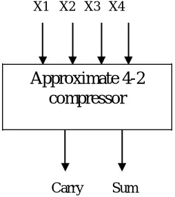
B. Approximate Compressor:
X1 X2 X3 X4
Approximate 4-2
compressor
Carry Sum
Fig.2. Approximate Compressor, Design 2
Originally there are two designs proposed for approximate compressors [2]. In this paper, we concentrate on design 2. In [2], the carry and cout outputs have the same weight and cout is always equal to cin while comparing the truth table of exact compressor and design1. Again, since cin is zero in the first stage, cout and cin will be zero in all stages. Therefore, cin and coutof exact compressor can be ignored in the hardware design as shown in Fig 2.So the equation for
the approximate compressor, design 2 will be as follows:
′ = x1 x2 + x 3 x 4 (1)
+
′ = (x1x2 x3x4) (2)
Fig.3 shows the gate level implementation of design 2. Design 2 becomes the addition of four inputs as cin and cout
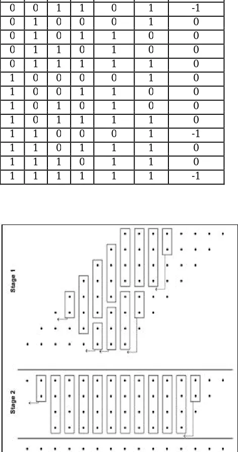
are ignored from the design. Table I shows the truth table of second approximate design of 4-2 compressor. It presents the difference between the exact values of the addition of inputs and that produced by the approximate compressor.
Table I: Design 2, Approximate Compressor
X4 X3 X2 X1 Carry’ Sum’ Difference
0 0 0 0 0 1 1
0 0 0 1 0 1 0
0 0 1 0 0 1 0
0 0 1 1 0 1 -1
0 1 0 0 0 1 0
0 1 0 1 1 0 0
0 1 1 0 1 0 0
0 1 1 1 1 1 0
1 0 0 0 0 1 0
1 0 0 1 1 0 0
1 0 1 0 1 0 0
1 0 1 1 1 1 0
1 1 0 0 0 1 -1
1 1 0 1 1 1 0
1 1 1 0 1 1 0
1 1 1 1 1 1 -1
C. Approximate Multiplier:
An exact multiplier is usually comprised of three parts:
• Partial product generation.
• A Carry Save Adder (CSA)
• A Carry Propagation Adder (CPA)
The first part is the generation of partial product matrix. The second part is a Carry Save Adder (CSA) tree to reduce the partial products‟ matrix to an addition of only two operands. The third part comprises of a Carry Propagation Adder (CPA) for the final computation of the binary result.
In the design of a multiplier, the second module, ie, the carry save adder, plays a pivotal role in terms of delay, power consumption and circuit complexity. Compressors have been widely used to speed up the CSA tree and decrease its power dissipation, so as to achieve faster and low-power operation. Approximate compressors when used in the CSA tree of a multiplier, we get an approximate multiplier.
An 8×8 unsigned Dadda tree multiplier is used to assess the impact of using the approximate compressors in the multiplier. The multiplier uses in the first part AND gates to generate all partial products. In the second part, the approximate compressors of design 2are used in the CSA tree to reduce the partial products. The last part is an exact CPA to compute the final binary output.
Fig.4 shows the reduction circuitry of an exact multiplier for n=8. In this figure, the reduction part uses half-adders, full-adders and 4-2 compressors where each partial product bit is represented by a dot. Since Design 2 does not have
cin and cout, the reduction circuitry of this multiplier requires a lower number of compressors (Fig.4). Multiplier uses 6 half-adders, 1 full-adder and 17 compressors. It has better performance in terms of delay and power consumption.
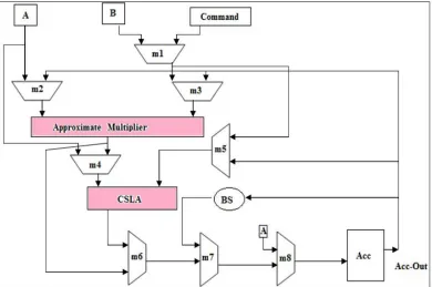
III. PROPOSED DSP ARCHITECTURE
The design 2 approximate multiplier is implemented into a DSP. The architecture presented in this paper is a custom-designed DSP structure with minimum control logic and core importance is given to arithmetic unit designed with an accumulator, barrel shifter, approximate multiplier and an area efficient carry select adder. Fig.5 shows the DSP architecture used in this paper. The main characteristics of the architecture are described as follows:
1) Control Unit: The Control Unit is a small 5 -stage pipeline that fetches and decodes instructions, and controls the data flow, arithmetic unit and the I/O ports. Its design has been reduced to a structure as simple as possible with the objective of minimizing the power spent by any non-arithmetic operations. It allows the user to access one or both of the data memory blocks while reading instructions. Circular buffers are included for efficient access of both memory blocks, again to maximize the use of the Arithmetic Unit. DSP includes four general purpose registers within its Control unit.
2) Custom Instruction Set: The set of instructions implemented has been designed to maximize the usage of the Arithmetic Unit, optimizing the power reductions achievable by the multiplier. Instructions are 32 bits wide and allow access to one or both memory blocks in a single instruction. The instruction set is split into different functional areas, as explained below:
a)Arithmetic Instructions: The Arithmetic instructions are displayed in Table II. It is focused on the arithmetic capabilities of the unit. The range of instructions dedicated to arithmetic operations includes ADD for addition, MULT for multiplication and MAC for multiply-and-accumulate operations. Variations of such instructions include instructions that enable operations with memory data or registers, and accumulators squaring are also included along with a single instruction to control the scaling/shifting of the accumulator via the barrel shifter. All instructions that perform operations on data from the memory blocks post-increment the value of the affected data memory pointers automatically.
c) Looping Instructions: Looping instructions have been implemented aimed at a reduction in flow-control instructions, maximizing the duty of the arithmetic unit. Instructions allow set up and use of circular buffering in both data memory blocks and hardware defined loops for efficient code execution. It is also possible to repeatedly execute a single instruction without the need of reloading it from memory.
d)Data Flow Instructions: Data Flow instructions make reference to instructions for storing and loading data and also inputting and outputting samples to/from the system. Data can be stored and loaded in the different memory blocks, the accumulator or in one of the general use registers by selecting the appropriate instruction.
3)Memory blocks: Memory on the PTMAC architecture is formed by a 1024, 32 bit Program Memory block and two 512, 16 bit Data Memory blocks. All three memories can be accessed on a single clock cycle, as they are directly connected to the control unit.
Fig.5. DSP Architecture
4) Arithmetic Unit: The Arithmetic Unit is the core unit of this DSP. It consists of a multiply and accumulate structure with main units as:
a 16-bit approximate multiplier,
a 40-bit area efficient carry select adder [3], an accumulator and ,
Fig.6. Arithmetic Unit Diagram Table II: Arithmetic instructions
Mnemonics Commands(Hex)
ADD 10xxxxxx
ADD_RD,A,B 13xABBBB
MULT 20xxxxxx
MAC 30xxxxxx
MAC_ RD,A,B 33xABBBB
SQ_ACC,A 32xxxxxA
SHIFT_ACC 90xxABCC
Other instructions like looping, flow control,dataflow along with its mnemonic,command and description aregiven in[1].
IV. RESULTS & DISCUSSION
DSP is implemented in Xilinx 13.3 using Verilog programming language. A 16x16 approximate multiplier is implemented and a comparison is made with programmable truncated multiplier. Performance comparison in terms area, and delay are shown in Table III.
DSP with programmable truncated multiplier (PTM) uses ripple carry adder as the adder unit while DSP with approximate multiplier uses area efficient carry select adder. Arithmetic units of these DSP‟s are being compared.
of area indicates that DSP using approximate compressors can be used for various applications like image processing, multimedia etc.
Table III: Performance Comparison of Multipliers
Metrics compared Programmable Approximate
Truncated Multiplier
Multiplier(PTM) (AM)
No. of Slices
(4656) 414
292
No .of 4 i/p LUT’s
(9312) 720 509
Delay (ns) 40.596
35.512
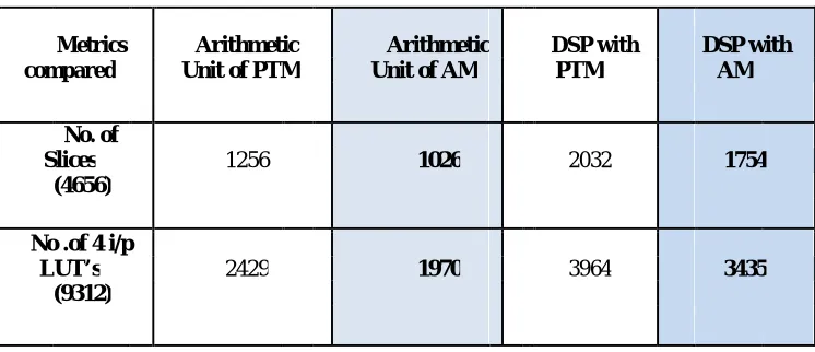
Table IV: Performance Comparison of Arithmetic Units & DSP‟s
Metrics
Arithmetic
Arithmetic
DSP with
DSP with compared Unit of PTM Unit of AM PTM AM
No. of
Slices 1256 1026 2032 1754
(4656)
No .of 4 i/p
LUT’s 2429 1970 3964 3435
(9312)
V. CONCLUSION AND FUTURE WORK
REFERENCES
1. Manuel de la Guia Solaz,Wei Han, and Richard Conway, “A Flexible Low Power DSP With A Programmable Truncated Multiplier,” IEEE Transaction on Circuits and Systems, Vol 59, n0.11.
2. A.Momeni,J.Han Member, P.Montuschi, and F. Lombardi, Fellow, “ Design and Analysis of Approximate Compressors for Multiplication ” IEEE Trans. Computer., vol. 56, no. 4, pp, Apr. 2013.
3. B Ramkumar and Harish M Kittur. “ Low Power and Area Efficient Carry Select Adder”, IEEE Transaction on VLSI, Vol 20, no 2. 4. Michael .J. Schulte and E .George Walters, “Design Alternatives Of Barrel Shifter”, IEEE journal on Circuits and Systems.
5. M. J. Schulte and E. E. Swartzlander, Jr., “Truncated multiplication with correction constant,” VLSI Signal Processing VI, pp. 388–396, 1993 6. S. Cheemalavagu, P. Korkmaz, K.V. Palem, B.E.S. Akgul, and L.N. Chakrapani, “A probabilistic CMOS switch and its realization by exploiting
noise,” in Proc. IFIP-VLSI SoC, Perth, Western Australia, Oct. 2005.
7. E. J. King and E. E. Swartzlander, Jr., “Data dependent truncated scheme for parallel multiplication,” in Proceedings of the Thirty First Asilomar Conference on Signals, Circuits and Systems, pp. 1178–1182, 1998.
8. J. Gu, C. H. Chang, “Ultra Low-voltage, low-power 4-2 compressor for high speed multiplications,” in Proc. 36th IEEE Int. Symp. Circuits Systems, Bangkok, Thailand, May 2003.
9. P. Kulkarni, P. Gupta, and MD Ercegovac, “Trading accuracy for power in a multiplier architecture”, Journal of Low Power Electronics, vol. 7, no. 4, pp. 490--501, 2011.
10.C. Chang, J. Gu, M. Zhang, “Ultra Low-Voltage Low- Power CMOS 4-2 and 5-2 Compressors for Fast Arithmetic Circuits,” IEEE Transactions on Circuits & Systems, Vol. 51, No. 10, pp. 1985-1997, Oct. 2004.
11. D. Radhakrishnan and A. P. Preethy, “Low-power CMOS pass logic 4-2 compressor for high-speed multiplication,” in Proc. 43rd IEEE Midwest Symp. Circuits Syst., vol. 3, 2000, pp. 1296–1298.
12. S. Kidambi, F. El-Guibaly, and A. Antoniou, “Area-efficient multipliers for digital signal processing applications,” IEEE Trans. Circuits Syst.II, Analog Digit. Signal Process., vol. 43, no. 2, pp. 90–95, Feb.1996.
BIOGRAPHY