Design of Area Efficient FIR Filter Architecture for Fixed and
Reconfigurable Applications
Sayabugari Nithisha
&
Ch.Gnaneshwar
1PG Scholar, Vlsi, Dvr College Of Engineering And Technology, Kashipur
Kandi, Sangareddy, Telangana.
2assistant Professor, Department Of Ece, Dvr College Of Engineering And Technology, Kashipur, Kandi,
Sangareddy, Telangana.
Abstract:
In this paper, we explore the possibility of realization of block FIR filter in transpose form configuration for area-delay efficient realization of large order FIR filters for both fixed and reconfigurable applications. A generalized block formulation is presented for transpose form FIR filter. Transpose form finite-impulse response (FIR) filters are inherently pipelined and support multiple constant multiplications (MCM) technique that results in significant saving of computation. We have derived a general multiplier-based architecture for the proposed transpose form block filter for reconfigurable applications. A low-complexity design using the MCM scheme is also presented for the block implementation of fixed FIR filters. The proposed structure involves significantly less area delay product (ADP) and less energy per sample (EPS) than the existing block implementation of direct-form structure for medium or large filter lengths, while for the short-length filters, the block implementation of direct-form FIR structure has less ADP and less EPS than the proposed structure. Synthesis and Simulation is done by using Xilinx ISE Design Suite.Index Terms— Block processing, finite-impulse response (FIR) filter, reconfigurable architecture, VLSI.
I. INTRODUCTION
FINITE-impulse response (FIR) filters play a crucial role in many signal processing applications in communication systems. A wide variety of tasks such as spectral shaping, matched filtering, interference cancellation, channel equalization, etc. can be performed with these filters. Hence, various
architectures and implementation methods have been proposed to improve the performance of filters in terms of speed and complexity. Recently, with the advent of software defined radio (SDR) technology, finite impulse response (FIR) filter research has been focused on reconfigurable realizations. The fundamental idea of an SDR is to replace most of the analog signal processing in the transceivers with digital signal processing in order to provide the advantage of flexibility through reconfiguration. This will enable different air-interfaces to be implemented on a single generic hardware platform to support multistandard wireless communications. The most computationally intensive part of an SDR receiver is the channelizer since it operates at the highest sampling rate.
Several designs have been suggested by various researchers for efficient realization of FIR filters (having fixed coefficients) using distributed arithmetic (DA) [18] and multiple constant multiplication (MCM) methods [7], [11]–[13]. DA-based designs use lookup tables (LUTs) to store pre-computed results to reduce the computational complexity. The MCM method on the other hand reduces the number of additions required for the realization of multiplications by common subexpression sharing, when a given input is multiplied with a set of constants. The MCM scheme is more effective, when a common operand is multiplied with more number of constants. Therefore, the MCM scheme is suitable for the implementation of large order FIR filters with fixed coefficients. But, MCM blocks can be formed only in the transpose form configuration of FIR filters.
only provides throughput-scalable design but also improves the area-delay efficiency. The derivation of block-based FIR structure is straightforward when direct-form configuration is used [16], whereas the transpose form configuration does not directly support block processing. But, to take the computational advantage of the MCM, FIR filter is required to be realized by transpose form configuration. Apart from that, transpose form structures are inherently pipelined and supposed to offer higher operating frequency to support higher sampling rate.
Several designs have been suggested during the last decade for efficient realization of reconfigurable FIR (RFIR) using general multipliers and constant multiplication schemes [7]–[10]. But, we do not find any specific block-based design for RFIR filter in the literature. A block-based RFIR structure can easily be derived using the scheme proposed in [15] and [16]. But, we find that the block structure obtained from [15] and [16] is not efficient for large filter lengths and variable filter coefficients, such as SDR channelizer. Therefore, the design methods proposed in [15] and [16] are more suitable for 2-D FIR filters and block least mean square adaptive filters.
In this paper, we explore the possibility of realization of block FIR filter in transpose form configuration in order to take advantage of the MCM schemes and the inherent pipelining for area-delay efficient realization of large order FIR filters for both fixed and reconfigurable applications. The main contributions of this paper are as follows.
1) Computational analysis of transpose form configuration of FIR filter and derivation of flow graph for transpose form block FIR filter with reduced register complexity.
2) Block formulation for transpose form FIR filter.
3) Design of transpose form block filter for reconfigurable applications.
4) A low-complexity design method using MCM scheme for the block implementation of fixed FIR filters.
II. COMPUTATIONAL ANALYSIS AND MATHEMATICAL FORMULATION OF
BLOCK TRANSPOSE FORM FIR FILTER The output of an FIR filter of length N can be computed using the relation
The computation of (1) can be expressed by the recurrence relation
A. Computational Analysis The data-flow graphs (DFG-1 and DFG-2) of transpose form FIR filter for filter length N = 6, as shown in Fig. 1, for
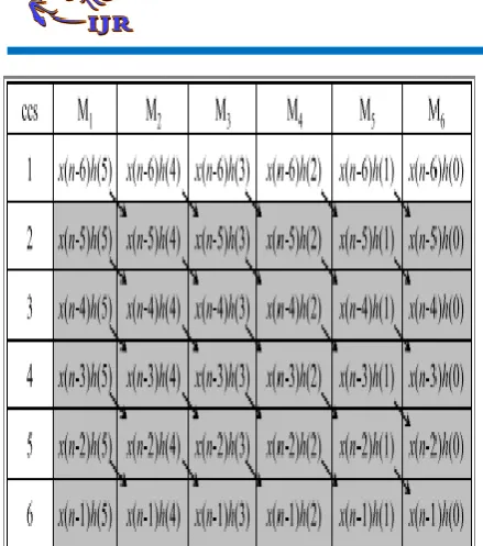
Fig. 2. (a) DFT of multipliers of DFG shown in Fig. 1(a) corresponding to output y(n). (b) DFT of multipliers of DFG shown in Fig. 1(b) corresponding to output y(n − 1). Arrow: accumulation path of the products.
a block of two successive outputs {y(n), y(n − 1)} that are derived from (2). The product values and their accumulation paths in DFG-1 and DFG-2 of Fig. 1 are shown in data- flow tables (DFT-1 and DFT-2) of Fig. 2. The arrows in DFT-1 and DFT-2 of Fig. 2 represent the accumulation path of the products. We find that five values of each column of DFT-1 are same as those of DFT-2 (shown in gray color in Fig. 2). These redundant computation of DFG-1 and DFG-2 can be avoided using non overlapped sequence of input blocks, as shown in Fig. 3. DFT-3 and DFT-4 of DFG-1 and DFG-2 for non overlapping input blocks are, respectively, shown in Fig. 3(a) and (b). As shown in Fig. 3(a) and (b), DFT-3 and DFT-4 do not involve redundant computation. It is easy to find that the entries in gray cells in DFT-3 and DFT-4 of Fig. 3(a) and (b) correspond to the output y(n), whereas the other entries of DFT-3 and DFT-4 correspond to y(n−1). The DFG of Fig. 1 needs to be transformed appropriately to obtain the computations according to DFT-3 and DFT-4.
B. DFG Transformation
The computation of DFT-3 and DFT-4 can be realized by DFG-3 of non overlapping blocks, as
Fig. 3. DFT of DFG-1 and DFG-2 for three non overlapped input blocks [x(n), x(n −1)], [x(n −2),
x(n −3)], and [x(n −4), x(n −5)]. (a) DFT-3 for computation of output y(n). (b) DFT-4 for
computation of output y(n − 1).
Fig. 4. Merged DFG (DFG-3: transpose form type-I configuration for block FIR structure).
it to block transpose form type-I configuration of block FIR filter. The DFG-3 can be retimed to obtain the DFG-4 of Fig. 5, which is referred to block transpose form type-II configuration. Note that both type-I and type-II configurations involve the same number of multipliers and adders, but type-II configuration involves nearly L times less delay elements than those of type-I configuration. We have, therefore, used block transpose form type-II configuration to derive the proposed structure.
C. Mathematical Formulation of the Transpose Form Block FIR Filter
Suppose in every cycle, the block FIR filter takes a block of L new input samples, and processes those to produce a block of L output samples. The kth block of filter output yk is computed using the relation
where the weight vector h is defined as
The input matrix Xk is defined as
where xki is the (i + 1)th column of Xk are defined as
Substituting (4) in (3), the matrix-vector product is expressed in the form of scalar–vector product as
Suppose N is a composite number and decomposed as N = M L, then index i is expressed as i = l + mL, for 0 ≤ l ≤ L − 1, and 0 ≤ m ≤ M − 1. Substituting i = l + mL in (5), we have
Substituting (7) in (4), we have
Substituting (8) in (3), we have
The input matrix Xk of (8) has an interesting feature. The data block x0
k is the current block, while {x0k−1, x0
k−2,..., x0k−M+1} are blocks delayed by 1, 2,...,(M − 1) cycles. The overlapped blocks {x1
k−1, x1k−2,..., x1
k−L+1} are, respectively, 1 clock cycle, 2 clock
cycles,...,(M − 1) cycles delayed version of overlapped block x1
k . To take the advantage of this feature, the input-matrix Xk is decomposed into M small matrices Sl
k , such that S0 k contains L input blocks {x0
k , x1k ,..., xL−1k }, and S1k contains input blocks {x0k−1, x1k−1,..., xL−1 k−1 }. Similarly, the input block {x0
k−M+1, x1 k−M+1,..., xL−1 k−M+1} constitute the matrix SM−1
k .
The coefficient vector h is also decomposed into small weight vectors cm = {h(mL), h(mL + 1), . . . , h(mL + L − 1)}. Interestingly, Smk is symmetric and satisfy the following identity:
According to (10), Sm
k (for 1 ≤ m ≤ M − 1) are m clock cycle delayed with respect to S0 k . Computation of (9) can be expressed in matrix-vector product using S0
k−m and cm as
The computations of (11) may be expressed in a recurrence form
where S0(z) and Y(z) are the z-domain representation of S0 k and yk , respectively. The DFG-4 of block transpose form type-II configuration (shown in Fig. 5 for N = 6 and L = 2) can be derived using the recurrence relation of (12). The delay operator {z−1} of (12) represents a delay for a block of data in the transpose form type-II structure that stores the product of S0
III. PROPOSED STRUCTURES
There are several applications where the coefficients of FIR filters remain fixed, while in some other applications, like SDR channelizer that requires separate FIR filters of different specifications to extract one of the desired narrowband channels from the wideband RF front end. These FIR filters need to be implemented in a RFIR structure to support multistandard wireless communication [6]. In this section, we present a structure of block FIR filter for such reconfigurable applications. In this section, we discuss the implementation of block FIR filter for fixed filters as well using MCM scheme.
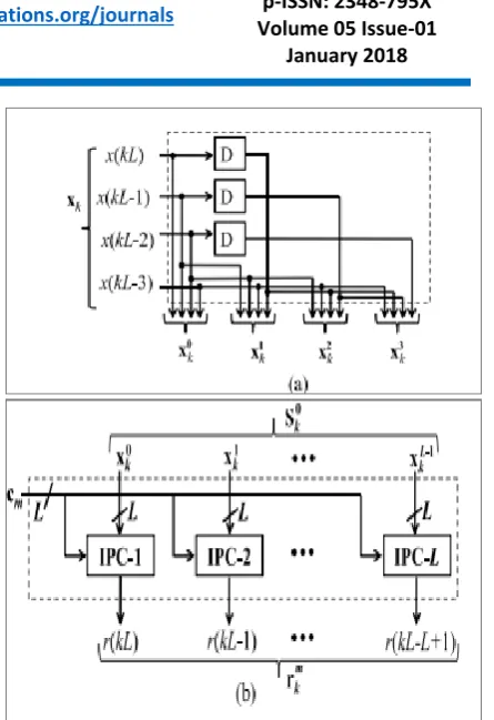
A. Proposed Structure for Transpose Form Block FIR Filter for Reconfigurable Applications
The proposed structure for block FIR filter is [based on the recurrence relation of (12)] shown in Fig. 6 for the block size L = 4. It consists of one coefficient selection unit (CSU), one register unit (RU), M number of inner product units (IPUs), and one pipeline adder unit (PAU). The CSU stores coefficients of all the filters to be used for the reconfigurable application. It is implemented using N ROM LUTs, such that filter coefficients of any particular channel filter are obtained in one clock cycle, where N is the filter length. The RU [shown in Fig. 7(a)] receives xk during the kth cycle and produces L rows of S0
k in parallel. L rows of S0k are transmitted to M IPUs of the proposed structure. The M IPUs also receive M short-weight vectors from the CSU
Fig. 6. Proposed structure for block FIR filter.
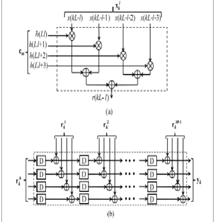
Fig. 7. (a) Internal structure of RU for block size L = 4. (b) Structure of (m + 1)th IPU.
such that during the kth cycle, the (m + 1)th IPU receives the weight vector cM−m−1 from the CSU and L rows of S0
k form the RU. Each IPU performs matrix-vector product of S0
k with the short-weight vector cm, and computes a block of L partial filter outputs (rm
k ). Therefore, each IPU performs L inner-product computations of L rows of S0
B. MCM-Based Implementation of Fixed-Coefficient FIR Filter
We discuss the derivation of MCM units for transpose form block FIR filter, and the design of proposed structure for fixed filters. For fixed-coefficient implementation, the CSU of Fig. 6
Fig. 8. (a) Internal structure of (l + 1)th IPC for L = 4. (b) Structure of PAU for block size L = 4. is no longer required, since the structure is to be tailored for only one given filter. Similarly, IPUs are not required. The multiplications are required to be mapped to the MCM units for a low-complexity realization. In the following, we show that the proposed formulation for MCM-based implementation of block FIR filter makes use of the symmetry in input matrix S0
k to perform horizontal and vertical common sub-expression elimination [17] and to minimize the number of shift-add operations in the MCM blocks. The recurrence relation of (12) can alternatively be expressed as
The M intermediate data vectors rm, for 0 ≤ m ≤ M − 1 can be computed using the relation
where R and C are defined as
To illustrate the computation of (14) for L = 4 and N = 16, we write it as a matrix product given by (16). From (16), we can observe that the input matrix contains six-input samples {x(4k), x(4k − 1), x(4k − 2), x(4k − 3), x(4k − 4), x(4k − 5), x(4k − 6)}, and multiplied with several constant coefficients, as shown in Table I. As shown in Table I, MCM can be applied in both horizontal and vertical direction of the coefficient matrix. The sample x(4k−3) appears in four rows or four columns of the following
input matrix:
larger saving in computational complexity. The proposed MCM-based structure for FIR filters for block size L = 4 is shown in Fig. 9 for the purpose of illustration. The MCM-based structure (shown in Fig. 9) involves six MCM blocks corresponding to six input samples. Each MCM block produces the necessary product terms as listed in Table I. The sub-expressions of the MCM blocks are shift added in the adder network to produce the inner-product values (rl,m), for 0 ≤ l ≤ L − 1 and 0 ≤ m ≤ (N/L) − 1 corresponding to the matrix product of (14). The inner-product values are finally added in the PAU of Fig. 8(b) to obtain a block of filter output.
IV.SIMULATION AND RESULTS
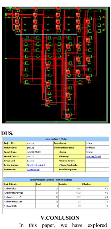
Implementation of FIR filter cores has been observed and we can see that fir filter cores have been implemented with both fixed and reconfigurable applications. Results have been taken in terms of area utilized, power dissipated and speed performance FIR filter have been designed in Verilog HDL and implemented using Xilinx 13.2 tool.
Simulation.
RTL Schematic.
Technology Schematic.
DUS.
V.CONLUSION
block direct-form structure has less ADP and less EPS than the proposed structure.
REFERENCES
[1] J. G. Proakis and D. G. Manolakis, Digital Signal Processing: Principles, Algorithms and Applications. Upper Saddle River, NJ, USA: Prentice-Hall, 1996. [2] T. Hentschel and G. Fettweis, ―Software radio receivers,‖ in CDMA Techniques for Third Generation Mobile Systems. Dordrecht, The Netherlands: Kluwer, 1999, pp. 257–283. [3] E. Mirchandani, R. L. Zinser, Jr., and J. B. Evans, ―A new adaptive noise cancellation scheme in the presence of crosstalk [speech signals],‖ IEEE Trans. Circuits Syst. II, Analog Digit. Signal Process., vol. 39, no. 10, pp. 681–694, Oct. 1995.
[4] D. Xu and J. Chiu, ―Design of a high-order FIR digital filtering and variable gain ranging seismic data acquisition system,‖ in Proc. IEEE Southeastcon, Apr. 1993, p. 1–6.
[5] J. Mitola, Software Radio Architecture: Object-Oriented Approaches to Wireless Systems Engineering. New York, NY, USA: Wiley, 2000. [6] A. P. Vinod and E. M. Lai, ―Low power and high-speed implementation of FIR filters for software defined radio receivers,‖ IEEE Trans. Wireless Commun., vol. 7, no. 5, pp. 1669–1675, Jul. 2006.
[7] J. Park, W. Jeong, H. Mahmoodi-Meimand, Y. Wang, H. Choo, and K. Roy, ―Computation sharing programmable FIR filter for low-power and high-performance applications,‖ IEEE J. Solid State Circuits, vol. 39, no. 2, pp. 348–357, Feb. 2004. [8] K.-H. Chen and T.-D. Chiueh, ―A low-power digit-based reconfigurable FIR filter,‖ IEEE Trans. Circuits Syst. II, Exp. Briefs, vol. 53, no. 8, pp. 617– 621, Aug. 2006.
[9] R. Mahesh and A. P. Vinod, ―New reconfigurable architectures for implementing FIR filters with low complexity,‖ IEEE Trans. Comput.-Aided Design Integr. Circuits Syst., vol. 29, no. 2, pp. 275–288, Feb. 2010.
[10] S. Y. Park and P. K. Meher, ―Efficient FPGA and ASIC realizations of a DA-based reconfigurable FIR digital filter,‖ IEEE Trans. Circuits Syst. II, Exp. Briefs, vol. 61, no. 7, pp. 511–515, Jul. 2014.
[11] P. K. Meher, ―Hardware-efficient systolization of DA-based calculation of finite digital convolution,‖ IEEE Trans. Circuits Syst. II, Exp. Briefs, vol. 53, no. 8, pp. 707–711, Aug. 2006. [12] P. K. Meher, S. Chandrasekaran, and A. Amira, ―FPGA realization of FIR filters by efficient and flexible systolization using distributed arithmetic,‖ IEEE Trans. Signal Process., vol. 56, no. 7, pp. 3009–3017, Jul. 2008.
[13] P. K. Meher, ―New approach to look-up-table design and memorybased realization of FIR digital filter,‖ IEEE Trans. Circuits Syst. I, Reg. Papers, vol. 57, no. 3, pp. 592–603, Mar. 2010.
[14] K. K. Parhi, VLSI Digital Signal Processing Systems: Design and Implementation. New York, NY, USA: Wiley, 1999.
[15] B. K. Mohanty and P. K. Meher, ―A high-performance energy-efficient architecture for FIR adaptive filter based on new distributed arithmetic formulation of block LMS algorithm,‖ IEEE Trans. Signal Process., vol. 61, no. 4, pp. 921–932, Feb. 2013.
[16] B. K. Mohanty, P. K. Meher, S. Al-Maadeed, and A. Amira, ―Memory footprint reduction for power-efficient realization of 2-D finite impulse response filters,‖ IEEE Trans. Circuits Syst. I, Reg. Papers, vol. 61, no. 1, pp. 120–133, Jan. 2014. [17] R. Mahesh and A. P. Vinod, ―A new common subexpression elimination algorithm for realizing low-complexity higher order digital filters,‖ IEEE Trans. Comput.-Aided Design Integr. Circuits Syst., vol. 27, no. 2, pp. 217–219, Feb. 2008.