Coordination Control of WPSS & PD
Controller to Time Dependent Stability
Analysis of Power System
Nitish Kumar1, Kumar Prabhakar2PG Student [Power System], Dept. of EX, IES College of Technology, Bhopal, Madhya Pradesh, India1
Assistant Professor, Dept. of EX, IES College of Technology, Bhopal, Madhya Pradesh, India2
ABSTRACT: This paper investigates the delay-dependent stability of a power system equipped with a wide-area damping controller (WADC) using a coordination control of WPSS & PD controller which consists of delay in wide area signals. Time delay in wide area signals would degrade system stability. To design a WADC, the controlled signal obtained by geometric approach for WPSS to damped out the inter-area oscillations and gain of the PSS is optimised by Genetic Algorithm (GA). Case study is undertaken based on a four-machine two-area power system to demonstrate the design principle and verify the feasibility of the proposed method.
KEYWORDS: Wide-Area Measurement System (WAMS), Wide-area Power System Stabilizer (WPSS), Proportional- Derivative (PD) controller, Genetic Algorithm (GA), Signal delay, Integral of Time Error (ITE).
I.INTRODUCTION
With growing electric power demand of modern era, the inter-area low frequency oscillations become a biggest problem for power system engineers and often suffer from poor system damping [1-3]. Many power systems on the globe has been affected by such type of inter-area oscillations whose frequency lie between 0.1 Hz to 1 Hz and sometimes these area oscillations causes blackout[4-5]. The conventional method to damp out such type of inter-area oscillations generally we installed Power System Stabilizer (PSS) at each generator which uses local signal such as rotor speed, accelerating power as a feedback signal. Such type of PSSs damped out the local mode oscillations effectively, but to damp out the inter-area oscillations their effectiveness is reduced. Because the inter-area modes are not controllable/Observable from local signals of the generator[6]
With the development of Phasor Measurement Unit (PMUs) in power system, Wide-Area Measurement System (WAMS) enable the remote signals as a feedback to design Wide-Area Damping Controller(WADC) to enhance the transient stability of the power system. The availability of remote signals can overcome the aforementioned shortcoming of lacking observability and provide flexibility to damp a special critical inter-area oscillation mode of power system[7]. The signals obtained from PMUs or remote signals contain information about overall network dynamics whereas local control signals lack adequate observability with regard to some of the significant inter-area mode. The real time information of synchronous phasor and sending the control signal to major control device (e.g. PSSs, HVDC controllers, FACTS based controllers) at high speed has now become easier due to the use of PMU [8].
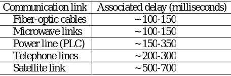
Table-I Time-delay for different communication links
Communication link Associated delay (milliseconds) Fiber-optic cables ~ 100-150
Microwave links ~ 100-150 Power line (PLC) ~ 150-350 Telephone lines ~ 200-300 Satellite link ~ 500-700
As even a very small delay can result in loss of power system stability [12], input delay cannot be neglected in controller design. For wide-area damping control, once the control location and feedback signal are selected, the path and mode of signal transmission are also fixed. Usually, this transmission path will not change in the short-term, so that Wide-area Power System Stabilizer (WPSS) input delay becomes stable. Thus, the delay can be modeled as a constant delay in controller design.
Although, WPSS provides a great potential to improve the damping inter-area oscillation, the delay caused by the transmission of remote signals will degrade the damping performance or may even cause instability of the closed loop system [11, 13]. Therefore, the influence of time delay must be fully taken into consideration in the controller design. Pade approximation [14-16] is the effective approach to deal with this kind of constant time delay problem. The major contribution of this paper is to design a wide area damping controller for inter-area oscillations damping and different (fixed value) latency compensation. At first, modal analysis of the linear model of power system excluding Wide-area is applied to find out the low-frequency oscillation modes and then identify the critical inter-area modes. Secondly, geometric approach has been used to select the most efficient wide-area signal. Then the controller gain is determined based on the Integral of Time Error (ITE) criterion and optimized by Genetic Algorithm.
This paper is divided into five sections. The first section is the introduction mentioning about the problem due to inter-area oscillations and signal delay. Section II describes the configuration of the study power system. Section III presents the modal analysis and selection of wide-area signals.Section IV describes design of WPSS. Simulation results and discussions are in section V and finally the conclusion is presented in section VI.
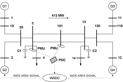
II. STUDY POWER SYSTEM
The test system under this research work is shown in figure-1[1]. The system consists of two symmetrical areas linked by two parallel tie-line of length 220 Km and 230 kV. Each area is equipped with two identical round rotor generators rated 20 kV/900 MVA. All four generators have identical parameters, except inertia coefficient (H), which are H = 6.5 s for Gen-1 and Gen-2 in area-1 and H = 6.175 s for Gen-3 and Gen-4 in area-2.
1
2 12
11 10 20 3
101 13
120 110 25 km 10 Km 110 Km 10 Km 25 Km G1 G2 G4 G3 L7 L9 413MW 110 Km
III .MODAL ANALYSIS AND SELECTION OF WIDE-AREA SIGNALS
The nonlinear dynamic model power system is usually described by a set of differential-algebraic equation. The whole power system excluding the local PSS and wide-area damping controller can be linearized at an equilibrium point.After linearization around a given operating condition and elimination of algebraicvariables, the state space model of studied system can be written as:
ẋ = Ax + Bu
y = Cx (1)
where x∈R × , u∈R × and y∈R × are the state, inputs and output vectors respectively. A∈R × , B∈R × and C∈R × are state, input and output matrices, respectively.
Modal analysis of linear model (1) is applied to find out the low-frequency oscillation modes and then identify the critcal inter-area mode with the help of geometric measures of modal controllability/observability.For the designing of WADC, selection of stabilizing signals and location of control sites is an important factor. Wide-area control is desirable for inter-area oscillations damping mainly because it provides better controllability and observability thus better damping effects of those modes because remote stabilizing signals have more information about system dynamics. In the selection of stabilizing signals and control locations, it is desirable to use as few measurements and control devices as possible to achieve satisfactory damping effects. The most often used method to select locations and stabilizing signals for PSSs devices is geometric measure of jointcontrollability/observability [17-18].
a) Geometric Approach
The geometric measure of controllability gm (k) and observability gm (k)associated with the mode kthare given by[19]
gm (k) = cos α(ψ , b ) = |ψb |
‖ψ ‖‖b‖ (2)
gm (k) = cos θ ϕ , c = cϕ
‖ϕ ‖ c (3)
In (2) and (3), b is the ih column of matrix B corresponding to ih input, c is the jh row of output matrix C
corresponding to jh output. |z|and‖z‖is the modulus and Euclidean norm of z respectively. α(ψ , b ) is geometrical
angle between input vector i and kh left eigenvector and θ ϕ , c geometric angle between the output vector j and kh right eigenvector.The joint controllability and observability index of geometric approach is defined by:
C = gm (k)∗gm (k) (4)
Table-II Dominant Inter-area Oscillations Modes (Without PSS)
The most stabilizing feedback signal selection was evaluated by geometric measure of controllability/observability approach. The candidate signals that are considered for the selection process are line active power and generator rotor speeds. In Table-III, The highest joint controllability/observability indices are indicated in bold and highest joint controllability/observability indices shown in Table-III suggest that the given inter area mode is efficiently controllable from Gen-2 and Gen-4 and are well observable from line active power flow of the tie-lineconnecting bus no. 3 to 101. Hence from geometric approach of signal selection the most stabilizing feedback signal is real tie-line power P3-101 and most effective generators for damping the inter area mode are Gen-2 and Gen-4
Table-III Geometric measure of controllability/observability approach for signal selection for mode-15 ( . ± . )
IV.DESIGN OF WIDE-AREA PSS
a) Structure of wide-area PSS
The wide-area PSS is designed to damp a critical inter-area oscillation mode-k by providing supplement damping control signal for excitation system of the ith generator, and the overall structure of a Wide-area PSS designed for multi-area interconnected power system is illustrated in Fig.-2.
Fig-2 Proposed structure of wide-area PSS
Mode No. Eigen Value Damping Ratio Frequency (Hz)
05. −0.25 ± 0.65i 0.36 0.10
15. 0.05 ± 4.1i -0.01 0.65
Signals
Generators
G-1 G-2 G-3 G-4
As shown in Fig.2, ‘d’ is the signal transmission delays between measurement location and wide-area PSS. The transfer function of wide-area PSS is:
H (s) = K sT
1 + sT
1 + sT
1 + sT (5)
Where TW is the washout constant and usually chosen as 5s- 10s, T1 and T2 are phase-compensation parameters, KW is the positive constant gain, m is the number of lead-lag compensation stages (usually equal to 2).The stabilizer gain KW determines the amount of damping introduced by the PSS. The signal washout block is a high pass filter, with time constant TW, which eliminates the low frequencies that are present in the speed signal and allows the PSS to respond only to speed changes. The phase compensation block is usually a single first order lead-lag transfer function or cascade of two first order transfer function used to compensate the phase lag between the excitation voltage and the electrical torque of the synchronous machine. The output is the stabilization voltage to connect to the input of the excitation system block used to control the terminal voltage of the synchronous machine.
b) Pade Approximation
The feedback signal delay of wide-area controller affects the control effect because the delay will introduce phase deviation at the input signal. Usually, for an oscillation mode with frequency off, the phase lag φintroduced by delay ‘ ’ can be obtained by
φ= 360fd (6)
For example, when the dominant frequency of a WPSS is 0.65 Hz, a delay of 100 ms will introduce a phase lag of
360 × 0.65 × 0.05 = 11.7 (Phase lag)
It can be seen from above that the phase lag introduced by delay is determined by both the delay itself and the oscillation frequency [20]. For the same delay, the corresponding phase lag is larger with the higher frequency, and vice versa. In MATLAB, time-delays are expressed in the exponential form ( e ) in the Laplace domain. It can be replaced by a first-order Pade Approximation [21]:
e ≈ (7)
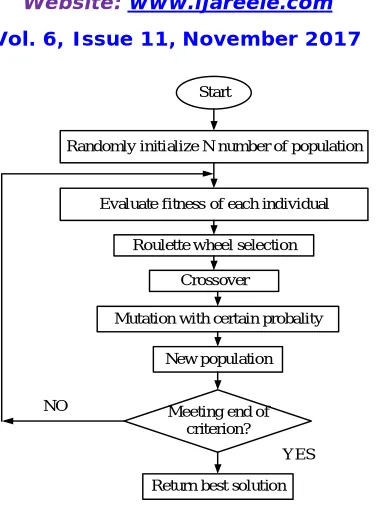
c) Optimization Method - Genetic Algorithm (GA)
Start
Randomly initialize N number of population
Evaluate fitness of each individual
Roulette wheel selection Crossover
Mutation with certain probality
New population
Meeting end of criterion?
Return best solution NO
YES
Fig. 3. Flow Chat for GA
The genetic algorithm begins with a set of solutions (represented by chromosomes) called the population. Solutions from one population are taken and used to form a new population. This is motivated by the possibility that the new population will be better than the old one. Solutions are selected according to their fitness to form new solutions (offspring); more suitable they are more chances they have to reproduce. This is repeated until some condition (e.g. number of populations or improvement of the best solution) is satisfied. The oscillation of a system can be seen through the tie-line active power deviation or speed deviation of rotor. To minimize the oscillation of any deviation is research objective. For kundur’s two area four machines system, integral of time error of speed deviation for G-2 and G-4 taken as a objective function (J)
J =∫ |∆ω|. t. dt (8)
where
t =simulation time range.
For a stipulated period of time, the time domain simulation of the above power system is worked out and from the simulation the calculation for the objective function is calculated. The prescribed range of the PSS and damping controller are limited in a boundary. Thus the following optimization problem is formulated from the above design approach.
Minimize J Subject to :
40≤K ≤70
0.001≤K ≤0.01
40≤K ≤70
0.001≤K ≤0.01 (9)
V. SIMULATION RESULTS AND DISCUSSION
Fig-4 Configuration of the generator with PSS
The structure of the Wide-area PSS is shown in Fig.-4. The Vt and Vref denote the generator terminal voltage and its reference. The local mode is damped by PSS which uses the rotor speed of local generator as input and its parameter is determined based on phase compensation of local mode frequency. The output of wide-area PSS is added to the excitation system of the selected machine together with the output of the local PSS to provide damping for the inter-area modes.
For the test system, G-2 of area-1and G-4 of area-2 are equipped with a LPSS and WPSS to damp the local mode oscillation as well as inter-area oscillations along with Proportional – Derivative (PD) controller. For this gain of LPSS and WPSS is optimized based on Integral of Time Error (ITE) criterion based on GA, considering different condition for signal delay and optimized value of gain tabulated in Table-IV. Rest of the parameter of LPSS and WPSS as follows at different condition of signal delay tabulated in Table-V. The parameters of PD controller arebased on hit &trail methodology and tabulated in Table- VI.
Table-IV Gain of PSS at different conditions of signal delay
Disturbance Delay (ms) Area-1 (G-2) Area-2 (G-4) LPSS WPSS LPSS WPSS Small 50 63.7662 0.0096 57.5580 0.0065 100 50.1133 0.0050 44.3484 0.0020 150 68.5843 0.0013 46.7144 0.0053
Table-V Different Parameters of LPSS & WPSS
Gen PSS
G-2,G-4 All are in second
Table-VI Different Parameters for PD controller (By Hit & Trial)
Proportional Controller Gain 0.8425
Derivative Controller Gain 0.4937
Small Signal Stability Assessment
To perform the dynamic analysis of the closed loop test system for Kundur two area four machine system as shown in fig -5, a small pulse with magnitude of 5% as a disturbance was applied to the generator G1 for 12 cycles.
Fig-5 Kundur's Two Area Four Machine System
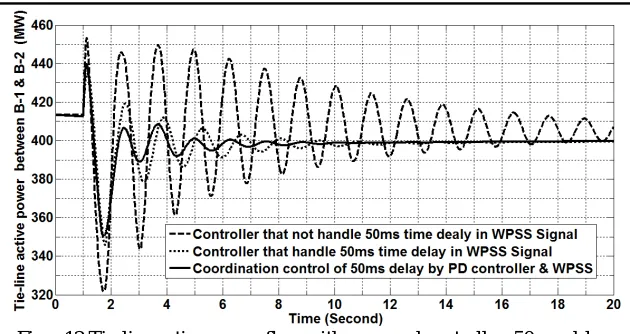
The simulation time was of 20 seconds. Then the response of tie-line active power flow from area-1 to area-2 and rotor angle deviation are examined by considering the test system with WPSS and LPSS under the presence of selected feedback signals by geometric approach and considered the effect of signal delay.
Fig – 7 Tie-line active power flow with 50ms time delay
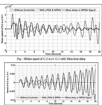
Fig – 8Rotor speed of G-2 w.r.t. G-1 with 50ms time delay
Fig –10 Tie-line active power flow with different time delay
Fig – 11Rotor speed of G-3 w.r.t. G-1 with different time delay
Fig – 13Tie-line active power flow with proposed controller, 100 ms delay
Fig – 13Tie-line active power flow with proposed controller, 150 ms delay
VI. CONCLUSION
In this research work, researcher designed the delay dependent WADC to damp out the inter-area oscillations. The proposed coordination control of WPSS and PD controller implemented with Kundur two area four machine system and some simulation results are carried out to verify the effectiveness of proposed controller under small disturbance. From the simulation results, it reveals that the proposed controller damps out the inter-area oscillations effectively under different delay conditions.
REFERENCES
[1] Kundur P., Power System Stability and Control. New York: McGraw- Hill, 1994.
[2] Aboul-Ela M. E., Sallam A. A., Mccalley J. D., and Fouad A. A.,“Damping controller design for power system oscillations using global signals,” IEEE Trans. Power Syst., vol. 11, no. 2, pp. 767–773, May 1996.
[3] Majumder R., Chaudhuri B., Pal B. C., and Zhong Q. C., “A unifiedSmith predictor approach for power system damping control design using remote signals,” IEEE Trans. Control Syst. Technol., vol. 13, no.6, pp. 1063–1068, Nov. 2005.
[4] Pal, B.C. “Robust Damping Control of Inter-Area Oscillations in Power System with Super-conducting Magnetic Energy Storage Devices ,” PhD thesis, Imperial college of Science Technology and Medicine, Department of Electrical & Electronics Engineering.
[5] Paserba J., ‘Analysis and Control of Power System Oscillation’ CIGRE special publication 2007, Technical Brochure 111.
[6] Zhang P., Messina A. R, Coonick A., and Cory B. J., “Selection of locations and input signals for multiple SVC damping controllers in large scale power systems,” in Proc. IEEE Power Eng. Soc. Winter Meeting,1998, pp. 667–670.
[7] J. L., Y. W., W. Q.h., W. J.y., C. S.j, “Delay-dependent stability for load frequency control with constant and time-varying delays,” IEEE Trans. on Power System, 27(2), 2012: 932-941.
[8] Kamwa, L. GérinLajoie, “State-Space System Identification-Toward MIMO Models for Modal Analysis and Optimization of Bulk Power Systems,” IEEE Trans. on Power Systems, vol. 15, no. 1, Feb. 2000,pp. 326-335.
[9] Kamwa, I. ; Hiniche, A.; Trudel, G.; Dobrescu, M.; Grondin, R.; and Lefebvre, D. – ‘Assessing the technical value of FACTS-based Wide-Area Damping Control Loops’ – IEEE Power Eng. Soc. General Meeting, Vol. 2, June 2005, pp. 1734-1743
[10] Tomsovic, K.; Bakken, D.E.; Venkatasubramanian, V.; and Bose, A.; - ‘Designing the Next Generation of Real-Time Control, Communication and Computations for large Power Systems’ – Proc. IEEE, Pub: IEEE, Vol. 93, No. 5, May 2005, pp. 965-979.
[11] NaduvathuparambilBiju, Valenti Matthew C., and Feliachi Ali, “Communication Delays in Wide-area Measurement Systems,” Proceedings of the Thirty-Fourth Southeastern Symposium on System Theory, pp.118- 122, 2002.
[12] Ela, Magdy E. Aboul; Sallam, A.A.; McCalley, James D.; and Found, A.A.; - ‘ Damping Controller Design For Power System Oscillations’ – IEEE Transaction on Power Systems, Pub: IEEE, Vol. 11, No. 2, May 1996, pp. 767-773.\
[13] Tomsovic, K.; Bakken, D.E.; Venkatasubramanian, V.; and Bose, A.; - ‘Designing the Next Generation of Real-Time Control, Communication and Computations for large Power Systems’ – Proc. IEEE, Pub: IEEE, Vol. 93, No. 5, May 2005, pp. 965-979.
[14] Chengshan W., Jie S., PSS designing with considering of time delay impact, Proceeding of the CSEE, 27(10), 2007:1-6.
[15] Daniel D., Aguinaldo S., Ildemar C., Wide-area measurements-based two-level control design considering signal transmission delay, IEEE Trans. on Power System,24(1), 2009: 208–216.
[16] Hua Y., Jian H., Yutian L., A method for computing eigenvalue of time-delayed power system based on pade approximation, Automation of Electric Power Systems, 37(7), 2013:25-30.
[17] Chaudhuri B., Pal.B.C., “Robust damping of inter-area oscillations through controllable phase shifters using global signals,” IEEE PES General Meeting, Vol. 3, pp.1673-1679, 13-17 July 2003.
[18] Martins N. and Lima L. T. G., “Determination of suitable locations for power system stabilizers and Static VAR Compensators for damping electromechanical oscillations in large scale power systems,” IEEE Trans. Power Syst., vol. 5, no. 4, pp. 1455–1469, Nov. 1990.
[19] Hamdan A. M. A. and Elabdalla A. M., “Geometric measures of modal controllability and observability of power systems models,”Elect. Power Syst. Res., vol. 15, pp. 147–155, 1988.
[20] Philipp L. D., MahmoodAusif, Philipp B. L., “An improved refinable rational approximation to the ideal time delay,” IEEE Trans. Circuits and Systems, vol. 46, pp. 637-640, May 1999.
[21] Ree J. D. L., Centeno V., Thorp J. S., and Phadke A. G., “Synchronized phasor measurement applications in power systems,” IEEE Trans. Smart Grid, vol. 1, no. 1, pp. 20–27, Jun. 2010.