A Single Phase Active Device for Power
Quality Improvement Using Fuzzy and Pi
Controller
Dr.K.Kumarasamy1, G.Susheenth2, K.Jeevagan3, A.Athil4
Associate Professor, Dept. of EEE, Vel Tech High Tech Dr.Rangarajan Dr.Sakunthala Engineering College Avadi,
Chennai, India1
Student, Dept. of EEE, Vel Tech High Tech Dr.Rangarajan Dr.Sakunthala Engineering College Avadi,
Chennai, India2,3,4
ABSTRACT: A transformerless hybrid series active filter along with pi controller and fuzzy controlleris proposed to
enhance the power quality in single-phase systems with critical loads. This paper assists the energy management and power quality issues related to electric transportation and focuses on improving electric vehicle load connection to the grid. The control strategy is designed to prevent current harmonic distortions of nonlinear loads to flow into the utility and corrects the power factor of this later. While protecting sensitive loads from voltage disturbances, sags, and swells initiated by the power system, ridded of the series transformer, the configuration is advantageous for an industrial implementation. This polyvalent hybrid topology allowing the harmonic isolation and compensation of voltage distortions could absorb or inject the auxiliary power to the grid. Aside from practical analysis, this paper also investigates on the influence of gains and delays in the real-time controller stability. The simulations and experimental results presented in this paper were carried out on a 2-kVA laboratory prototype demonstrating the effectiveness of the proposed topology.
KEYWORDS: Current harmonics, electric vehicle, hybrid series active filter (HSeAF), power quality, real-time
control.
I. INTRODUCTION
isolation series transformer had decelerated their industrial application in the distribution system. The second category was developed in concern of addressing voltage issues on sensitive loads commonly known as DVR, they have a similar configuration as the SeAF. These two categories are different from each other in their control principle. This difference relies on the purpose of their application in the system
The hybrid series active filter (HSeAF) was proposed to address the aforementioned issues with only one combination. Hypothetically, they are capable to compensate current harmonics, ensuring a power factor (PF) correction and eliminating voltage distortions at the PCC [11], [12]. These properties make it an appropriate candidate for power quality investments. The three-phase SeAFs are well documented [13], [14], whereas limited research works reported the single-phase applications of SeAFs in the literature. In this paper, a single phase transformerless HSeAF is proposed and capable of cleaning up the grid-side connection bus bar from current harmonics generated by a nonlinear load [15]. With a smaller rating up to 10%, it could easily replace the shunt active filter [16]. Furthermore, it could restore a sinusoidal voltage at the load PCC.
The advantage of the proposed configuration is that nonlinear harmonic voltage and current producing loads could be effectively compensated. The transformerless hybrid series active filter (THSeAF) is an alternative option to conventional power transferring converters in distributed generation systems with high penetration of renewable energy sources, where each phase can be controlled separately and could be operated independently of other phases [17]. This paper shows that the separation of a three-phase converter into single phase Hbridge converters has allowed the elimination of the costly
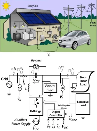
Fig. 1. (a) Schematic of a single-phase smart load with the compensator installation. (b) Electrical diagram of the THSeAF in a single-phase utility
and its considerations are briefly explained, and the voltage and current harmonic detection method is explicitly described. To evaluate the configuration and the control approach, some scenarios are simulated. Experimental results performed in the laboratory are demonstrated to validate simulations. This paper is summarized with a conclusion and appendix where further mathematical developments are demonstrated.
II. SYSTEM ARCHITECTURE
A. System Configuration
The THSeAF shown in Fig. 1is composed of an H-bridge converter connected in series between the source and the load. A shunt passive capacitor ensures a low impedance path for current harmonics. A dc auxiliary source could be connected to inject power during voltage sags. The dc-link energy storage
TABLE I
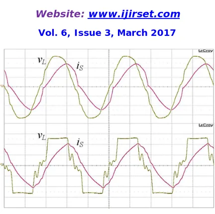
Fig. 2. Terminal voltage and current waveforms of the 2-kVA singlephase system without compensator. (a) Regular operation. (b) Grid’s voltage distortion (scales: 50 V/div for channel 1 and 10 A/div for channel 2).
system is described in [19]. The system is implemented for a rated power of 2200 VA. To ensure a fast transient response with sufficient stability margins over a wide range of operation, the controller is implemented on a dSPACE/dsp1103. The system parameters are identified in Table I. A variable source of 120 Vrms is connected to a 1.1-kVA nonlinear load and a 998-VA linear load with a 0.46 PF. The THSeAF is connected in series in order to inject the compensating voltage. On the dc side of the compensator, an auxiliary dc-link energy storage system is installed. Similar parameters are also applied for practical implementation.
TABLE II
SINGLE-PHASE COMPARISON OF THE THSeAF TO PRIOR HSeAFs
To emphasize the comparison table fairly, the equivalent single phase of each configuration is considered in the evaluation. Financial production evaluation demonstrated a 45% reduction in component costs and considerable reduction in assembly terms as well.
B. Operation Principle
The SeAF represents a controlled voltage source (VSI). In order to prevent current harmonics iLh to drift into
the source, this
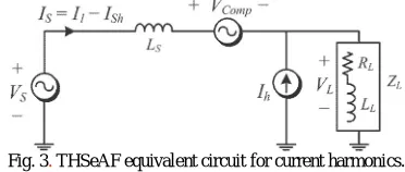
Fig. 3. THSeAF equivalent circuit for current harmonics.
series source should present low impedance for the fundamental component and high impedance for all harmonics as shown in Fig.3. The principle of such modeling is well documented in [20].
resistance representing the active power consumed and a current source generating current harmonics. Accordingly, the impedance ZL represents the nonlinear load and the inductive load.
The SeAF operates as an ideal controlled voltage source(V comp) having a gain (G) proportional to the current harmonics (Ish) flowing to the grid (Vs)
Vcomp = G.Ish − VLh. - (1)
This allows having individual equivalent circuit for the fundamental and harmonics
Vsource = Vs1 + Vsh, VL = VL1 + VLh - (2)
The source harmonic current could be evaluated
Vsh = − Zs.Ish + Vcomp + VLh - (3)
VLh =ZL(Ih − Ish). - (4)
Combining (3) and (4) leads to (5)
Ish =Vsh(G − Zs) . (5)
If gain G is sufficiently large (G→∞), the source current will become clean of any harmonics (Ish → 0). This will
help improve the voltage distortion at the grid side. In this approach, the THSeAF behaves as high-impedance open circuit for current harmonics, while the shunt high-pass filter tuned at the system frequency creates a low-impedance path for all harmonics and open circuit for the fundamental; it also helps for PF correction.
III. MODELING AND CONTROL OF THE SINGLE-PHASE THSeAF
A. Average and Small-Signal Modeling
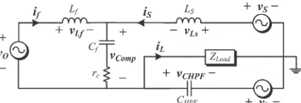
Based on the average equivalent circuit of an inverter [23],the small-signal model of the proposed configuration can be obtained as in Fig. 4. Hereafter, d is the duty cycle of the upper switch during a switching period, whereas ¯v and ¯i
denote the average values in a switching period of the voltage and current
Fig. 4.Small-signal model of transformerless HSeAF in series between the grid and the load.
are expressed by (6) and (7) as follows: ¯vO = (2d − 1_)VDC (6)
where the (2d −1) equals to m, then ¯iDC = m¯if . (7)
Calculating the Thévenin equivalent circuit of the harmonic current source leads to the following assumption: ¯vh(jω) = −j¯ih /CHPF · ωh . (8)
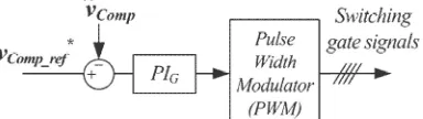
Fig. 5. Control system scheme of the active part
A dc auxiliary source should be employed to maintain an adequate supply on the load terminals. During the sag or swell conditions, it should absorb or inject power to keep the voltage magnitude at the load terminals within a specified margin. However,
if the compensation of sags and swells is less imperative, a capacitor could be deployed. Consequently, the dc-link voltage across the capacitor should be regulated as demonstrated
in Fig. 5
B. Voltage and Current Harmonic Detection
The outer-loop controller is used where a capacitor replaces the dc auxiliary source. This control strategy is well explained in the previous section. The inner-loop control strategy is based on an indirect control principle. A fast Fourier transformation was used to extract the magnitude of the fundamental and its phase degree from current harmonics. The control gain G representing the impedance of the source for current harmonics has a sufficient level to clean the grid from current harmonics fed through the nonlinear load.
The second proportional integrator (PI) controller used in the outer loop was to enhance the effectiveness of the controller when regulating the dc bus. Thus, a more accurate and faster transient response was achieved without compromising the compensation behavior of the system. According to the theory, the gain G should be kept in a suitable level, preventing the harmonics from flowing into the grid [22], [24]. As previously discussed, for a more precise compensation of current harmonics, the voltage harmonics should also be considered.
The compensating voltage for current harmonic compensation is obtained from
vcomp_i(t) = (−GˆiS + ˆvL)−[| − GiS1 + vL1| · sin(ωSt−θ)]. - (15)
Hereby, as voltage distortion at the load terminals is not desired, the voltage sag and swell should also be investigated in the inner loop. The closed-loop equation (16) allows to indirectly maintain the voltage magnitude at the load side equal to V ∗
L as a predefined value, within acceptable margins
vcomp_v = ˆvL − V∗L sin(ωSt). - (16)
The entire control scheme for the THSeAF presented in Fig. 5was used and implemented in MATLAB/Simulink for real-time simulations and the calculation of the compensating voltage. The real-time toolbox of dSPACE was used for compilation and execution on the dsp-1103 control board. The source and load voltages, together with the source current, are considered as system input signals. According to Srianthumrong et al. [25], an indirect control increases the stability of the system.
The source current harmonics are obtained by extracting the fundamental component from the source current The source current harmonics are obtained by extracting the fundamental component from the source current
V*com_ref = vcomp_v − vcomp_i + vDC_ref - (17)
where the vDC_ref is the voltage required to maintain the dc bus voltage constant vDC_ref (t) = VO_DC · sin(ωSt). -(18)
A phase-locked loop was used to obtain the reference angular frequency (ωs). Accordingly, the extracted current
harmonic contains a fundamental component synchronized with the source voltage in order to correct the PF. This current represents the reactive power of the load. The gain G representing the resistance for harmonics converts current into a relative voltage. The generated reference voltage vcomp_i required to clean the source current from harmonics is
described in (15).
According to the presented detection algorithm, the compensated reference voltage v∗Comp_ref is calculated.
Thereafter, the reference signal is compared with the measured output voltage and applied to a PI controller to generate the corresponding gate signals as in Fig. 6.
C. Stability Analysis for Voltage and Current Harmonics
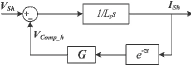
The stability of the configuration is mainly affected by the introduced delay of a digital controller. This section studies the impact of the delay first on the inclusive compensated system according to works cited in the literature. Thereafter, its effects on the active compensator is separated from the grid. Using purely inductive source impedance (see Fig. 4) and Kirchhoff’s law for harmonic frequency components, (19) is derived. The
delay time of the digital controller, large gain G, and the high stiffness of the system seriously affect the stability of the closed-loop controlled system
Fig. 8. Closed-loop control diagram of the active filter with a constant delay timeτ.
Ish(s) =(Vsh − VComp – VLh)/Lss -(19)
The compensating voltage including the delay time generated by the THSeAF in the Laplace domain [see (1)] is
vComp = G · Ish · e−τs − VLh. - (20)
Considering (19) and (20), the control diagram of the system with delay is obtained as in Fig. 7.
For the sake of simplicity, the overall delay of the system is assumed to be a constant value τ . Therefore, the open-loop transfer function is obtained
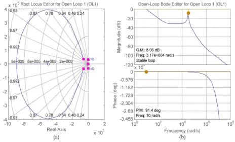
A PI controller with system parameters described in Table I demonstrates a smooth operation in the stable region. By means of MATLAB, the behavior of the system’s transfer function F(s) is traced in Fig.9. The root locus and the Bode diagram of the compensated open-loop system demonstrate a gain margin of 8.06 dB and a phase margin of 91◦. Furthermore, for an extra theoretical investigation, the influence of the delay on the load voltage could also be evaluated with regard to the transfer function TV _LS(s)
Fig. 9. Compensated open-loop system with delay time of 40 μs. (a) Root locus diagram. (b) Bode diagram
IV. SIMULATIONS AND EXPERIMENTAL RESULTS
The proposed transformerless-HSeAF configuration was simulated in MATLAB/Simulink using discrete time steps of Ts = 10 μs. A dSPACE/dsp1103 was used for the fast control prototyping. To ensure an error-free and fast implementation, the complete control loop was executed every 40 μs. The parameters are identified in Table I.
The combination of a single-phase nonlinear load and a linear load with a total rated power of 2 kVA with a 0.74 lagging PF is applied for laboratory experiments and simulations. For experiments and simulations, a 2-kVA 120-Vrms 60-Hz variable source is used. THSeAF connected in series to the system compensates the current harmonics and voltage distortions. The complete simulation of the system is demonstrated in the simulation diagram in Fig. 10.
A gain G = 8 Ω equivalent to 1.9 p.u. was used to control current harmonics. As mentioned earlier, the capability of operation with low dc voltage is considered as one of the main advantages of the proposed configuration. For this experiment,
demonstrates improvement in the source current THD. The load terminal voltage VL THD is 4.3%, while the source
voltage is highly distorted (THD VS = 25%).
Fig 10. Simulation diagram
Experimental results obtained in the laboratory corroborate the successful operation of the THSeAF shown in simulations. Figs. 12 and 13 show the compensator during steady state operating with parameters described in Table I. The source current became sinusoidal, and the load voltage was regulated at rated 120 Vrms. The source current is in phase with the utility voltage, achieving a unity PF correction. The grid supplies 1.545 kVA at a PF equal to 0.99, while the load consumes 2 kVA with a PF of 0.75.
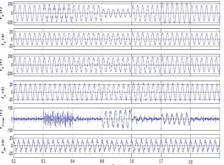
Fig. 11. Simulation of the system with the THSeAF compensating current harmonics and voltage regulation. (a) Source voltage vS, (b) source current
iS, (c) load voltage vL, (d) load current iL, (e) active-filter voltage VComp, and (f)harmonics current of the passive filter iPF.
Fig. 12. Experimentalwaveforms and harmonic spectrumunder steadystate sinusoidal grid voltage. (a) Source voltage vS [50 V/div], (b) source current iS [10 A/div], (c) load terminal voltage vL [50 V/div], (d) load current iL [10 A/div], (e) THSeAF voltage vComp [20 V/div], (f) passive filter
current iPF [10 A/div], and (g) dc voltage vDC [50 V/div].
The experimented results illustrate a high fidelity with results observed in simulation. Therefore, the
Fig. 13. Waveforms during a variation of the source voltage. (a) Source voltage vS [50 V/div], (b) source current iS [10 A/div], (c) load PCC voltage
TABLE III
LABORATORY MEASURED VALUE AND POWER FLOW ANALYSIS
system is subjected to sag and swells initiated from the utility source as shown in the following figures. While cleaning the source current from harmonics and correcting the PF, the compensator regulates
the load terminal voltage. Clarified in Section III, the auxiliary source provides the necessary amount of power to maintain the supply at the load terminals despite variation in the source magnitude. The behavior of the proposed compensator during dynamic load variation could be depicted from Fig.14, where the load is suddenly changed
The THSeAF reacts instantly to this variation and does not interfere its operation functionality. Meanwhile, it is normal to observe a slight transient voltage variation depending on the momentum of the load disengagement or connection. To evaluate the compensator during utility perturbation, the power source became distorted as depicted in Fig. 15. The source current became cleaned of the majority of harmonics available in the load current and has a unity PF. The THSeAF prevents existing perturbation on the grid’s voltage to propagate on the load PCC. It protects sensitive loads and maintains a sinusoidal and regulated voltage across the PCC of loads with a
3.9% of distortion. Moreover, in a worst possible scenario, the already distorted utility’s voltage is subjected to voltage magnitude variation. Thus, the compensator should also inject power to maintain the load PCC voltage regulated at the desired level.
Fig. 14. Waveforms during a dynamic load variation. (a) Source voltage vS [50 V/div], (b) source current iS [10 A/div], (c) load PCC voltage vL [50 V/div], and (d) load current iL [10 A/div].
Fig. 15. Experimental waveforms under utility voltage distortion and prolonged sags. (a) Utility source voltage vS [50 V/div], (b) utility current iS [10 A/div], (c) load PCC voltage vL [50 V/div], and (d) load current iL [10 A/div].
V. SUMMARY
In this paper, a transformerless HSeAF along with pi controller and fuzzy controller, for power quality improvement was developed and tested. The paper highlighted the fact that, with the ever increase of nonlinear loads and higher exigency of the consumer for a reliable supply, concrete actions should be taken into consideration for future smart grids in order to smoothly integrate electric car battery chargers to the grid. The key novelty of the proposed solution is that the proposed configuration could improve the power quality of the system in a more general way by compensating a wide range of harmonics current, even though it can be seen that the THSeAF regulates and improves the PCC voltage. Connected to a renewable auxiliary source, the topology is able to counteract actively to the power flow in the system. This essential capability is required to ensure a consistent supply for critical loads. Behaving as high-harmonic impedance, it cleans the power system and ensures a unity PF. The theoretical modeling of the proposed configuration was investigated. The proposed transformerless configuration was simulated and experimentally validated. It was demonstrated that this active compensator responds properly to source voltage variations by providing a constant and distortion-free supply at load terminals. Furthermore, it eliminates source harmonic currents within a short period with the help of fuzzy controller and improves the power quality of the grid without the usual bulky and costly series transformer.
REFERENCES
[1] L. Jun-Young and C. Hyung-Jun, “6.6-kW onboard charger design using DCM PFC converter with harmonic modulation technique and two-stage dc/dc converter,” IEEE Trans. Ind. Electron., vol. 61, no. 3, pp. 1243– 1252, Mar. 2014.
[2] R. Seung-Hee, K. Dong-Hee, K. Min-Jung, K. Jong-Soo, and L. Byoung- Kuk, “Adjustable frequency duty-cycle hybrid control strategy for fullbridge series resonant converters in electric vehicle chargers,” IEEETrans. Ind. Electron., vol. 61, no. 10, pp. 5354–5362, Oct. 2014.
[3] P. T. Staats, W. M. Grady, A. Arapostathis, and R. S. Thallam, “A statistical analysis of the effect of electric vehicle battery charging on distribution system harmonic voltages,” IEEE Trans. Power Del., vol. 13, no. 2, pp. 640–646, Apr. 1998.
[4] A. Kuperman, U. Levy, J. Goren, A. Zafransky, and A. Savernin, “Battery charger for electric vehicle traction battery switch station,” IEEE
[5] Z. Amjadi and S. S. Williamson, “Modeling, simulation, control of an advanced Luo converter for plug-in hybrid electric vehicle energy-storage system,” IEEE Trans. Veh. Technol., vol. 60, no. 1, pp. 64–75, Jan. 2011.
[6] H. Akagi and K. Isozaki, “A hybrid active filter for a three-phase 12-pulse diode rectifier used as the front end of a medium-voltage motor drive,”
IEEE Trans. Power Del., vol. 27, no. 1, pp. 69–77, Jan. 2012.
[7] A. F. Zobaa, “Optimal multiobjective design of hybrid active power filters considering a distorted environment,” IEEE Trans. Ind. Electron., vol. 61, no. 1, pp. 107–114, Jan. 2014.
[8] D. Sixing, L. Jinjun, and L. Jiliang, “Hybrid cascaded H-bridge converter for harmonic current compensation,” IEEE Trans. Power Electron., vol. 28, no. 5, pp. 2170–2179, May 2013.
[9] M. S. Hamad, M. I. Masoud, and B. W. Williams, “Medium-voltage 12-pulse converter: Output voltage harmonic compensation using a series APF,” IEEE Trans. Ind. Electron., vol. 61, no. 1, pp. 43–52, Jan. 2014.
[10] J. Liu, S. Dai, Q. Chen, and K. Tao, “Modelling and industrial application of series hybrid active power filter,” IET Power Electron., vol. 6, no. 8, pp. 1707–1714, Sep. 2013.
[11] A. Javadi, H. Fortin Blanchette, and K. Al-Haddad, “An advanced control algorithm for series hybrid active filter adopting UPQC behavior,” in
Proc.38th Annu. IEEE IECON, Montreal, QC, Canada, 2012, pp. 5318–5323.
[12] O. S. Senturk and A. M. Hava, “Performance enhancement of the singlephase series active filter by employing the load voltage waveform reconstruction and line current sampling delay reduction methods,” IEEETrans. Power Electron., vol. 26, no. 8, pp. 2210–2220, Aug. 2011. [13] A. Y. Goharrizi, S. H. Hosseini, M. Sabahi, and G. B. Gharehpetian, “Three-phase HFL-DVR with independently controlled phases,” IEEE
Trans. Power Electron., vol. 27, no. 4, pp. 1706–1718, Apr. 2012.
[14] H. Abu-Rub, M. Malinowski, and K. Al-Haddad, Power Electronics for Renewable Energy Systems, Transportation, Industrial Applications. Chichester, U.K.: Wiley InterScience, 2014.
[15] S. Rahmani, K. Al-Haddad, and H. Kanaan, “A comparative study of shunt hybrid and shunt active power filters for single-phase applications: Simulation and experimental validation,” Math. Comput. Simul., vol. 71, no. 4–6, pp. 345–359, Jun. 19, 2006.
[16] W. R. Nogueira Santos et al., “The transformerless single-phase universal active power filter for harmonic and reactive power compensation,”
IEEETrans. Power Electron., vol. 29, no. 7, pp. 3563–3572, Jul. 2014.
[17] A. Javadi, H. Fortin Blanchette, and K. Al-Haddad, “A novel transformerless hybrid series active filter,” in Proc. 38th Annu. IEEE IECON, Montreal, QC, USA, 2012, pp. 5312–5317.
[18] H. Liqun, X. Jian, O. Hui, Z. Pengju, and Z. Kai, “High-performance indirect current control scheme for railway traction four-quadrant converters,” IEEE Trans. Ind. Electron., vol. 61, no. 12, pp. 6645–6654, Dec. 2014.
[19] E. K. K. Sng, S. S. Choi, and D. M. Vilathgamuwa, “Analysis of series compensation and dc-link voltage controls of a transformerless selfcharging dynamic voltage restorer,” IEEE Trans. Power Del., vol. 19, no. 3, pp. 1511–1518, Jul. 2004.
[20] H. Fujita and H. Akagi, “A practical approach to harmonic compensation in power systems-series connection of passive and active filters,” IEEE
Trans. Ind. Appl., vol. 27, no. 6, pp. 1020–1025, Nov./Dec. 1991.
[21] A. Varschavsky, J. Dixon, M. Rotella, and L. Mora, “Cascaded nine-level inverter for hybrid-series active power filter, using industrial controller,” IEEE Trans. Ind. Electron., vol. 57, no. 8, pp. 2761–2767, Aug. 2010.
[22] X. P. n. Salmero and S. P. n. Litra, “A control strategy for hybrid power filter to compensate four-wires three-phase systems,” IEEE Trans.
PowerElectron., vol. 25, no. 7, pp. 1923–1931, Jul. 2010.
[23] B. Singh, A. Chandra, and K. Al-Haddad, Power Quality Problems and Mitigation Techniques. Chichester, U.K.: Wiley, 2015.
[24] P. Salmeron and S. P. Litran, “Improvement of the electric power quality using series active and shunt passive filters,” IEEE Trans. Power Del., vol. 25, no. 2, pp. 1058–1067, Apr. 2010.
[25] S. Srianthumrong, H. Fujita, and H. Akagi, “Stability analysis of a series active filter integrated with a double-series diode rectifier,” IEEE
![Fig. 13. Waveforms during a variation of the source voltage. (a) Source voltage vS [50 V/div], (b) source current iS [10 A/div], (c) load PCC voltage vL [50 V/div], and (d) load current iL [10 A/div]](https://thumb-us.123doks.com/thumbv2/123dok_us/1613737.1200136/11.595.190.408.164.407/waveforms-variation-voltage-source-voltage-current-voltage-current.webp)
![Fig. 15. Experimental waveforms under utility voltage distortion and prolonged sags. (a) Utility source voltage vS [50 V/div], (b) utility current iS [10 A/div], (c) load PCC voltage vL [50 V/div], and (d) load current iL [10 A/div]](https://thumb-us.123doks.com/thumbv2/123dok_us/1613737.1200136/13.595.193.402.164.449/experimental-waveforms-utility-distortion-prolonged-utility-utility-current.webp)
