Performance Analysis of A PI Controller and A
Fuzzy Controller for Single Phase Shunt Active
Power Filter
Anu Wilson P1, Dr. E A Jasmin2
M Tech Student, Dept of Electrical and Electronics, Govt Engineering College Thrissur, Kerala, India1
Assistant Professor, Dept of Electrical and Electronics, Govt Engineering College Thrissur, Kerala, India2
ABSTRACT: Recent wide spread applications of power electronic equipments have caused an increase of the harmonic disturbances in the power systems. The nonlinear loads draw harmonic and reactive power components from AC mains. Here a PI controlled shunt active power filter and fuzzy controlled shunt active power filter are presented to eliminate harmonics and to compensate the reactive power of single phase rectifier. The performances of both controllers are analyzed from the simulation results obtained.
KEYWORDS:Active power filter, PI controller, Fuzzy Controller, Hysteresis Current Controller
I. INTRODUCTION
Power quality has become a research topic in power distribution systems due to a significant increase of harmonic pollution caused by proliferation of nonlinear loads, rectifiers, switching power supplies, and other line connected power converters. Harmonic pollution in electrical networks cause voltage distortion, additional losses and heating in electrical equipments, perturbing torque, vibrations and noise in motors, malfunction and failures of sensitive equipment, resonances and interference with electronic equipment and premature ageing[8] .
Traditionally passive inductance-capacitance (LC) filters have been used to eliminate the current harmonics and to improve the power factor. However, passive LC filters are bulky, load dependent and inflexible. They can also cause resonance to the system [9]. For instance, shunt active filters are known to be an appropriate means of eliminating harmonic contamination created by nonlinear loads [5].
Active power filters can be divided into single phase and three phase active filters. Single phase APFs have attracted less attention than three phase APFs because they are limited to low power applications. However, installing low power single phase APF near each single phase non-linear load may be sometimes a better solution than installing one medium power three phase APF at the point of common coupling due to simplicity of control without complex heavy mathematical equations and decreasing cost of APF from medium to low power.
Outputs of control circuit are the gating signals for the power switches. To indicate the steady state and transient performance, some simulation results are presented.
II. SINGLEPHASESHUNTACTIVEPOWERFILTER
Fig 1. The Shunt Active Power Filter
Shunt active power filters can be classified depending on inverter types as a current source inverter (CSI) or a voltage source inverter (VSI). In this study a single phase shunt active power filter which is also known as a VSI has been used. The shunt active power filter comprises a DC capacitor, semiconductor switches and a line inductor. Figure 1 illustrates the structure of a shunt active power filter. Shunt active power filters compensate load current harmonics by injecting equal but opposite harmonic compensating current. In this case the shunt active power filter operates as a current source injecting the harmonic components generated by the load but phase shifted by 180°.Thus the source current is forced by the current components to be in sinusoidal waveform. The relationship between these currents is given in Equation 1.
IC=IL-IS (1)
III.CONTROLOPERATIONOFINVERTER
A. Reference Current Generation
In order to determine harmonic and reactive component of load current, reference source current generation is needed. Thus, reference filter current can be obtained when it is subtracted from total load current. For better filter performance, generation of reference source current should be done properly. For this purpose several methods such as pq-theory, dq-transformation, multiplication with sine function and Fourier transform can be used. Here Fourier transform is used for extraction of reference source current. This method requires very less computation time compared to the other methods.
When a signal is expanded using Fourier series, we have fundamental component and harmonics. As we need to supply harmonics only, the filter has to supply load current minus fundamental. So by Fourier series, we calculate the fundamental first and then it is subtracted from load current to give reference current for active filter
.
B. DC Bus Voltage Control
The DC side capacitor serves two main purposes: (i) it maintains a DC voltage with small ripple in steady state, and (ii) serves as an energy storage element to supply real power difference between load and source during the transient period. In the steady state, the real power supplied by the source should be equal to the real power demand of the load plus a small power to compensate the losses in the active filter. Thus, the DC capacitor voltage can be maintained at a reference value. However, when the load condition changes the real power balance between the mains and the load will be disturbed. This real power difference is to be compensated by the DC capacitor. This changes the DC capacitor voltage away from the reference voltage. In order to keep satisfactory operation or the active filter, the peak value of the reference current must be adjusted to proportionally change the real power drawn from the source. This real power charged/discharged by the capacitor compensates the real power consumed by the load. If the DC capacitor voltage is recovered and attains the reference voltage, the real power supplied by the source is supposed to be equal to that consumed by the load again.
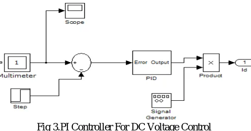
1. PI Controller
The PI controller consists of a proportional term and an integral term. Proportional value determines the reaction to the current error; the Integral determines the reaction based on the sum of recent errors. Kp and Ki are the proportional and the integral gains of the dc bus voltage PI controller.
Fig 3.PI Controller For DC Voltage Control
Here the values of proportional and integral gain taken as Kp=10, Ki=0.1. PI controller has been widely used for DC bus voltage regulation in shunt active power filters. This operation has been performed by comparing the real DC bus voltage of the active power filter with a reference DC bus voltage. Difference between two values is error signal applied to PI controller input. The PI controller output is active component added to the active component of load current. Thus the filter losses have been supplied from the grid in steady state and power balance between the grid and the load has been protected in transient state.
PI controller need a precise mathematical model of the system otherwise the control operation of PI controller is not efficient and accurate. If there are any changes occurring in the system, the existing PI controller in the system is not able to provide sufficient control of dc capacitor voltage and as a result the THD value is not reduced.
2. Fuzzy Controller
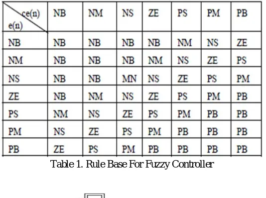
function the 49 ‘IF THEN’ rules were generated. Output of fuzzy controller is active component added to the active component of load current which a crisp number and it is obtained by using Centroid method. The rule base of the fuzzy controller is given in Table I.
Table 1. Rule Base For Fuzzy Controller
Fig 4. Fuzzy Logic Based DC Voltage Controller
Fig 5. Fuzzy Controller
positive big (PB), positive medium (PM) and positive small (PS). Figure 6 depicts the membership functions of inputs, while the membership functions of output variable are shown in Figure 7
.
Fig 6. Membership Functions of Inputs Fig 7.Membership Functions of Output
The advantages of fuzzy controllers are that they do not require an accurate mathematical model; it can work with imprecise inputs, can handle non-linearity, and are more robust than conventional controllers.
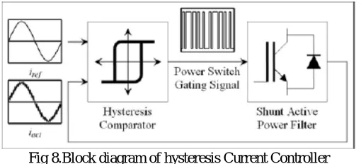
C. Hysteresis Current Controller
The third stage of the shunt APF control circuit is generating appropriate gating signals for the power switches that forces the filter current follow derived reference current. The goal is to reduce the current error. In this paper, hysteresis band current control method is used because implementation of this control is not expensive and the dynamic answer is excellent. It allows a fast current control. Unfortunately, in this control it is not possible to fix the commutation frequency. However, this disadvantage is not ever critical and current controllers based on this method are now standard in most APF control schemes
.
Fig 8.Block diagram of hysteresis Current Controller
The operating principle of the hysteresis band current controller which is shown in Fig. 8, depends on comparing of measured APF output current with its reference by the hysteresis comparator. The outputs of the comparator are the power switch gating signals.
IV.SIMULATIONSTUDY
The simulation circuit has been developed in a Matlab/Simulink/simpower tool to prove the validation of the proposed technique. The system parameters used for simulation are given in Table 2 and the simulation diagram is shown in figure 9.
Table 2.Simulation Parameters Fig 9.Simulation Diagram of the System
V. PERFORMANCEANALYSIS
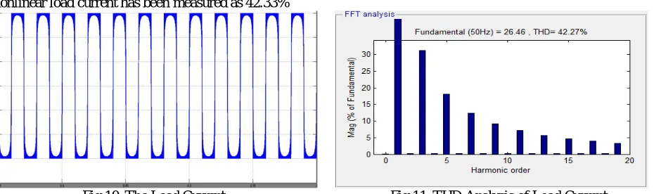
In this study, waveform of the grid voltage has been assumed as a pure sinusoidal. Figure 10 illustrates the waveform of the load current and the THD analysis of the load current is given in Figure 11 before connection of shunt active power filter. The load current is equal to the mains current before the connection of the active power filter and the THD ratio of a nonlinear load current has been measured as 42.33%
Fig 10. The Load Current Fig 11. THD Analysis of Load Current
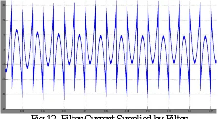
After connecting PI controller based SAF, the THD of the source current is reduced from 42.27% to 1.64%. Fig 12 shows the filter current supplied by filter. The waveform of the source current is shown in Figure 13, while Figure 14 illustrates the THD analysis of the source current.
Fig 12. Filter Current Supplied by Filter
Fig 13. Source Current with SAF Fig 14.THD Analysis of Source Current
B.Fuzzy Controller
Fuzzy logic based SAF reduces the THD of the source current from 42.27% to 0.86%.Filter current supplied by SAF is shown in figure 15. The waveform of the source current is shown in Figure 16 while Figure 17 illustrates the THD analysis of the source current.
Fig 16.Source Current with SAF Fig 17.THD Analysis of Source Current
The above result shows that THD gets reduced significantly on using a fuzzy controller than with the conventional PI controller.
When sudden changes occur in the system, the PI controller alone is not sufficient for controlling the dc capacitor voltage. But in the case of fuzzy controller, the THD level reduces below the IEEE standard
.
VI CONCLUSION
The harmonics caused by nonlinear loads result in low power factor and losses in power systems. To minimize this problem, shunt active power filters have been used. A PI controlled shunt active filter and fuzzy controlled shunt active filter are presented in the paper. From the simulation results it is clear that THD has been reduced from 42.27% to 1.64% in case of PI controller and to 0.86% in case of fuzzy controller .So fuzzy controller is able to provide much better performance than PI controller under varying load condition.
REFERENCES
[1] S.K. Jain, P. Agrawal, H.O. Gupta,“Fuzzy Logic Controlled Shunt Active Power Filter for Power Quality Improvement”, IEE P-Elect. Pow. Appl.,
Vol. 149, No. 5, pp. 317-328, 2002
[2] [2] W.M. Grady, S. Santoso, “Understanding Power System Harmonics”, IEEE Power Engineering Review, Vol. 21, No.11, pp. 8- 11, 2001.
[3] I. Colak, R. Bayindir, O. Kaplan, “Simulation of the DC Capacitor Voltage Controlled Single Phase Shunt Active Power Filters for Power Quality
Improvement”, G.U. J Sci, Vol. 23, No. 2, pp. 177-186, 2010.
[4] Ilhami ColakRamazan Bayindir, Orhan Kaplan,Ferhat Tas”DC Bus Voltage Regulation of an Active Power Filter Using a Fuzzy Logic Controller”
2010 Ninth International Conference on Machine Learning and Applications
[5] H. Akagi, “New Trends in Active Filters for Power Conditioning”,IEEE Transactions on Industry Applications, Vol. 32, No. 6, pp. 1312-1322, 1996.
[6] S. Rahmani, K. Al-Haddad, H.Y. Kanaan, “A Comparative Study of Shunt Hybrid and Shunt Active Power Filters for Single-Phase Applications:
Simulation and Experimental Validation”, Math. Comput.Simulat. Vol. 71, No. 4, pp. 345-349, 2006.
[7] D. Rivas, L. Moran, J. Dixon, J. Espinoza, “A Simple Control Scheme for Hybrid Active Power Filter”, IEE Proc.-Generation, Transmission and
Distribution, vol. 149, July 2002, pp. 485-490.
[8] J.S. Subjak, J.S. Mcquilin, “Harmonics-Causes, Effects, Measurements and Analysis”, IEEE Transactions on IndustryApplications, Vol. 26, No. 6,
pp. 1034-1042, 1990.