Automatic Railway Gate Control & Power
Generation
Ashvini Sherwade 1, Ashwini Pawar 2, Bhagyashree Ghadge 3, Deepika Srivastava 4
U.G. Student, Department of Electrical Engineering, JSPM’S (BSIOTR) Engineering College Pune, India1
U.G. Student, Department of Electrical Engineering, JSPM’S (BSIOTR) Engineering College Pune, India2
U.G. Student, Department of Electrical Engineering, JSPM’S (BSIOTR) Engineering College Pune, India3
Assistant Professor, Department of Electrical Engineering, JSPM’S (BSIOTR)Engineering College, Pune, India4
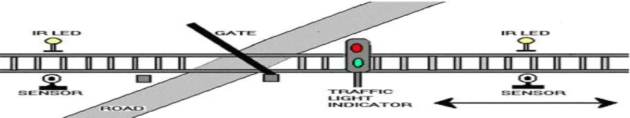
ABSTRACT: In our paper we are minimizing accident of level crossing between the railroads & highway. This types of accidents are happens due to the miss communication of workers. So, to overcome this difficulty we are implementing this project. In this paper PIC16F877A microcontroller is used to minimize the human effort & control the whole circuit. Two types of sensors is used & output of the first IR sensor are placed near to gate it receives the signal from arrival of the train then send output signal to microcontroller. Microcontroller output to motor driver then motor rotates in clockwise direction, then gate is close. Second sensor is placed another side of gate those are sense departure of the train & send signal to microcontroller. Microcontroller send signal to motor driver, motor rotates in anticlockwise direction & gate is open. Also to generate the power with the help of mounting the motor at base of the train. Motor shaft is take outside placed at track of rail through pulley. When train is running at that time shaft is also rotating at same speed & power is generated. Generated power is store in battery for run the train.
KEYWORS: IR Sensor, Microcontroller, DC Generator, L293D.
I. INTRODUCTION
In our country having a large railway network. railway is very important for transportation of good carrier and people, Every one day number of trains running on the track. We know that it is not possible to quick stop the running train and miss communication between gate operator and human. Railway accidents are happens, these railway accident is very harmful than other accident to minimize that accident. And this manually operated railway gate control is largely affected by road user. We are implementing automatic railway gate control using microcontroller & that microcontroller operate power given through solar panel. Now a day’s in every railway gate operate by gate operator close the gate & indicate green flag to proceed the train. In our project , we have to develop alternative energy source. now present rate of fossil fuel usage is very high ,they lead to energy crisis .we have to minimize that energy crisis .in our project to develop renewable energy, using dc motor. Early level crossings gatekeeper is present near by both who would, on the approach of a train, wave a red flag and lantern to stop all rush and clear the railroad. Operator or remotely closable gates that barricaded the roadway were later introduced.
Railway travelling cost is low than other travelling. In daily newspaper we have observe lot of railway accident due to operator are not present of railway crossing. This happens due to misbehaviour of man operation. We in this paper minimize that accident use of many electronic equipments for this purpose such as automatic railway gate. Two IR sensors is used & output of the first IR sensor is locate near to the gate it receives the signal from arrival of the train. And send output signal to microcontroller. This send signal to motor driver then motor rotates in clockwise direction, and gate is closed. Second sensor is locate another side of gate this are sense departure of the train & send signal to microcontroller. Microcontroller send signal to motor drive (L293D). This motor drive rotate motor for open or close gate.
II. RELATEDWORK
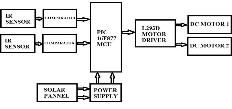
Fig 2- block diagram
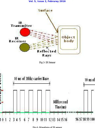
Fig 3- IR Sensor
Fig 4 -Waveform of IR sensor
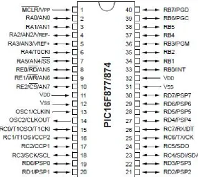
PIC16F877AMICROCONTROLLER
Fig 5- PIC16F877A Microcontroller pin diagram
Features:
High performance RISC CPU
Only 35 single word instructions to learn
All single cycle instructions except for program branches which are two cycle
Operating speed: DC - 20 MHz clock input DC - 200 ns instruction cycle
Up to 8K x 14 words of FLASH Program Memory, Up to 368 x 8 bytes of Data Memory (RAM) Up to 256 x 8 bytes of EEPROM Data Memory
Interrupt capability (up to 14 sources)
Direct, indirect and relative addressing modes
Power-on Reset (POR)
Power-up Timer (PWRT) and Oscillator Start-up Timer (OST)
Watchdog Timer (WDT) with its own on-chip RC oscillator for reliable operation
Programmable code protection
Power saving SLEEP mode
Fully static design
In-Circuit Serial Programming(ICSP) via two pins
Single 5V In-Circuit Serial Programming capability
In-Circuit Debugging via two pins
Processor read/write access to program memory
Wide operating voltage range: 2.0V to.5V
High Sink/Source Current: 2525 MA
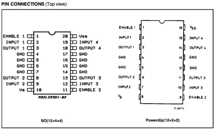
III.MOTORDRIVEL293D
Fig 6- Motor Driver Pin diagram
The L293D integrated high voltage, high current 4 channel driver device. Use to receive standard DTL or TTL logic levels and to rotate inductive loads (such as relays solenoids , DC and stepping motors) and switching power transistors To Elaborately use as two bridges each pair of channels is equipped with an enable input.
A provided apart supply for the logic, due to the operation at a lower voltage and internal diodes are add. This device is suitable for use in switch applications at frequencies up to 5 kHz. The L293D is agglomerate in a 16 lead plastic package which has 4 centre pins connected jointly and used for heat sinking The L293D is agglomerate in a 20 lead surface mount which has 8 centre pins connected jointly and used for heat sinking.
Working of L293D:
L293D Logic Table:
Now consider a Motor output pins connected on left side (pin 3,6). For rotating the motor in clockwise direction the input pins provided with Logic 1 and Logic 0.
Logic table motor drive
Pin Logic & Pin Logic Direction of Rotation of Motor
Pin 2 Logic1 & Pin 7 Logic 0 Clockwise Direction
Pin 2 Logic 0 & Pin 7 Logic 1 Anticlockwise Direction
Pin 2 Logic 1 & Pin 7 Logic 0 No Rotation
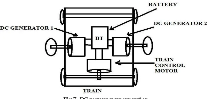
IV.POWERGENERATION
Fig 7- DC motor power generation
The electrical power generation system is used to generate electrical power with the help of movement of train. This method provides electrical power by using railway road track and DC generator. In this method mechanical energy converted into electrical energy. This energy is renewable energy, we know that train needs more amount of power to accelerate the power required is more and this power generation is more costly. Due to this in our project used new method to generate power. In this circuit some electrical device such as to DC generator, battery storage, train control motor. In our circuit DC generator is mounted on the base of railway bogies on both side and shaft of this DC generator through outside. And it moves track of train proportional to the movement of train. Due to moving of pulley, shaft of DC generator also rotated. And electrical power is generate, this power stored in battery and this power to accelerate the train
V. FEATUREOFPROPOSEDSYSTEM:
1) The system will consist of 2IR trans-receiver pairs.
4) Bidirectional gate controlling or Bidirectional train sensing.
5) The gate will be closed till the whole train passes out.
6) The opening of gate will be sensor based on delay based.
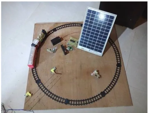
VI.EXPERIMENTAL RESULTS
In our project automatic railway gate control to avoid the several accident we have to use latest technology that is automatic railway gate control to avoid maximum number of accident on railway crossing
Now a day’s automatic system used in each and every sector. Therefore, system is more reliable, accurate and less time consume.
Fig 8.Model hardware implimentation Of automatic railway gate controller.
VII.CONCLUSION
We have designed in our project automatic railway gate control system. Small improvement in it. Automatic railway gate control system is more sensitive and also reduces railway accident to provide more secure life for road users. This system provides very large benefit for road user and railway management. Our system is completely automatic is suitable in rare area and also forest area at that place no station master is available it reduce railway accident. Second concept of our project to generate renewable energy using DC generator shaft is moving on railway track.
REFERENCES
1. International Journal of Engineering Research & Technology (IJERT) Vol.1 Issue 3,May 2012 ISSN: 22780181 2. International Journal of Modern Engineering Research (IJMER) Vol.2, Issue.1, Jan
3. Feb 2012 pp458 463 International Journal of Science, Engineering and Technology Research (IJSETR), Volume 3, Issue 5, May 2014 1551 ISSN: 2278 779
4. Siti Zaharah, “Transit District Advance Automated Train Detector System Case Study Description”, pp: 115 135.
6. Krishna, ShashiYadav and Nidhi, “Automatic Railway Gate Control Using Microcontroller”, Oriental Journal Of Computer Science &Technology, Vol.6, No.4, December 2013.
7. J. Banuchandar, V. Kaliraj, P. Balasubramanian, S. Deepa, N. Thamilarasi,“ Automated Unmanned Railway Level Crossing System”, in International Journal of Modern Engineering Research (IJMER)
8. Ahmed Salih Mahdi. Al-Zuhairi,“Automatic Railway Gate and Crossing Control based Sensors &Microcontroller ”, IN International Journal of Computer T rends and Technology (IJCTT) –Volume 4 Issue 7–July 2013.
9. Fundamental of embedded software by Daniel W Lewis
10. Fred coleman III, Young J.Moon (2011) Trapped vehicle detection system for four quadrant gates in high speed railway corridors, transportation research record 1648.