THE RESPONSE ANALYSIS OF SPACE VECTOR
PWM CONTROL BASED INDUCTION MOTOR
DRIVE
Sandeep Kumar Singh
1, Amit Patel
2,
Kamal Singh
3, Mohit pandey
4Department of Electrical Engineering
1,2
Bhagwant Institute of Technology, Muzaffarnagar-251315, (India)
3
Radha Govind Engineering College, Meerut -250004, (India)
4
ACME College of Engineering Ghaziabad-210206, (India)
ABSTRACT
Pulse Width Modulation variable speed drives are increasingly applied in many new industrial applications that
require superior performance. In this paper three-phase voltage source inverter which is based on vector
control with power IGBTs is described. In ac motor drives, Space vector PWM inverters make it possible to
control both frequency and magnitude of the voltage and current applied to a motor. The simulation and
analysis of vector control based Induction motor is carried out. A voltage source inverter is commonly used to
supply a three-phase induction motor with variable frequency and variable voltage for variable speed
applications. In this paper first a model for Space vector PWM is made and simulated using MATLAB software
and its performance is analyzed. The simulation study reveals that Space vector PWM utilizes the voltage more
effectively.
Keywords:
3-Ф Induction Motor, Space Vector Pulse Width Modulation Technique, Voltage
Source Inverter.
I INTRODUCTION
The induction machine is used in wide variety of applications as a means of converting electric power to
mechanical power. Pump steel mill, hoist drives, household applications are few applications of induction machines. Induction motors are most commonly used as they offer better performance than other ac motors. The
three-phase induction motors are the most widely used electric motors in industry. They run at essentially
constant speed from no-load to full-load. We usually prefer dc motors when large speed variations are required.
Nevertheless, the 3-phase induction motors are simple, rugged, low-priced, easy to maintain and can be
manufactured with characteristics to suit most industrial requirements. An IM drive employing V/F method with
application of Space Vector Pulse Width Modulation (SVPWM) is better to understand. By using 3-level
inverter, ripples in speed and torque will reduce. The reference voltage vector is then realized using a voltage
vector modulator.[1] The comparative performances of three phase induction motors using space vector pulse
SVPWM can improve the quality of the stator current and reduce the torque ripple while maintaining the other performance characteristics of the system.[2] The control of IM number of Pulse width modulation (PWM)
schemes are used to for variable voltage and frequency supply and main objective of this paper is analysis of
Induction motor with SVPWM fed inverter and harmonic analysis of voltages & current. There is an increasing
trend of using space vector PWM (SVPWM) because of it reduces harmonic content in voltage, Increase
fundamental output voltage by 15% & smooth control of IM.[3] Voltage source inverter type SVPWM based
speed control of an induction motor using a fuzzy PI controller enables us to adjust the speed of the motor by
controlling the frequency and amplitude of the stator voltage; the ratio of the stator voltage to the frequency
should be kept constant. A space vector PWM technique is also developed based on the vector space
decomposition. The techniques developed in this paper can be generalized for the control of an induction machine with an arbitrary number of phases.[4-6] In space vector PWM method for a three-level inverter fed
induction motor drive, a number of Pulse Width Modulation (PWM) schemes are used to obtain variable voltage
and frequency supply from an inverter. There is an increasing trend of using SVPWM because of their easier
digital realization and better dc bus utilization.[7]
II PRINCIPLE OF OPERATION
SVPWM technique was originally developed as a vector approach to pulse width modulation for three-phase
inverters. The SVPWM method is frequently used in vector controlled applications. In vector controlled
applications this technique is used for reference voltage generation when current control is exercised. It is a
more sophisticated, advanced, computation intensive technique for generating sine wave that provides a higher
voltage with lower total harmonic distortion and is possibly the best among all the pulse width modulation
techniques. It confines space vectors to be applied according to the region where the output voltage vector is
located. Because of its superior performance characteristics, it is been finding wide spread applications in recent
years. The main aim of any modulation technique is to obtain variable output voltage having a maximum fundamental component with minimum harmonics. Many PWM techniques have been developed for letting the
inverters to posses various desired output characteristics to achieve the wide linear modulation range, less
switching losses, lower harmonic distortion.
Vdc
a
a’
b
c
b’
c’
S1
S4
S6
S2
S5
S3
V
bV
aV
c+
-
Vab Vca NVbc
Load
C
The SVPWM technique is more popular than conventional technique because of more efficient use of DC supply voltage, 15% more output voltage then conventional modulation, lower Total Harmonic Distortion
(THD) and prevent un-necessary switching hence less commutation losses. Firstly model of a three-phase
inverter is presented on the basis of space vector representation. The three-phase VSI is reproduced in Fig.1.
There are six power switches that shape the output, which are controlled by the switching variables and
therefore, the on and off states of the upper switches can be used to determine the output voltage.
SVPWM refers to a special switching sequence of the upper power switches of a three-phase power inverter. It
has been shown to generate less harmonic distortion in the output voltages and/or currents applied to the phases
of a power system and to provide more efficient use of supply voltage compared with other modulation
technique. To implement SVPWM, the voltage equations in the abc reference frame can be transformed into the
stationary reference frame that consists of the horizontal (d) and vertical (q) axes as depicted in fig. 2.
Fig.2 The Relationship of a-b-c Reference Frame And Stationary d-q Reference Frame
III SIMULATION RESULTS
Variable voltage and frequency supply to ac drives is invariably obtained from a three-phase voltage source
inverter. Here is used three-phase voltage source inverter which is carrier-based sinusoidal PWM (Sinusoidal
PWM) with power IGBTs is described. In ac motor drives, SPWM inverters make it possible to control both frequency and magnitude of the voltage and current applied to a motor. The simulation results before and after
speed change are shown and various outputs are obtained like as rotor current waveform, rotor speed waveform,
electromagnetic torque waveform. The Simulink Model of Vector control based Induction motor drive is shown
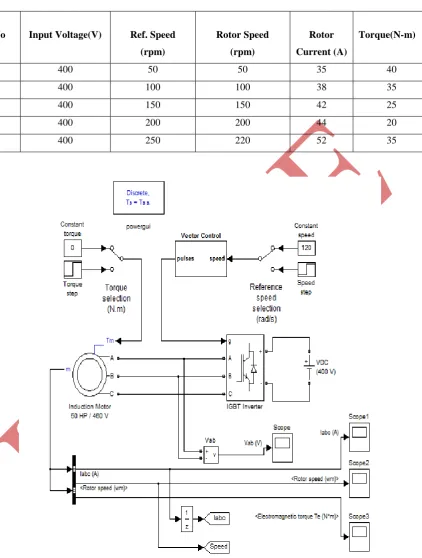
in fig. 4. This model is simulated for the different speeds from 50 rpm to 250 rpm at the input voltage of 400V
and the different responses of rotor current; rotor speed and electromagnetic torque are obtained which are
shown in figures from fig. 4 to fig. 17. The different values of the parameters are shown in table 1.
q Axis
d axis
a
b
Table 1: The Response Analysis of Rotor Current, Rotor Speed and Electromagnetic Torque
Fig.3 Simulink Model of Vector control based Induction motor
S.No Input Voltage(V) Ref. Speed
(rpm)
Rotor Speed
(rpm)
Rotor
Current (A)
Torque(N-m)
1 400 50 50 35 40
2 400 100 100 38 35
3 400 150 150 42 25
4 400 200 200 44 20
Fig.4 Rotor speed waveform at 50 rpm reference speed Fig.5 Rotor current waveform at 50 rpm reference
speed
Fig.6 Rotor torque waveform at 50 rpm reference speed Fig.7 Rotor speed waveform at 100 rpm reference speed
Fig.8 Rotor current waveform at 100 rpm reference speed Fig.9 Rotor torque waveform at 100 rpm reference speed
Fig.12 Rotor torque waveform at 150 rpm reference speed Fig.13 Rotor speed waveform at 200 rpm reference speed
Fig.14 Rotor current waveform at 200 rpm reference speed Fig.15 Rotor torque waveform at 200 rpm reference
speed
Fig.16 Rotor speed waveform at 250 rpm reference speed Fig.17 Rotor current waveform at 250 rpm reference speed
Fig.18 Rotor torque waveform at 250 rpm reference speed
IV CONCLUSIONS
The Space vector based induction motor drive is analyzed and designed with MATLAB simulink model which
The different speeds from 50 rpm to 250 rpm at the input voltage of 400V and the different responses of rotor current, rotor speed and electromagnetic torque are obtained. The simulation study reveals that Space vector
PWM utilizes the voltage more effectively.
REFERENCES
[1] Srinivasa Rao Maturu and Avinash Vujji," SVPWM Based Speed Control of Induction Motor Drive with
Using V/F Control Based 3-Level Inverter" VSRD-IJEECE, Vol. 2 (7), 2012, 421-437.
[2] Fizatul Ainipatakar, Marizan sulaiman and Zulkifilieibrahim," Comparison Performance Of Induction
Motor Using Svpwm And Hysteresis Current Controller"" Jatit & Lls, Vol. 30 No.1, 1992-8645.
[3] Mr. Sandeep N Panchal, Mr. Vishal S Sheth, Mr. Akshay A Pandya," Simulation Analysis of SVPWM
Inverter Fed Induction Motor Drives", International Journal of Emerging Trends in Electrical and
Electronics (IJETEE) Vol. 2, Issue. 4, April-2013.
[4] R. Arulmozhiyaly and K. Baskaran," Implementation of a Fuzzy PI Controller for Speed Control of
Induction Motors Using FPGA,Journal of Power Electronics, Vol. 10, No. 1, January 2010.
[5] R. Arulmozhiyal," Space Vector Pulse Width Modulation Based Speed Control of Induction Motor using
Fuzzy PI Controller,"International Journal of Computer and Electrical Engineering, Vol. 1, No.
1,1793-8198.
[6] Yifan Zhao, Student Member, and Thomas A. Lipo, Fellow, "Space Vector PWM Control of Dual
Three-Phase Induction Machine using Vector Space Decomposition," IEEE Transactions On Industry
Applications, Vol. 31, No.5, 0093-9994/95.
[7] M. SajediHir, Y. Hoseynpoor, P. MosadeghArdabili, T. PirzadehAshraf," Modeling and Simulation of