78: 5–8 (2016) 101–107 | www.jurnalteknologi.utm.my | eISSN 2180–3722 |
Jurnal
Teknologi
Full Paper
SOLAR
-
POWERED ADSORPTION REFRIGERATION CYCLE
OPTIMIZATION
Norhafizah Ahmad Junaidi*, Tohru Suwa
TAKASAGO Thermal/Environmental Systems Laboratory
Malaysia-Japan International Institute of Technology (MJIIT)
Universiti Teknologi Malaysia, Kuala Lumpur, Malaysia
Article history
Received
19 September 2015
Received in revised form
17 December 2015
Accepted
16 January 2016
*Corresponding author
[email protected]
Graphical Abstract
Abstract
Solar energy is an attractive energy source among various renewable energy resources in Malaysia as relatively high solar radiation is available throughout the year. This solar energy can be utilized for air-conditioning by using solar-powered adsorption refrigeration cycle. Intermittent nature of the solar radiation leads to a challenge for continuous air-conditioning operation. In the present study, a combination of solar-powered adsorption refrigeration system and thermal storage is studied. Activated carbon-ammonia and activated carbon-methanol are the working pairs of the adsorption reaction. Analytical calculation results show that activated carbon-methanol pair indicates higher coefficient of performance (COP) than activated carbon-ammonia pair, while adsorption chiller system with hot water thermal storage has higher COP than the system with ice thermal storage. For the activated carbon-methanol case with hot water thermal storage, the COP is 0.79. Since this COP analysis is based on the ideal case with uniform temperature distribution within the reactor beds, which achieves equilibrium states at the end of the reactions. In more realistic situation, the reaction process will be terminated before reaching to the equilibrium states because of the non-uniform temperature distribution and the time required for the reaction. Transient simulation in which heat transfer and reaction equation are combined will be performed to model actual reactors.
Keywords: Solar-powered; adsorption refrigeration; adsorption capacity; thermal
storage
© 2016 Penerbit UTM Press. All rights reserved
1.0 INTRODUCTION
The development of solar refrigeration technologies became the worldwide interest because the air-conditioning demand increases in parallel with the availability of the solar radiation [1]. Solid adsorption refrigeration system is a green technology to reduce the dependency on electricity from fossil fuels and producing cooling for air-conditioning from solar energy. Solid adsorption refrigeration is achieved by adsorbing gaseous refrigerant onto the porous surface of solid adsorbent. When solar energy is used as the main energy source, activated carbon, zeolite, and silica gel are the common materials used as an adsorbent. Environmental-friendly materials including ammonia, methanol, or water can be a refrigerant. The adsorbent-refrigerant pairs that employ these materials are considered as zero ozone
depletion potential as well as zero global warming potential.
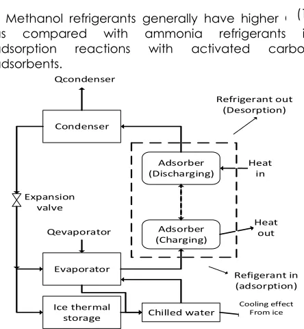
The solar adsorption refrigeration system consists of a solar collector, adsorber reactors, a condenser, and an evaporator. The adsorption refrigeration cycle is shown in Figure 1. When solar radiation is available, the solar collector captures the solar thermal energy, which is transferred to an adsorber reactor. The heated adsorber reactor releases the refrigerant from its adsorbent in desorption process. The released refrigerant is liquefied in the condenser and sent to the evaporator. At the same time, heat is removed from another adsorber reactor, which adsorbs the refrigerant vapor from the evaporator. As the pressure in the charging adsorber reactor reduces, the refrigerant vaporizes in the evaporator. As a result, heat is removed from the air-conditioning working fluid at the evaporator. These desorption
Condenser
Evaporator
Adsorber (Discharging)
Adsorber (Charging) Expansion
valve
Refigerant in (adsorption)
Heat in
Heat out Qcondenser
Qevaporator
Refrigerant out (Desorption)
Ice thermal
storage Chilled water
XX:1 (2015) 1–6 | www.jurnalteknologi.utm.my | eISSN 2180–3722 |
and adsorption processes are performed alternately between the two adsorber reactors.
The solar adsorption refrigeration processes show low coefficient of performance (COP) and low specific cooling effect (SCE). These drawbacks are caused by the thermal inertia of the adsorbent beds, and can be improved by enhancing the heat and mass transfer in the adsorbent beds [2]. Solar radiation is available intermittently during the daytime due to the humidity in the air, while solar radiation is not available during the night. Some form of thermal storage has to be introduced to provide air-conditioning even when solar radiation is low or not available. The COP of the adsorption refrigeration system is calculated by dividing the cooling capacity gained by the heating capacity required to heat the adsorbent reactors as in Eqn.(1).
Methanol refrigerants generally have higher COP as compared with ammonia refrigerants in adsorption reactions with activated carbon adsorbents.
Figure 1 Solar adsorption refrigeration system
Many studies on adsorption refrigeration have been focused on mathematical modeling of heat and mass transfer in the adsorbent beds. The major concerns were on adsorption working pairs’ reaction performances, heat transfer in adsorbent beds, and the coupled heat and mass transfer processes. The modeling techniques of heat and mass transfer process of a local thermal equilibrium among the adsorbent and refrigerants in uniform and non-uniform temperature-based models have been reported [3-4]. Recently, continuous operations of cooling production by solar adsorption refrigeration were simulated and the results were validated with thermodynamic analysis [1, 5]. Hassan also suggested a new adsorption refrigeration system concept, in
which adsorption process occurs at a constant temperature, achieved at a minimum pressure. The minimum pressure for adsorption process is introduced as the adsorption pressure and this pressure is lower than the evaporator pressure [1]. However, additional methods are required to prove the practicality to achieve this theoretical minimum pressure for adsorption, which is set at lower than evaporator pressure as in ideal adsorption refrigeration cycle. Furthermore, finned-tube adsorber reactors design was optimized and the mass transfer of the whole system was simulated [6-8]. Experimental results on the performance of the working pairs of adsorbent refrigerants were reported [9-10]. The results were used to study the adsorption capacity and adsorption kinetics of the working pairs for solar-powered cooling.
The motivation of this research is to study the transient effects on the reaction rate, and temperature and pressure distribution inside the adsorbent bed. The studies on such transient analysis are very limited. The transient process in the literature proved that the pressure distribution inside the adsorbent beds is uniform during adsorption and desorption processes [11-12]. However, the temperature in the adsorbent beds is not uniform and the uneven temperature distribution degrades the reaction rate of adsorption and desorption processes.
In this paper, activated carbon-ammonia and activated carbon-methanol adsorbent-refrigerant working pairs are used to study the time-dependent adsorption and desorption reactions in adsorbers to provide cooling continuously for thermal comfort in buildings. To enhance the performance of the solar-powered adsorption refrigeration system, a methodology to optimize the solar-powered adsorber reactor design is developed taking its transient performance into account. Simulation of time-dependent reaction in the adsorption reactors of the adsorption system is investigated to study the temperature distribution inside the adsorbent bed and its effect on the reaction rate. In Malaysia, sunlight is available twelve hours a day on average. The solar energy from the sunlight will be used as thermal energy supply for the adsorption refrigeration system.
2.0 SOLAR ADSORPTION REFRIGERATION
AND THERMAL STORAGE
2.1 Adsorption Capacity Of Reaction Working Pairs
A good adsorbent has a large adsorption capacity and strong affinity for refrigerant with wide operating temperature and pressure ranges [15]. Meanwhile, a should have high latent heat of vaporization to increase refrigerant adsorption capacity. The suitable refrigerants for solar adsorption refrigeration system
Condenser
Evaporator
Adsorber (Discharging)
Adsorber (Charging) Expansion
valve
Refigerant in (adsorption)
Heat in
Heat out Qcondenser
Qevaporator
Refrigerant out (Desorption)
Ice thermal
storage Chilled water
Cooling effect From ice
XX:1 (2015) 1–6 | www.jurnalteknologi.utm.my | eISSN 2180–3722 |
are including water, ammonia and methanol. Water refrigerant is limited for air-conditioning applications, since it cannot operate in subzero temperatures. In this study, the adsorption capacity of activated carbon adsorbent with ammonia or methanol refrigerants is determined analytically. The adsorption capacity of ammonia and methanol refrigerants at their saturated pressure and system temperature are calculated from adsorption isotherm equation with the conditions listed in Table 1 and the results are plotted in Figure 2, and this data will be compared with the experimental results. Eqn.(2) is the adsorption isotherm equation [2]:
Table 1. Variables for D-A equation [1]
Refrigerant Xmax (g/g) K n
Methanol 0.356 32.65 2 Ammonia 0.29 3.1853 1.0957
Carbon pellets: Type 208C
Figure 2 Calculated adsorption capacity of ammonia and
methanol for hot water thermal storage
From the adsorption capacity shown in Figure 2, methanol refrigerant shows higher adsorption capacity compared to ammonia refrigerant. Ammonia refrigerant operates at pressure higher than the atmospheric pressure, which is between 0.5 bars to 5 bars, while methanol refrigerant operates at pressure lower than atmospheric pressure. Too low operating pressure of refrigerant may draw outside air into the system and degrade its performance. For long term usage, ammonia may corrode the surface of the reactor while methanol refrigerant is not corrosive.
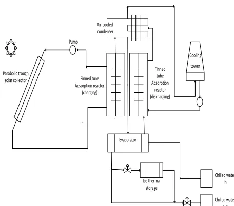
2.2 Solar Collector And Thermal Storage For Continuous Operations Of Chillers
Flat plate solar collectors were used in most of the previous work for solar adsorption, while parabolic
trough collectors (PTC) were rarely used. A standard flat plate solar collector provides thermal energy at temperatures between 60oC to 80oC, while PTC can
provide solar thermal energy up to 350oC.
In this study, solar energy is utilized as the heat source for the adsorption refrigeration system. In order to provide cooling when solar radiation is not available, thermal storage is used with the solar adsorption chillers. There are three possible configurations of thermal storage integrated into the adsorption refrigeration systems; hot water thermal storage, increased capacity of adsorbent beds, and ice thermal storage.
In the first case, hot water is used to store heat energy in the form of sensible heat. When solar radiation more than the adsorption reactors require is available, the excess thermal energy is stored in the form of hot water in a tank. The hot water thermal storage extends the operation hours of the adsorption reactors. This configuration is a combination of the existing technologies: waste heat-operated adsorption chiller and the hot water thermal storage. Further technology development is not needed in terms of refrigeration system configuration.
Figure 3 Adsorption chillers with hot water thermal storage
Figure 3 shows the adsorption chiller system with hot water thermal storage. Although the boiling temperature of water is 100oC, the water
temperature to store is limited to 85oC. This is because
the highest operating temperature for water pumps is 85oC to avoid cavitations. As a result, the desorption
temperature of the discharging adsorber reactor is lower than 85oC. The lower the temperature for
desorption, the less the amount of refrigerant that flows out of the adsorbent bed, which leads to lower COP of the refrigeration cycle. For hot water thermal storage, the evaporator temperature for the present system is set to 5oC considering the demand side
temperature requirement for air-conditioning.
Hot water thermal storage
Pump
Finned tube Adsorption
reactor (charging)
Chilled water in Parabolic
trough solar collector
Evaporator Air-cooled
condenser
Cooling tower
P-77
Chilled water out Finned
tube Adsorption
reactor (charging)
XX:1 (2015) 1–6 | www.jurnalteknologi.utm.my | eISSN 2180–3722 |
For the second case, adsorption beds with extended capacity are used as thermal storage as shown in Figure 4. Transient analysis and performance prediction studies were reported for three adsorber beds, in which cold energy is stored in the form of refrigerant in a separate refrigerant storage tank at ambient temperature within one large bed, and the other two beds perform adsorption and desorption alternately [3]. This approach makes the configuration and operation of the adsorption cycle complex. The commercially available adsorption chiller units cannot be used as they are.
Figure 4 Adsorption chillers with extended capacity
adsorber beds
Figure 5 Adsorption chillers with ice production thermal
storage
In the third case, ice thermal storage is integrated into the adsorption refrigeration system as shown in Figure 5. During the daytime, ice is created using the excessive solar thermal energy. Whenever solar energy is unavailable, the thermal energy stored in the ice can be utilized to respond to the air-conditioning demand. Ice thermal storage allows solar radiation fluctuations that do not agree with the
thermal energy for air-conditioning demand. The volume of the ice thermal storage is smaller than other forms of thermal storage because of the large latent heat of fusion of water. For ice thermal storage, the evaporator temperature for the studied system is set to -15oC. The discharging capacity for
the adsorption reactors must be large enough to provide cooling for air-conditioning and ice generation continuously. At the same time, the heat provided to the discharging adsorption reactor fluctuates due to the intermittency of solar radiation. The transient heat transfer and the resulting desorption reaction within the reactor influences its performance.
In Figure 6, a comparison of adsorption capacity calculated from Equation (2) and the material properties in Table 1, for ammonia and methanol refrigerants towards carbon adsorbents.
Figure 6 Adsorption capacity for system with ice thermal
storage
Table 2 COP of the studied system using hot water and ice
thermal storage
Reaction working
pairs Hot water thermal COP of the system storage Ice thermal storage Activated
carbon-ammonia 0.72 0.66 Activated
carbon-methanol 0.79 0.74
From Figure 6, the desorption temperature of hot water thermal storage case is up to 85oC, while it is
100oC for ice thermal storage case. A performance
comparison of the refrigeration system using hot water and ice thermal storages are shown in Table 2. In the COP calculation, the mass of adsorbent used is 10 kg, the mass flow rate of ammonia refrigerant is 1.495 kg/s, while the mass flow rate of methanol refrigerants is 3.045 kg/s.
From the COP calculations, it is shown that activated carbon-methanol working pair shows
Pump
Evaporator Air-cooled condenser
Cooling tower Parabolic
trough solar collector
Extra reactor For thermal storage Finned
tube adsorber reactor (discharging) Finned-tube
Adsorber reactor
(charging)
Chilled water in
Chilled water out
P-211
Pump
E-10 Finned tune Adsorption reactor
(charging)
Finned tube Adsorption
reactor (discharging)
Evaporator Air-cooled condenser
Cooling
tower
Ice thermal storage Parabolic trough
solar collector
Chilled water in
XX:1 (2015) 1–6 | www.jurnalteknologi.utm.my | eISSN 2180–3722 |
higher COP for both hot water and ice thermal storage cases compared to activated carbon-ammonia. The adsorption refrigeration system with hot water thermal storage has higher COP than that of ice thermal storage case for both of the reaction pairs. For the ice thermal storage case, the higher discharging adsorber reactor temperature leads to higher COP. Still, the lower evaporator temperature causes lower COP. Combining these two effects the ice thermal storage case has lower COP than the hot water thermal storage case. This calculation is made in ideal conditions assuming uniform temperature distribution within the adsorbers.
According to the analytical calculation results shown in Table 2, the solar-powered adsorption refrigeration cycle with hot water thermal storage with activated carbon-methanol working pair case has the highest COP. Although the volume is larger than ice thermal storage, hot water thermal storage is less expensive and easier to design. Since silica gel-water adsorption pair, which operates with negative pressure, is frequently used for the conventional adsorption chillers, the existing technology can be used for the activated carbon-methanol pair, which also operates with negative pressure.
Due to the intermittent nature of solar radiation, it is not practical to design the refrigeration system that is able to respond to all of the air-conditioning demands only by solar thermal energy all year around even if thermal storage is integrated into the refrigeration system. A backup heat source is required for stable operation. As the backup heat source, a boiler may be used to supply heat energy to the adsorbers.
2.3 Adsorber Reactor
From left: Figure 7(a) Adsorber model in charging mode,
Figure 7(b) Adsorber model in discharging mode
Figure 7(a) and (b) show the adsorber reactor model in charging and discharging modes for the future prototype test. In the refrigeration system, two identical adsorber reactors are used to perform adsorption and desorption alternately for air-conditioning.
The adsorber reactors are cylindrical and built vertically. Heat transfer fluid will flow into and from the adsorber inside the heat transfer tube. Perforated plates are placed at the top and bottom of the
adsorbent beds to allow the refrigerant vapor to flow into and out from the adsorbent beds. Fins are built along the length of the cylinder outside of the inner tube to enhance the heat transfer within the adsorber reactors. The adsorber dimensions and fin configuration will be identified from the simulation results.
The distribution of pressure is almost uniform within the beds [10], while the temperature distribution within the adsorbent beds is not uniform. The rate of reaction will be simulated using finite element analysis software. The performance of the reactors can be improved by enhancing the heat transfer within the adsorbent beds by introducing fins.
3.0 EXPERIMENT AND SIMULATION
3.1 Adsorption Capacity Experiment
Figure 8 Reaction calorimetry experimental set up.
The adsorption performance of selected adsorbent-refrigerant working pairs is important to the performance of solar adsorption refrigeration systems. As a future work, the adsorption capacity experiment is planned using a reaction calorimeter as shown in Figure 8.
The operating parameters of ammonia refrigerant is as follow; evaporating pressure, Pe = 5.339bars at
evaporating temperature, Te = 5oC, and condensing
pressure, Pc = 15.0bars at condensing temperature, Tc
= 35oC. Meanwhile, the operating parameters of
methanol; the evaporating pressure, Pe = 0.4bars at
evaporating temperature, Te = 5oC, and condensing
pressure, Pc = 1.3bars at condensing temperature, Tc
= 35oC. The total surface area, the apparent density,
and the average particle size of the granular activated carbon are to be measured. The reactor is always kept at predetermined temperature throughout the experiment. The heat of adsorption reaction is obtained from the latent heat of vaporization of the respective refrigerants. The reaction calorimetry experiment is designed from the experimental procedure in [14] by using ammonia and methanol as refrigerants.
Reaction calorimeter
Electronic mass balance Water tank
(circulator)
Flowmeter
Refrigerant tank
Control unit & PC
XX:1 (2015) 1–6 | www.jurnalteknologi.utm.my | eISSN 2180–3722 |
The measured adsorption capacity, Xexp is calculated as mass of adsorbent after adsorption process divided by the initial mass of adsorbent, m1 as in Eqn.(3):
The measured results, Xexp will be used for adsorption reactor simulation.
3.2 Simulation of Adsorber Model
The analytical solution shown in Table 2 is based on ideal cases where reactions in equilibrium are achieved at the ends of adsorption and desorption processes with uniform temperature distributions. In more realistic situations, it is hard to achieve the uniform temperature distribution within time. As a result, the reactions are terminated before they reach equilibrium state. Since the reaction rate is a function of reaction temperature as expressed in Eqn. (2), heat transfer within the reactors plays an important role to enhance the reaction. In addition, the reactions are time dependent. The charging reaction occurs from discharged state to charged state, while discharging reaction proceeds in the opposite direction.
The transient reaction within the adsorber reactors will be simulated using finite element method. Heat transfer and reaction rate relation in Eqn. (2) are combined in the simulation model. The dependent variables will be temperature distribution within the bed, pressure of the refrigerant and amount of refrigerant adsorbed by the adsorbent. To enhance the heat transfer within the adsorber for faster reaction, radial circular fin will be designed in the adsorbent bed.
4.0 CONCLUSION
The reaction rate and COP for activated carbon-ammonia and activated carbon-methanol reaction pairs used for solar-powered adsorption refrigeration system is studied. Activated carbon-methanol reaction pair showed higher COP than activated carbon-ammonia pair, while an adsorption refrigeration system with hot water thermal storage has higher COP than the system with ice thermal storage. As a future work, simulation with heat transfer and reaction capabilities is planned.
Acknowledgement
The authors would like to express their appreciation to Takasago Thermal Engineering Co. Ltd., Japan, for providing financial support for this work.
References
[1] Hassan, H. Z., Mohamad, a. a. and Al-Ansary, H. a. 2012. Development Of A Continuously Operating Solar-Driven Adsorption Cooling System: Thermodynamic Analysis And Parametric Study. Appl.
Therm. Eng. 48: 332–341.
[2] Deshmukh, H., Maiya, M. P. and Srinivasa Murthy, S. 2015. Continuous Vapour Adsorption Cooling System With Three Adsorber Beds. Appl. Therm. Eng. 82: 380– 389.
[3] Critoph, R. E. and Metcalf, S. J. 2004. Specific Cooling Power Intensification Limits In Ammonia-Carbon Adsorption Refrigeration Systems. Appl. Therm. Eng. 24 (5–6): 661–678.
[4] Tamainot-Telto, Z., Metcalf, S. J., Critoph, R. E., Zhong, Y. and Thorpe, R. 2009. Carbon-Ammonia Pairs For Adsorption Refrigeration Applications: Ice Making, Air Conditioning And Heat Pumping. Int. J. Refrig. 32(6): 1212–1229.
[5] Umair, M., Akisawa, A. and Ueda, Y. 2014. Simulation Study of Continuous Solar Adsorption Refrigeration System Driven by Compound Parabolic Concentrator. Open Renew. Energy J. 1–12.
[6] Louajari, M., Mimet, A. and Ouammi, A. 2011. Study Of The Effect Of Finned Tube Adsorber On The Performance Of Solar Driven Adsorption Cooling Machine Using Activated Carbon-Ammonia Pair.
Appl. Energy. 88(3): 690–698.
[7] Wang, L. W., Wu, J. Y., Wang, R. Z., Xu, Y. X., Wang, S. G. and Li, X. R. 2003. Study Of The Performance Of Activated Carbon-Methanol Adsorption Systems Concerning Heat And Mass Transfer. Appl. Therm. Eng. 23(13):1605–1617.
[8] Hassan, H. Z., Mohamad, a. and Bennacer, R. (2011). Simulation Of An Adsorption Solar Cooling System.
Energy. 36(1): 530–537.
[9] El-Sharkawy, I. I., Saha, B. B., Koyama, S., He, J. K., Ng, C. and Yap, C. 2008 Experimental Investigation On Activated Carbon-Ethanol Pair For Solar Powered Adsorption Cooling Applications. Int. J. Refrig. 31(8):1407–1413.
[10] Abu-Hamdeh, N., Alnefaie, H. K. a. and Almitani, K. H. 2013. Design And Performance Characteristics Of Solar Adsorption Refrigeration System Using Parabolic Trough Collector: Experimental And Statistical Optimization Technique. Energy Convers. Manag. 74: 162–170.
[11] Zhao, Y., E. Hu, and Blazewicz, A. 2012. Dynamic Modelling Of An Activated Carbon-Methanol Adsorption Refrigeration Tube With Considerations Of Interfacial Convection And Transient Pressure Process.
Appl. Energy. 95: 276–284.
[12] Anyanwu, E. E., Oteh, U. U. and Ogueke, N. V. 2001 Simulation Of A Solid Adsorption Solar Refrigerator Using Activated Carbon/Methanol Adsorbent/Refrigerant Pair. Energy Convers. Manag. 42(7): 899–915.
[13] Pongtornkulpanich, A. 2014. Dynamic Simulation of Solid Adsorption Solar Refrigerator System with AC / CH 3 OH as a Working Pair. Energy Power Eng. 459– 465.
[14] Deshmukh, H., Maiya, M. P. and Srinivasa Murthy, S. 2015. Continuous Vapour Adsorption Cooling System With Three Adsorber Beds, Appl. Therm. Eng. 82: 380– 389.
XX:1 (2015) 1–6 | www.jurnalteknologi.utm.my | eISSN 2180–3722 |
[15] Allouhi, T. Kousksou, a. Jamil, Rhafiki,T. El, Mourad,Y. and Y. Zeraouli. 2015. Optimal Working Pairs For Solar Adsorption Cooling Applications. Energy. 79:235–247.
![Table 1. Variables for D-A equation [1]](https://thumb-us.123doks.com/thumbv2/123dok_us/1335725.1166543/3.612.55.292.194.488/table-variables-d-a-equation.webp)