University of Windsor University of Windsor
Scholarship at UWindsor
Scholarship at UWindsor
Electronic Theses and Dissertations Theses, Dissertations, and Major Papers
4-14-2017
Reducing Complexity Increasing Scalability on X-Ray stress
Reducing Complexity Increasing Scalability on X-Ray stress
system
system
Hussein Wehbe
University of Windsor
Follow this and additional works at: https://scholar.uwindsor.ca/etd
Recommended Citation Recommended Citation
Wehbe, Hussein, "Reducing Complexity Increasing Scalability on X-Ray stress system" (2017). Electronic Theses and Dissertations. 5956.
https://scholar.uwindsor.ca/etd/5956
This online database contains the full-text of PhD dissertations and Masters’ theses of University of Windsor students from 1954 forward. These documents are made available for personal study and research purposes only, in accordance with the Canadian Copyright Act and the Creative Commons license—CC BY-NC-ND (Attribution, Non-Commercial, No Derivative Works). Under this license, works must always be attributed to the copyright holder (original author), cannot be used for any commercial purposes, and may not be altered. Any other use would require the permission of the copyright holder. Students may inquire about withdrawing their dissertation and/or thesis from this database. For additional inquiries, please contact the repository administrator via email
Reducing Complexity, Increasing
Scalability on X-Ray Stress System
by
Hussein Wehbe
A Thesis
Submitted to the Faculty of Graduate Studies
through the Department of
Electrical and Computer Engineering
in Partial Fulfillment of the Requirements for
the Degree of
Master of Applied Science
at the University of Windsor
Windsor, Ontario, Canada
Reducing Complexity, Increasing Scalability on X-Ray
Stress System
by
Hussein Wehbe
APPROVED BY:
S. Rehse
Department of PhysicsE. Abdel-Raheem
Department of Electrical and Computer Engineering
K. Tepe, Advisor
Department of Electrical and Computer Engineering
iii.
DECLARATION OF ORIGINALITY
I hereby certify that I am the sole author of this thesis and that no part of this thesis has been
published or submitted for publication.
I certify that, to the best of my knowledge, my thesis does not infringe upon anyone’s
copyright nor violate any proprietary rights and that any ideas, techniques, quotations, or any other
material from the work of other people included in my thesis, published or otherwise, are fully
acknowledged in accordance with the standard referencing practices. Furthermore, to the extent
that I have included copyrighted material that surpasses the bounds of fair dealing within the
meaning of the Canada Copyright Act, I certify that I have obtained a written permission from the
copyright owner(s) to include such material(s) in my thesis and have included copies of such
copyright clearances to my appendix.
I declare that this is a true copy of my thesis, including any final revisions, as approved by
my thesis committee and the Graduate Studies office, and that this thesis has not been submitted
iv
ABSTRACT
Programmable Logic Controllers (PLCs), traditionally used for process control and automation,
have certain limitations. Firstly, they operate by running the ladder logic in a scan cycle that has
three steps: inputs canning, program execution, outputs updating. This sequential execution affects
the response time of the PLC for critical events, as they will keep waiting until they are read in an
inputs scanning step. Secondly, PLCs are expensive, available only in standard configurations and
need to be mounted on special panels. Finally, using PLC adds to wiring complexity of the system
and reduces scalability. As a solution to these limitations, this thesis proposes using an MCU based
embedded control system with event driven software architecture. For the implementation, an
ATMEGA-2560 MCU is selected and used in X-Ray measurement system automation board. The
controller is designed and implemented for Proto Manufacturing iXRD stress measurement system
to replace the existing PLC-based system. All iXRD machine inputs are configured to generate
interrupts at Atmega microcontroller to ensure faster response times based on the priority of the
system events. The hardware and the firmware designs implemented in the thesis allow quick and
easy expansion of the system by adding new inputs or outputs with a minimal wiring and smaller
number of new components. The new design minimizes the system number of components,
v
DEDICATION TO
My Mother: A strong and gentle soul who taught me to trust in God, believe in hard work and
that so much could be done with so little.
My Father: For earning an honest living for us and for supporting and encouraging me to
believe in myself.
My Brother Youssef: For supporting and being always by my side throughout my entire life.
My Wife: For supporting and understanding when I had to work late nights, always by my
side throughout this year.
My Daughter Salwa and Nephew Hamoudy: Who because of them, I will continue to push
myself to be the best version of myself so that when they grow up they will have a role model
vi
ACKNOWLEDGEMENTS
vii
CONTENTS
DECLARATION OF ORIGINALITY ... iii
ABSTRACT ... iv
DEDICATION TO ... v
ACKNOWLEDGEMENTS ... vi
CONTENTS ... vii
LIST OF FIGURES ... xi
LIST OF TABLES ... xiii
LIST OF ABBREVIATIONS ... xiv
1. INTRODUCTION ... 1
1.1 Problem Statement ... 2
1.2 Thesis Contribution ... 2
1.3 Design and Implementation Requirements ... 3
1.4 Thesis Organization ... 4
2. RELATED WORK AND BACKGROUND... 5
viii
2.2 PLC in Process Automation ... 5
2.2.1 PLC Sequential Execution and Response Time ... 6
2.2.2 PLC Manufacturing Cost ... 8
2.2.3 System Complexity and Scalability with PLC ... 8
2.3 MCU based Embedded Controllers in Automation ... 9
2.4 Current System Description... 10
2.5 RS-485 Communication Protocol ... 13
2.6 ATMEL ATMEGA-2560 Microcontroller ... 15
2.7 ATMEGA-2560 Programming Interface... 16
2.8 Summary ... 17
3. Design and Implementation ... 18
3.1 Introduction ... 18
3.2 The Design and Implementation Methodology ... 18
3.2.1 Requirements Analysis ... 18
3.2.2 System Design ... 19
3.2.3 XSA Board Design ... 20
3.2.3.1 MCU Selection ... 21
3.2.3.2 Sensors Interface ... 21
Temperature sensor interface ... 21
ix
Photomicrosensor (EE SX1018) ... 23
DRV101:U9 – Solenoid driver ... 24
RC low-pass filter ... 26
Voltage Regulator ... 26
Temperature comparator ... 27
RS-485 Transceiver ... 28
XSA Board Schematic and PCB Layout ... 29
3.2.4 SW Design and Implementation ... 30
3.2.4.1 SW Architecture ... 31
Software Component Diagram ... 31
Software Behavioral Diagram ... 33
3.2.4.2 Application Layer ... 36
Main ... 36
Interrupt Service Routines ... 38
Timer0 compare ISR ... 38
INT2 ISR ... 40
INT0 ISR ... 40
USART0_UDRE_vect ... 41
USART0_RX_vect ... 43
x
LED/Switch handling functions ... 45
3.2.4.3 Middleware Layer ... 45
Timer Functions ... 46
Interrupt Setup functions ... 46
Serial Communication (USART) functions ... 46
SPI functions ... 46
Miscellaneous Controller Initialization Functions ... 47
3.3 Summary ... 47
4. RESULTS and CONCLUSION ... 48
4.1 Introduction ... 48
4.2 Response Time Analysis ... 48
4.3 System Complexity Analysis... 50
4.4 System Scalability Analysis ... 50
4.5 Cost Savings Analysis ... 51
4.6 Conclusion and Future work ... 52
REFERENCES: ... 54
APPENDIX ... 57
A. Interrupt Vectors in ATMEGA-2560 ... 57
xi
LIST OF FIGURES
Figure 1 - Sample ladder logic program ... 6
Figure 2 - Scanning the ladder program ... 7
Figure 3 - PLC execution cycle ... 8
Figure 4 - Existing iXRD X-Ray stress measurement system ... 10
Figure 5 - LEDEX Rotary Solenoid ... 11
Figure 6 - X-Ray stress measurement system architecture with PLC ... 13
Figure 7 - RS-485 configuration ... 14
Figure 8 - RS-485 data frame ... 15
Figure 9 - ATMEL-2560 pin diagram ... 16
Figure 10 - SPI interface ... 17
Figure 11 - X-Ray stress measurement system architecture with XSA board ... 20
Figure 12 - XSA block diagram ... 20
Figure 13: Temperature sensor interface circuit ... 22
Figure 14 - Comparator circuit ... 22
Figure 15 - Proximity Sensor ... 23
Figure 16 – Photomicrosensors circuit ... 24
xii
Figure 18 - RC-low pass filter ... 26
Figure 19 - Temperature comparator circuit ... 27
Figure 20 - MAX3491 Transceiver ... 29
Figure 21 - Hardware schematic and the PCB layout of XSA board ... 30
Figure 22 - Software component architecture ... 33
Figure 23 - Software behavioral architecture ... 34
Figure 24 - Control flow of main function ... 37
Figure 25 - Control flow of Timer0 interrupt ... 39
Figure 26 - Control flow - RS-485 transmit ISR ... 42
Figure 27 - Control flow - RS-485 receive ISR ... 44
xiii
LIST OF TABLES
Table 1 - Hardware Components on PCB ... 30
Table 2 - List of interrupts used in XSA board software ... 35
Table 3 - Response Times of XSA board and PLC ... 48
xiv
LIST OF ABBREVIATIONS
OEM Original Equipment Manufacturer PLC Programmable Logic Controller GM General Motors
LL Ladder Logic SoC System on Chip MCU Micro Controller Unit I/O Input / Output
PCB Printed Circuit Board
FPGA Field Programmable Grid Array SFC Sequential Function Chart PC Personal Computer
ADC Analog to Digital Converter PWM Pulse Width Modulation TTL Transistor-Transistor Logic RC Resistor Capacitor
LED Light Emitting Diode ISR Interrupt Service Routine SCI Serial Communication Interface DDR Data Direction Register
CPU Central Processing Unit DAC Digital to Analog Converter RTOS Real-Time Operating System
1
1.
INTRODUCTION
X-Ray, since its invention in 1895 [1], is used in many applications in medical and industrial applications, such as diagnosis of fractured bones, lung diseases, and baggage screening[2]. One of the important use cases of X-Ray diffraction technology is in the stress analysis of composite materials and the structural analysis of crystals [3].Companies like Proto Manufacturing in Windsor; and a few other companies around the globe, design and manufacture systems with X-Ray for residual stress mapping of composite materials, powder diffraction, and structural analysis of crystals [4]. However, an exposure to X-Rays and other radioactive materials associated with those systems are hazardous to the human health. For a safe and effective operation of these systems, automation to limit human interaction is essential [5]. That is why Original Equipment Manufacturers (OEMs) have been using Programmable Logic Controllers (PLCs) for the automation of the systems, which uses X-Rays.
PLC was first developed and used by General Motors (GM) in the 1970s[6][7] for the automation systems in their factories as a replacement of expensive and complex relay panels. Since then PLCs have evolved rapidly and have been de facto standard for controlling processes and automation. PLCs are popular because they are programmable, expandable, robust and secure. Invention of PLCs has also introduced a new way of programming where Ladder Diagram (LD), Functional Block Diagram (FBD), Structured Text (ST)[8] are used to enable engineers to implement process control and automation algorithms easily without any need to know underlying microcontroller and other hardware in PLCs.
2
In this thesis, a Microcontroller Unit (MCU) based control and automation system for X-Ray based stress measurement system will be investigated to replace a PLC based system to reduce the cost, complexity and increase response time. With this MCU based control and automation systems, the overall complexity and cost of Proto Manufacturing iXRD stress measurement system will be reduced. Then, the MCU based and PLC based system performances will be tested to verify the design objectives.
1.1
Problem Statement
PLCs, traditionally used for process control and automation, operate by continuously scanning sensor and control inputs, and apply control signals to actuators and relays. A PLC program continuously repeat this input scanning and apply control signaling multiple times per second, which is called a scan cycle of PLC. This cycle has three steps: inputs scanning, program execution, outputs updating[9].A convention is used in the PLC programming that it reads inputs from left to right and top to bottom order in LD and changes output states in the same order. Because of this flow pattern (i.e., left to right and top to bottom), inputs at the top of the rungs get higher priority than inputs on the lower rungs in a scan cycle. In successive cycles, reading and updating is periodic and is equal to the duration of the PLC scan cycle. This order is fixed and you cannot override it in the case of any critical event since an input in the lower rung needs to be serviced. That is why duration of a scan cycle of PLCs directly affects its response time even in a critical scenario[10].
1.2
Thesis Contribution
3
complexity of wiring and response time to an unanticipated event. An interrupt-driven MCU based automation system can respond to such unanticipated events and reduces problems associated with PLC scan cycle.
For the implementation, an ATMEGA-2560 [11] MCU is selected and used in X-Ray measurement system automation board. The controller is designed and implemented for Proto Manufacturing iXRD stress measurement system to replace the existing PLC-based system. All iXRD machine inputs are configured to generate interrupts at Atmega microcontroller to ensure faster response times based on the priority of the system events. The hardware and the firmware designs implemented in the thesis allow quick and easy expansion of the system by adding new inputs or outputs with a minimal wiring and smaller number of new components. A multi-node communication mechanism based on RS-485 is implemented between different communicating nodes of the existing system to maintain the functionality of the system intact but to have a shorter response time. The new design minimizes the system integration time and complexity, thereby reducing the overall system setup and maintenance costs.
1.3
Design and Implementation Requirements
An electronics control system board with a microcontroller, sensors and other hardware components shall be designed to automate the operation of Proto Manufacturing iXRD stress measurement system, which is currently automated using PLC. The new control system; without compromising the existing functionality, shall achieve the following objectives:
i. Improve the response time of the system by supporting priority based program execution vs. sequential execution of the PLC program.
ii. Reduce the system design cost by eliminating PLC and other non-critical elements in the system.
4
1.4
Thesis Organization
5
2.
RELATED WORK AND BACKGROUND
2.1
Introduction
This chapter will establish the necessary background needed for understanding the design and implementation of the MCU based board proposed and implemented in this thesis for the automation of X-Ray stress measurement system. With the developments in electronics and computer technology, microprocessors and microcontrollers have taken charge of process control and automation in all aspects of human life. Micro Controller Units (MCUs) also referred to as System on Chips (SoCs), are widely used in application specific control systems. An MCU is a single integrated circuit containing a processor core, memory and input/output peripherals and is suitable for implementing control applications with predefined set of tasks. In the field of process automation, MCU-based solutions are preferred by OEMs over other automation solutions such as PLCs. MCU based boards offer better performance, flexibility, customization and cost effectiveness over PLCs.
2.2
PLC in Process Automation
6
computer when specifications changed. The programs were written in high-level languages such as FORTRAN or low-level languages such as assembly, but the factory floor workers or technicians knew only ladder logic and it was not possible for them to learn new programming languages to reprogram computers. PLCs that use ladder logic programming were developed to overcome this limitation [13]. PLCs designed to provide ladder logic found wide acceptance in automation of large factory machines and processes. Over a period, PLCs also got into systems and machines where their usage was not really needed. For example, the X-Ray stress measurement system, referenced in this thesis does not need frequent changes in configurations and hence does not benefit from a PLC. In addition, because of their design, PLCs have an inherent limitation in the response time because of ladder logic and sequential execution discussed below. Other challenges faced by OEMs in using PLCs for automation are discussed in the following sections.
2.2.1 PLC Sequential Execution and Response Time
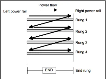
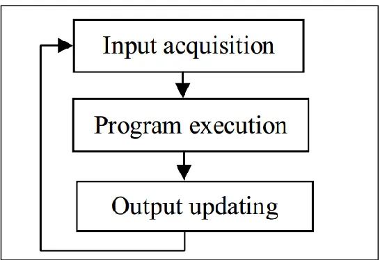
A typical ladder logic that PLC executes and its equivalent electrical circuit are as shown in Figure 1 [14]. The circuit is drawn in a horizontal line between two power lines L1 and L2, which resemble vertical sides of a ladder and the circuit itself looks like a rung in the ladder. Hence the name ladder logic coined for such systems. When a PLC is in a run mode, as shown in Figure 2, it scans the ladder logic from left to right and from top to bottom until it reaches an END rung and then resumes the execution at the top rung. This procedure of going through all the rungs of the program is called a PLC scan cycle. In each scan cycle, the PLC will firstly acquire all input values, secondly execute the program and then finally update outputs as shown in Figure 3.
7
Figure 2 - Scanning the ladder program
The disadvantage in this type of execution is that the PLC can only identify input changes that occurred before the start of its input scanning stage. That is why the response time for an input that changed immediately after the PLC completed reading that input is one scan cycle. One scan cycle of PLCs varies from tens of milliseconds to hundreds of milliseconds depending on the number of inputs and outputs, the complexity of the ladder program and the execution speed of PLC.
8
Figure 3 - PLC execution cycle
2.2.2 PLC Manufacturing Cost
PLCs available in the commercial market must be bought in available standard configuration and offer no flexibility when the number of Input / Output (I/Os) needed is much less than the minimum available 32 I/Os. The iXRD X-Ray stress measurement system considered in this thesis has fewer than 10 I/Os and buying a commercial PLC for each machine is expensive. An MCU-based embedded controller can be implemented to satisfy the specific number of I/O requirement and reduce the cost of the entire system.
2.2.3 System Complexity and Scalability with PLC
9
2.3
MCU based Embedded Controllers in Automation
Though PLCs themselves are embedded controllers, they are not suitable for all type of automation needs as described in the previous sections. When a large number of machine units need to be automated and systems have less I/O requirement, using an MCU-based embedded control system is preferred. The relevance of an embedded controller in place of the traditional PLC is discussed in [15]. It states that an embedded PLC can offer improved compatibility with new equipment and higher performance in complex control algorithms while retaining the traditional ladder logic programming and execution framework. An ATxmega256A3U-AU MCU based embedded system is proposed as mini-PLC in [9]. A Field Programmable Gate Array (FPGA) based micro-PLC design is proposed in [16] and suggests that using a configurable hardware design offers more flexibility and accuracy while reducing the cost. All the solutions proposed above try to retain the traditional ladder logic programming and sequential execution property of PLCs for easier adaptability to the automation engineers who are familiar with PLCs. The reference [10] even proposes an application program to interpret logic diagrams such as ladder diagrams and Sequential Function Charts (SFCs), and run them on microcontrollers. Though these references propose new flexible designs for PLC hardware, they maintain the same execution principle as existing PLCs and loose possible improvements in the system response time that can be achieved with MCU-based solutions.
10
2.4
Current System Description
To design a good embedded system controller for the automation of the iXRD stress measurement system, it is necessary to understand different parts and construction of the existing system. In this section, the existing iXRD machine is carefully studied and inputs needed for the new design are discussed.
The iXRD stress measurement system has the following major subsections as shown in Figure 4.
o X-Ray head
o Goniometry system
o Detector
o XRD box
o Control application on Personal Computer (PC)
11
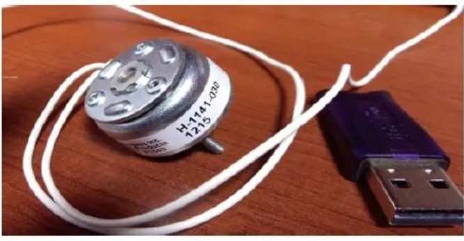
The X-Ray head is the main part of the iXRD machine and contains the X-Ray tube, shutter, solenoid and sensing platform. The Ray tube is responsible for producing Ray radiation, and the shutter is the socket that controls the flow of radiation from the X-Ray head to the target material. Opening and closing of the shutter is controlled by a 45- degree H-1141-030 LEDEX rotary solenoid [19] that is shown in Figure 5. Various sensors responsible for measuring temperature, detecting focus, checking the status of the shutter and X-Ray tube are located in the head. Each sensor, with the help of three wires, is connected to the PLC, which is mounted inside the XRD box. The distance between the X-Ray head and the XRD box, where PLC sits is about two meters. A lot of wiring is needed between X-Ray head and the XRD box as each sensor needs three wires to connect it to the PLC. The new system must be designed to reduce this wiring complexity, reduce cost, and increase overall reliability.
Figure 5 - LEDEX Rotary Solenoid
12
The detector on the machine is responsible for detecting the reflected X-Ray and converting it into an electrical signal. The reflected X-Ray first falls onto a phosphorous thin sheet that converts it to the visible light and then using fiber optic this light is transferred onto the surface of 512 pixels photodiode, which converts visible light to electrical signal. This electrical signal is fed into an Analog to Digital Converter (ADC) board and the digital value is sent to the PC through a dedicated USB port.
The PLC used for the automation is housed inside the XRD box and control to turn on/off the system is provided on the front panel of the XRD box. The XRD box also has current, voltage and status indicators. The XSA board needs to be designed such that it can fit inside the X-Ray head and near to all sensors thus leaving only the high voltage power control board inside the XRD box. In this thesis, the current design of the XRD box is used without any modifications.
13
Figure 6 - X-Ray stress measurement system architecture with PLC
2.5
RS-485 Communication Protocol
The X-Ray stress measurement system discussed in this thesis uses RS-485 communication for exchange of messages between different operating modules of the system. The background information necessary to understand this communication protocol is presented in this section.
14
reversed polarity (A +, B −) is binary 0. The standard does not assign any logic function to
these two states.
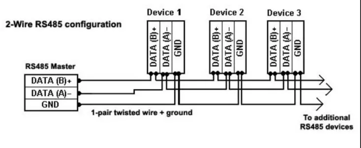
RS-485 supports inexpensive local networks and multi-drop communications links. Since it uses the differential balanced line over twisted pair RS-485 can communicate distances up to 1,200 m (4,000 ft). It offers data transmission speeds of up to 35 megabits per second (Mbps) for distances up to 10 m, and 100 kilobits per second (kbps) for distances up to 1200m [23]. RS-485 drivers use 3-state logic allowing individual transmitters to be deactivated. This allows RS-485 to implement linear bus topologies using only two wires. The 3-state logic allows an output port to assume a high impedance state in addition to the zero (0) and one (1) logic levels, effectively removing the output from the circuit. This allows multiple circuits to share the same output line or lines.
The equipment located along a set of RS-485 wires is interchangeably called nodes, stations or devices. The recommended arrangement of the wires is a connected series of point-to-point (multi-dropped) nodes as shown in Figure 7.
15
Since RS-485 does not specify any protocol, the firmware on the node is responsible for choosing the data frame. Typically, a data frame that consists of a start bit, 8 data bits and a stop bit as shown in Figure 8 is chosen.
Figure 8 - RS-485 data frame
The RS-485 bus can function in full-duplex or half-duplex mode. In half-duplex mode, two lines as shown in Figure 7 are used. In this mode, two devices connected in the bus can communicate with each other but in one direction at a time like a walkie-talkie. In contrast to this, in the full-duplex mode, two devices can communicate with each other simultaneously like a telephone. RS-485 uses four wires for this type of full-duplex communication.
2.6
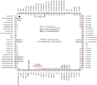
ATMEL ATMEGA-2560 Microcontroller
16
Figure 9 - ATMEL-2560 pin diagram
2.7
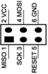
ATMEGA-2560 Programming Interface
17
Figure 10 - SPI interface
2.8
Summary
In this chapter, few limitations of PLCs and challenges faced by OEMs by using programmable logic controllers for automation of their machines are discussed. PLC’s
18
3.
DESIGN AND IMPLEMENTATION
3.1
Introduction
The design and implementation of the MCU-based X-Ray System Automation board proposed in this thesis are carried out in the following phases:
o Requirements analysis
o System design
o Hardware design
o Software design and implementation
A detailed discussion of these phases is presented in this chapter.
3.2
The Design and Implementation Methodology
3.2.1 Requirements Analysis
The MCU-based embedded control system proposed in this thesis for the automation of the Proto Manufacturing X-Ray stress measurement system shall
- Have faster response time as compared to PLC-based automation - Reduce system complexity and improve scalability
- Reduce system integration and maintenance cost
19
The existing system has many wires running from the X-Ray head to the XRD box where the PLC is located. RS-485 communication lines that connect PLC, PC and M-drive motors are also running along the same path. This has increased the wiring complexity in the system. To eliminate this wiring complexity the XSA board designed in this thesis must be small enough to fit inside the X-Ray head. By placing the XSA board inside the X-Ray head, all wires running from head to XRD box can be eliminated to get clean and simple wiring. With this change, scalability of the system is improved as new sensors can be easily added to the system for more features when desired.
Eliminating the PLC from the system results in a significant cost reduction as PLC is the highest cost factor in all OEM automation solutions. To achieve further cost savings, components used in the design of the XSA board must be carefully chosen. Achieving reduced wiring complexity is also necessary to reduce integration and maintenance cost.
Following sections of this chapter will explain in detail how these requirements are addressed while designing the XSA board.
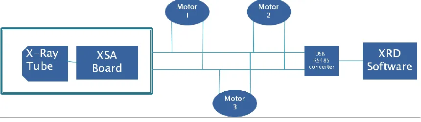
3.2.2 System Design
20
Figure 11 - X-Ray stress measurement system architecture with XSA board
3.2.3 XSA Board Design
The block diagram of the XSA board designed in thesis is as shown in the Figure 12. The ATMEGA-2560 MCU is interfaced to auto focus, shutter present, shutter status, temperature and high voltage sensors through dedicated signal conditioning circuits for each sensor. Different hardware modules used in designing this hardware board are discussed below.
21
3.2.3.1 MCU Selection
Choosing the right MCU for the design of the XSA board was the one of the important parts of this thesis. The selected MCU was supposed to have small package as the size of the XSA board itself had a limitation not to exceed the size of the head. In addition, firstly, it should have at least 8MHz operating frequency and support multiple sensor interfaces. Secondly, it should be a low cost MCU and easily available in the market. Finally, it should be easy to program.
After significant study, Atmel’s ATMEGA-2560 MCU was chosen because, it has the
maximum operating frequency of 16MHz, has 100 pins to support different types of sensor interfaces. It is also a low cost MCU with high availability. It is available in Thin Quad Flat Package (TQFP), which is small and takes less space on the PCB. ATMEGA-2560 can be easily programmed in C programming language using Atmel’s Atmel Studio
Integrated Development Environment (IDE) tool.
3.2.3.2 Sensors Interface
For the ATMEL-2560 microcontroller to be able to read various system parameters such as temperature, sensors must be connected to the microcontroller through proper hardware interfaces. These interfaces provide the power, grounding and other signal inputs necessary for the sensor to convert the physical quantity such as temperature to electrical signals that are fed to the microcontroller. The design of various hardware interfaces used in the proposed XSA board is discussed in the sections that follow.
Temperature sensor interface
22
Figure 13: Temperature sensor interface circuit
Figure 14 - Comparator circuit
Proximity Sensor (E2EC-CR5C1 2M)
23
status from the proximity sensor. The controlling application then moves the X-Ray head until it is at a known distance from the object being scanned. The head will then move up to the predefined focus position to complete the autofocus process. The schematic of the proximity sensor is shown in Figure 15.
Figure 15 - Proximity Sensor
Photomicrosensor (EE SX1018)
Before starting a measurement, the X-Ray stress measurement system needs to check the presence of X-Ray tube and shutter. To implement this requirement, I designed simple circuits as shown in Figure 16 using EE SX1018 photomicrosensors [28] and [29]. The sensor circuits produce a high level (1) when the presence of the tube or shutter is detected and low level (0) when the absence is detected. The outputs of these sensors are connected to digital input pins of the MCU. Software will read these pins when it gets request from XRD software and updates the status back to the software.
24
The control application running on the PC needs to know the status (Open/Close) of the shutter before it could start a measurement. I implemented this requirement also using the same EE SX1018 photomicrosensor. The output of this circuit is connected to an input pin of the MCU and read by the software whenever the control application requests for shutter status.
Figure 16 – Photomicrosensors circuit
DRV101:U9 – Solenoid driver
I designed a circuit to drive the LEDEX rotary solenoid used in controlling the opening and closing of the X-Ray tube shutter using the solenoid driver DRV101 [30]. The DRV101 is a low-side power switch employing a Pulse-Width Modulated (PWM) output and its schematic is shown in Figure 17.
25
Figure 17 - DRV101
The input pin (1) of DRV101 is connected to a digital output pin of microcontroller and is controlled by the software. When the “Shutter Open” command is received from the control application running on the PC, the XSA software will set high (1) level on this pin to open the shutter. When it receives the “Shutter Close” command, it will set low (0) on
this pin to close the shutter.
It is required to have high pull-in current to drive the solenoids because they have a much higher pull-in current requirement than hold requirement. I achieved this by connecting a capacitor between pin (2) and ground. The capacitance of this delay adjustment capacitor is calculated by using Equation-1.
Delay Time = C.106 s (Time in second, C in Farad) (1)
In the proposed XSA board, for a preset delay of 0.22 milliseconds a 0.22 nf (nano farad) capacitor is connected in this circuit.
The duty cycle is adjusted by connecting pin (3) to the input of a comparator and a 19kΩ resistor to ground. It is driven by a 200µA current source from VS. The voltage at this node
26
program the duty cycles and the required resistor value is calculated as 25kΩ using Equation-2.
RPWM = [a + b (DC) + c (DC)2 + d (DC)3 + e (DC)4]–1 (2)
Where: a = 2.4711 x 10⁻⁶, b = –5.2095 x 10⁻⁷, c = 4.4576 x 10⁻⁸
d = –7.6427 x 10⁻¹⁰, e = 6.8039 x 10⁻¹², DC = Duty Cycle
At a temperature T = +25°C and supply voltage = +24Vc
RC low-pass filter
While designing the XSA board, there was a problem of high frequency noise from the main DC input signal, sensors and the through holes in PCB board. This high frequency noise affected signal levels on the system and the voltage regulator and solenoid driver. To eliminate this high frequency noise, I designed a Resistor-Capacitor (RC) low-pass filter [31], as shown in Figure 18. This filter passes signals with a frequency lower than a certain cutoff frequency and attenuates signals with frequencies higher than the cutoff frequency. In the proposed system, I designed an RC-low pass filter with the cutoff frequency of 50Hz using the equation RC = 1/2πf. With f=50Hz, RC product is 0.00318FOhm which is approximately achieved using a 30kΩ resistor and a 100nf capacitor.
Figure 18 - RC-low pass filter
Voltage Regulator
27
KA78M05TUFS [32] from Fairchild Semiconductor which gives a steady 5V DC output for inputs ranging from 12V to 18V.
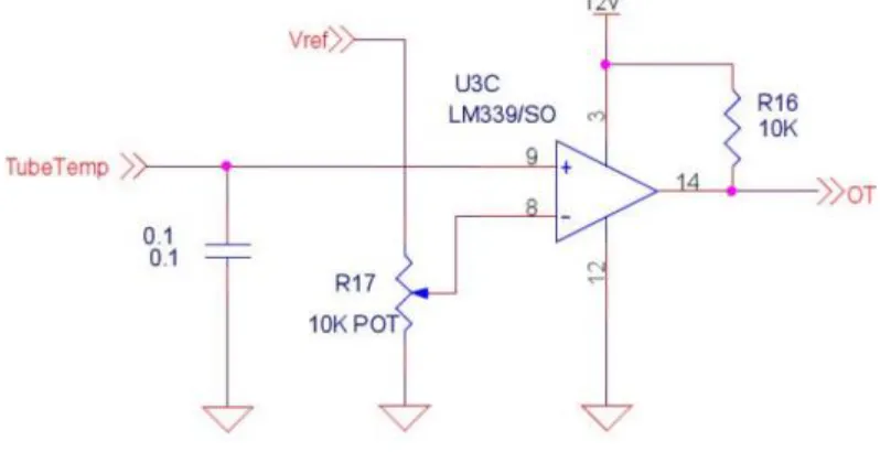
Temperature comparator
The X-Ray stress measurement systems should not operate if the temperature inside the X-Ray head is more than 70°C. This is a requirement taken from the existing system. This could have been implemented in either software or hardware. Implementing this requirement in software would mean using lot of processing time of MCU which could affect the systems response time. Therefore, I decided to design a temperature comparator circuit using the LM339 [33], that could interrupt the MCU when the temperature inside the X-Ray head is greater than 70°C.
In the proposed system, this device is used to compare the output voltage (TubeTemp) of temperature sensor AD590 with the reference voltage (Vref) corresponding to a pre-set temperature value which is 70°C. The temperature comparator circuit used in the proposed system is as shown in Figure 19. The circuit will output a logic low or high impedance (logic high with pull-up) based on the inputs difference. The output of this circuit is connected to an interrupt pin of the ATMEGA-2560 MCU. This interrupt is triggered when the temperature is greater than 70°C and Interrupt Service Routine (ISR) is invoked. The ISR will close the X-Ray head shutter to stop the measurement.
28
RS-485 Transceiver
29
Figure 20 - MAX3491 Transceiver
XSA Board Schematic and PCB Layout
30
Figure 21 - Hardware schematic and the PCB layout of XSA board
Table 1 - Hardware Components on PCB
Number Hardware Component
1 ATMEGA-2560 MCU 2 DRV 101 Solenoid Drive 3 Voltage Regulator
4 MAX3491 RS-485 Transceiver 5 Microcontroller PORTD Connections 6 RC Filter
7 SPI Interface
3.2.4 SW Design and Implementation
31
popular C programming language; which is widely used for coding embedded controller software, is used in writing software code of the X-Ray system automation board. In the development phase, module level (unit testing) and integration testing are performed. A detailed system testing is then carried out to analyze the in-system performance of the XSA board hardware and software in real time. Detailed information about software layers, software modules, and their execution pattern is given in this section.
3.2.4.1 SW Architecture
Structurally, the software of the X-Ray automation board is divided into two layers: application layer and middleware layer. The software modules that contain the source code for handling the core machine functions such as closing and opening the X-Ray head shutter are classified as the application layer. The modules that link the application layer with the hardware by providing access to the microcontroller resources such as timers, digital inputs etc. are middleware layer modules.
Different behavioral software architectures as discussed in [35] are in use in designing software for embedded control systems. For the design and development of the software for the X-Ray system automation board proposed in thesis, “round robin with interrupts” architecture is the most applicable because the system has very minimal set of functionalities that can be implemented on the ATMEGA-2560 microcontroller without any real-time operating system. The “round robin with interrupts” architecture is preferred in this thesis over the basic “round robin” architecture because it suffers from the same sequential execution problem of the PLC that was discussed in earlier chapters in this thesis. Using the sequential execution for low priority tasks and interrupts for high priority tasks improves the system response time for critical events.
Software Component Diagram
32
module in the application layer. The software modules that process the RS-485 communication messages and handle Light Emitting Diode (LED) and switch are also placed in the application layer.
The application layer software components use middleware components mainly to interact with the microcontroller and in turn with the hardware and sensors of the X-Ray stress measurement system. The middleware also provides the utility functions and data structures such as serial communication buffers, message queues etc. to the application layer. In the XSA board software, the middle layer consists of three major components namely, timer initialization, interrupt setup and serial USART communication. There is also an SPI communication module and a miscellaneous initialization module available in middleware for the use of application layer functions.
33
Figure 22 - Software component architecture
Software Behavioral Diagram
34
Figure 23 - Software behavioral architecture
Table 2. When any interrupt occurs, the execution will jump from the idle task to interrupt service routine of that interrupt. This switching will happen based on the entries in the interrupt vector table initialized in ATMEGA-2560 microcontroller by the
35
Table 2 - List of interrupts used in XSA board software
Interrupt Name Description Priority
Over temperature interrupt
Occurs when the temperature inside the X-Ray head is more than 70˚Centigrade
0
Shutter not OK interrupt
Occurs if the shutter has been removed from its place on the head
1
Timer0 interrupt A periodic interrupt that occurs every 25 milliseconds
3
RS-485 receiver interrupt
When a character is received by the ATMEGA-2560 microcontroller that was transmitted on RS-485 bus by PC this interrupt is triggered
4
RS-485 transmit interrupt
When the XSA board software wants to send an RS-485 message, it instructs the USART module of the microcontroller by copying the byte to be transmitted on to transmit data register. On completing transmission of this byte, this interrupt is triggered. The ISR of this interrupt will copy the next byte to be transmitted into transmit data register. This process will continue until all bytes are transmitted
36
completely and USART transmit interrupt is disabled
3.2.4.2 Application Layer
The application layer of the XSA board software has following software modules:
i. Main
ii. Interrupt service routines iii. RS-485 message processing iv. LED/Switch handlers
Each of these modules contain functions written in C programming language. Algorithm of each function, inputs taken and outputs produced are discussed in the following sections.
Main
37
38
Interrupt Service Routines
For each interrupt listed in
Table 2, an interrupt service routine is designed in this thesis. The algorithms of these interrupt service routines are explained in the below sections.
Timer0 compare ISR
39
40
INT2 ISR
This is the ISR for the shutter not OK interrupt that occurs if the shutter is not detected on the head. The ISR just calls the close function to update the digital output status and send a message to the PC to indicate the failure condition.
INT0 ISR
41
USART0_UDRE_vect
42
43
USART0_RX_vect
44
45
RS-485 Message Processing
The RunMenu task which runs every 100 milliseconds is responsible for processing all RS-485 messages. “Open Shutter”, “Close Shutter” and “Status” are RS-485 messages that the XSA board receives from the PC. For each received message, the board sends a response message that has success, failure or status information. The RunMenu function starts by reading all the characters available in the received circular buffer followed by checking the received characters for “AA” which is the RS-485 node address of the XSA
board. If the address is matched, it continues to analyze the received characters to identify the received message. If the received message is “Open Shutter”, the Sensors function is
called to check the status of X-Ray tube and shutter. When the Sensors function returns all OK status, the shutter is opened and a “Success” message is sent to the PC. Similar steps are followed in processing the “Close Shutter” message. When PC requests “Status”
message, the Status function is called to check the status of X-Ray tube and shutter. On completing the status check, the function will send “Tube is good” or “Tube is open”, and “Shutter is open” or “Shutter is closed” messages to the PC.
LED/Switch handling functions
The initPorts function is implemented to initialize PORTB of the ATMEGA-2560 microcontroller as the output port and PORTD as the input port. This is achieved by writing the corresponding port Data Direction Register (DDR) [24]. Setting the DDR register to 0x00 configures a port as an input port and the value 0x11 configures the port as an output port.
3.2.4.3 Middleware Layer
The middleware layer of the XSA board software has following software modules:
i. Timer functions
ii. Interrupt setup functions
iii. Serial communication (USART) functions iv. SPI communication function
v. Miscellaneous controller initialization functions
46
Timer Functions
The ISR_InitTimer0 function is implemented to initialize the Timer0 module of the microcontroller to produce a periodic interrupt of 25 milliseconds. A value of 197 is loaded to the Output Compare Register (OCR) [24] of Timer0 to achieve the 25 milliseconds duration with the 8 MHz Central Processing Unit (CPU) clock used in the design of the XSA board.
Interrupt Setup functions
A simple ClearInterrupt function is implemented to clear the external interrupt flags in the microcontroller as per needs of the application. Clearing of interrupts is needed inside the interrupt service routines to indicate to the controller that the interrupts are serviced and they can be re-enabled.
Serial Communication (USART) functions
Three functions are implemented in this thesis for the operation of the serial communication interface to send and receive RS-485 messages. The SCIInitialize function initializes the USART0 of the ATMEGA-2560 microcontroller with 9600 baud rate, 8 data bits and odd parity configuration. It also enables the receive interrupt and initializes receive and transmit circular buffers.
The SCIWriteString function takes a null-terminated string as input and copies it to transmit circular buffer zOutputChars. It then enables the USART0 transmit interrupt to start the transmission of input string one character at a time until all characters are transmitted.
The SCIReadChar function checks if the receive circular buffer zInputChars is empty and if it is not, it returns the character at the top of the buffer to the calling function. It then moves the buffer read pointer to the next character.
SPI functions
47
programming. It also sets clock phase, polarity and clock rate parameters by writing the desired values to the SPI Control Register (SPCR) [24].
Miscellaneous Controller Initialization Functions
In addition to the functions discussed in different sections above, simple utility functions to select the functionality of each pin, initialization of the clock are implemented in the XSA board software.
3.3
Summary
48
4.
RESULTS AND CONCLUSION
4.1
Introduction
In this section, the response time of the PLC for changes in the input are compared with the response time of the XSA board for same inputs. A test application was developed to measure the response time of the MCU-based XSA board. The complexity and scalability of the system is analyzed with reference to the PLC-based system. The conclusion of this thesis and future work are discussed at the end of the chapter.
4.2
Response Time Analysis
The response times of the PLC and the MCU-based XSA board for different sensor inputs are listed in the Table 3.
Table 3 - Response Times of XSA board and PLC
Sensors Response Time in milliseconds
XSA Board PLC Automation
Temperature Sensor 0.087 9.67 Temperature Sensor and
Shutter OK Sensor 0.172 9.93 Temperature Sensor,
Shutter OK and Tube OK Sensor
0.264 10.15
49
Meanwhile, the PLC would take 9.67 milliseconds to respond to the same event. It should also be noted that, the PLC would scan the temperature input during every input scan process. However, the MCU would work on the temperature sensor input only when temperature is greater than 70˚C.
When any event occurs independently, there is no competition for the MCU time with other events and the MCU will respond to it in 0.087 milliseconds. When two or more events occur at the same time or an event occurs when another event is being processed, the MCU will handle events based on their priority. Multiple sequences of events are possible with multiple inputs. In the following section two sequences are discussed to understand the priority based event handling.
Sequence 1: Shutter not OK event occurs, while the over temperature event being
processed
When the events occur in this sequence, the processing of over temperature event will continue without any affect, because, the shutter not OK even is assigned with lower priority than the over temperature event in the MCU software. When the MCU finishes processing the over temperature event, it will start processing the shutter not OK event and it would take 0.0172 milliseconds to start processing it.
Sequence 2: Over temperature event occurs while the shutter not OK event being
processed
In this sequence, since I have assigned the highest priority to the temperature sensor input the MCU will give immediate attention to it and start handling over temperature event by pushing the processing of shutter not OK event to the background. Once it completes handling the over temperature event, it will resume the processing of the shutter not OK event.
50
4.3
System Complexity Analysis
Currently, the head contains five sensors. Each sensor connection needs a dedicated data line, a power supply line and a ground line. A common power supply line and a ground line are used for all sensors. In addition, there are four RS-485 communication lines connecting PLC, M-Drive motors and PC. Thus, many wires are running from the X-ray head to the XRD box in a complex way. This wiring complexity is reduced significantly in the proposed design. The small form factor of the XSA board allows it to be placed inside the X-Ray head itself. Hence, all wires that were running from the X-Ray head up to the XRD box to connect different sensors to the PLC are now not needed. The proposed design has only 12V power line, a ground line running from X-Ray head to the XRD box. There are also four communication lines that run from XRD box to the M-drive motors and PC.
4.4
System Scalability Analysis
51
Figure 28 - Scalability Vs Complexity
4.5
Cost Savings Analysis
52
Table 4 - Cost Comparison
PLC Automation XSA Board
Components Price (in $) Components Price (in $)
Trilogic PLC 350 ATMEGA-2560 8 Communication
Components 100 Other Components 10
Rack 100 PCB 30
Wiring Cost (5 sensors; 15 wires –
30 meter)
50 Soldering 40
Total 600 88
4.6
Conclusion and Future work
The X-Ray system automation board proposed and designed in this thesis is an effective replacement to the PLC-based automation framework and meets all the system design requirements. Through computation and analysis, the proposed design has improved the system response time by employing an interrupt driven software architecture to cater to the higher priority inputs. The wiring complexity of the system is significantly reduced as the XSA board can be now placed inside the X-Ray head because of the small form factor of the MCU-based board. With the reduced wiring complexity, the scalability factor of the system is improved. New sensors can be added to the proposed system without any apparent wiring changes. Elimination of high-cost PLC and reduced wiring requirement has drastically reduced the system cost. The total cost of the new system is less as it is designed from scratch using basic components needed to fulfill the design requirements.
53
54
REFERENCES:
[1] NDT Resource Center. (2016, September) History of Radiography. [Online].
https://www.nde-ed.org/EducationResources/CommunityCollege/Radiography/Introduction/history. htm
[2] GZ Yue et al., "Generation of continuous and pulsed diagnostic imaging x-ray radiation using," Applied Physics Letters, no. 81(2), p. 355-357, 2002.
[3] School of Chemistry, University of Bristol. (2016, September) Discovery of X-rays and some of their uses. [Online].
http://www.chm.bris.ac.uk/webprojects2001/cdavies/xrays.htm
[4] Proto Manufacturing. (2016, September) Products Overview. [Online].
http://www.protoxrd.com/products.html
[5] Aliasgar et al., "Automated Pick and Place System," in International Conference on Mechanical and Electrical Technolog (ICMET 2010), Bangalore, 2010, pp. 682-686.
[6] Bosch Rexroth Corp. (2011, Nov.). Control Engineering. [Online].
http://www.controleng.com/single-article/inside-machines-pc-versus-plc-comparing-control-options/9bf8690c6f23b11370bec90b52cb15c9.html
[7] Agustin Rullan, "Programmable logic controllers versus personal computers for process," Computers & industrial engineering, vol. 1, no. 33, pp. 421-424, 1997.
[8] Wikipedia. (2016, September) IEC_61131-3. [Online].
https://en.wikipedia.org/wiki/IEC_61131-3
[9] Mohamed Er Rida, Fuqiang Liu, and Yassine Jadi, "Design mini-plc based on on ATxmega256A3U-AU," in Information Science, Electronics and Electrical Engineering (ISEEE), vol. 2, 2014 International Conference, pp. 1034-1037.
[10] NA Ivanescu, Th Borangiu, S Brotac, and A Dogar, "Implementation of sequential charts with microcontrollers," in Control & Automation. Mediterranean
55
[11] Atmel Corporation. (2014) Atmel-2549-8-bit-AVR-Microcontroller. [Online].
http://www.atmel.com/Images/Atmel-2549-8-bit-AVR-Microcontroller-ATmega640-1280-1281-2560-2561_datasheet.pdf
[12] Ernie Hayden, Michael Assante, and Tim Conway. (2014, August) An Abbreviated History of Automation & Industrial Controls Systems and Cybersecurity. A SANS Analyst Whitepaper.
[13] J. F. Hooper, Introduction to PLCs, Second Edition ed. Durham, North Carolina, USA: Carolina Academic Press, 2006.
[14] W. Bolton, Programmable Logic Controllers, Fourth edition ed. Burlington, MA: Elsevier Newnes, 2006.
[15] Dong Yulin and Zheng Chunjiao, "Design and Research of Embedded PLC Development System," in Computer Research and Development (ICCRD), 2011 3rd International Conference, vol. 3, 2011, pp. 226-228.
[16] Dhanashri Gawali and V.K.Sharma, "FPGA BASED MICRO-PLC DESIGN APPROACH," in International Conference on Advances in Computing, Control, and Telecommunication Technologies, 2009, pp. 660-663.
[17] Min Jin, Xiang Zhou, and Jihui Zhou, "Research of Embedded Motion Controller for Construction Machinery," in Embedded Computing, 2008. SEC '08. Fifth IEEE International Symposium, 2008, pp. 201-206.
[18] Jianxin Zhang and Zhiyu Zhou, "A Batch Dyeing Machine’s Controller Based on Embedded System," in International Conference on Artificial Intelligence and Computational Intelligence, 2009, pp. 429-432.
[19] Johnson Electric. (2016). Solenoids. [Online].
http://www.johnsonelectric.com/en/product-technology/motion/solenoids/
[20] Schneider Electric Motion USA. (2016). MDrivePlus products. [Online].
http://motion.schneider-electric.com/products/mdriveplus_overview.html
[21] Schneider Electric Motion. Programming and Software Refrence for: M-Code. Electronic Source.
[22] Manny Soltero et al. (2010, May). Texas Instruments Incorporated Web site. [Online]. http://www.ti.com/lit/an/slla070d/slla070d.pdf
[23] Inc Wikimedia Foundation. (2016, November). RS-485. [Online].
56
[24] Atmel Corporation. (2016). Atmel-2549-8-bit-AVR-Microcontroller. [Online].
http://www.atmel.com/Images/Atmel-2549-8-bit-AVR-Microcontroller-ATmega640-1280-1281-2560-2561_datasheet.pdf
[25] Wikipedia Foundation Inc. (2016, November). Serial Peripheral Interface Bus. [Online]. https://en.wikipedia.org/wiki/Serial_Peripheral_Interface_Bus
[26] Analog Devices, Inc. (2016, January). AD590. [Online].
http://www.analog.com/media/en/technical-documentation/data-sheets/AD590.pdf
[27] Omron Corporation. (2016). E2EC-CR5C1 2M. [Online].
https://www.ia.omron.com/product/item/1017/
[28] Omron Corporation. (2016, May) EE-SX1018 Photomicrosensor. [Online].
https://www.omron.com/ecb/products/photo/34/ee_sx1018.html
[29] Omron Corporation. (2016, June) Micro Sensing Device Data Book. [Online].
https://www.omron.com/ecb/products/pdf/en-scec-001d-1.pdf
[30] Texas Instruments Incorporated. (1998, January). PWM SOLENOID/VALVE DRIVER. [Online]. http://www.ti.com/lit/ds/symlink/drv101.pdf
[31] Jong Ryul Lee, et al., "Low pass filter," US Patent 6,091,289, July 18, 2000.
[32] Fairchild Semiconductor Corporation. (2015, January) 3 Terminal 0.5A Positive Voltage Regulator.
[33] Texas Instruments Incorporated. (2016) LMx39x, LM2901xx Quad Differential Comparators. [Online]. http://www.ti.com/lit/ds/symlink/lm339.pdf
[34] Maxim Integrated. (2016, November) MAX3491. [Online].
https://www.maximintegrated.com/en/products/interface/transceivers/MAX3491.h tml
[35] J. A. Cook and J. S. Freudenberg. (2008, September) Embedded Software Architecture. Document.
57
APPENDIX
A.
Interrupt Vectors in ATMEGA-2560
Vector No.
Program Address
Source Interrupt Definition
1 $0000 RESET External Pin, Power-on Reset, Brown-out Reset, Watchdog
Reset, and JTAG AVR Reset 2 $0002 INT0 External Interrupt Request 0 3 $0004 INT1 External Interrupt Request 1 4 $0006 INT2 External Interrupt Request 2 5 $0008 INT3 External Interrupt Request 3 6 $000A INT4 External Interrupt Request 4 7 $000C INT5 External Interrupt Request 5 8 $000E INT6 External Interrupt Request 6 9 $0010 INT7 External Interrupt Request 7 10 $0012 PCINT0 Pin Change Interrupt Request 0 11 $0014 PCINT1 Pin Change Interrupt Request 1 12 $0016 PCINT2 Pin Change Interrupt Request 2 13 $0018 WDT Watchdog Time-out Interrupt 14 $001A TIMER2
COMPA
Timer/Counter2 Compare Match A
15 $001C TIMER2 COMPB
Timer/Counter2 Compare Match B
16 $001E TIMER2 OVF
Timer/Counter2 Overflow
17 $0020 TIMER1 CAPT
Timer/Counter1 Capture Event
18 $0022 TIMER1 COMPA
Timer/Counter1 Compare Match A
19 $0024 TIMER1 COMPB
Timer/Counter1 Compare Match B
20 $0026 TIMER1 COMPC
Timer/Counter1 Compare Match C
21 $0028 TIMER1 OVF
Timer/Counter1 Overflow
22 $002A TIMER0 COMPA
58 23 $002C TIMER0
COMPB
Timer/Counter0 Compare match B
24 $002E TIMER0 OVF
Timer/Counter0 Overflow
25 $0030 SPI, STC SPI Serial Transfer Complete 26 $0032 USART0 RX USART0 Rx Complete 27 $0034 USART0
UDRE
USART0 Data Register Empty
28 $0036 USART0 TX USART0 Tx Complete 29 $0038 ANALOG
COMP
Analog Comparator
30 $003A ADC ADC Conversion Complete 31 $003C EE READY EEPROM Ready
32 $003E TIMER3 CAPT
Timer/Counter3 Capture Event
33 $0040 TIMER3 COMPA
Timer/Counter3 Compare Match A
34 $0042 TIMER3 COMPB
Timer/Counter3 Compare Match B
35 $0044 TIMER3 COMPC
Timer/Counter3 Compare Match C
36 $0046 TIMER3 OVF
Timer/Counter3 Overflow
37 $0048 USART1 RX USART1 Rx Complete 38 $004A USART1
UDRE
USART1 Data Register Empty
39 $004C USART1 TX USART1 Tx Complete 40 $004E TWI 2-wire Serial Interface 41 $0050 SPM
READY
Store Program Memory Ready
42 $0052 TIMER4 CAPT
Timer/Counter4 Capture Event
43 $0054 TIMER4 COMPA
Timer/Counter4 Compare Match A
44 $0056 TIMER4 COMPB
Timer/Counter4 Compare Match B
45 $0058 TIMER4 COMPC
Timer/Counter4 Compare Match C
46 $005A TIMER4 OVF
Timer/Counter4 Overflow
47 $005C TIMER5 CAPT
Timer/Counter5 Capture Event
48 $005E TIMER5 COMPA
59 49 $0060 TIMER5
COMPB
Timer/Counter5 Compare Match B
50 $0062 TIMER5 COMPC
Timer/Counter5 Compare Match C
51 $0064 TIMER5 OVF
Timer/Counter5 Overflow
52 $0066 USART2 RX USART2 Rx Complete 53 $0068 USART2
UDRE
USART2 Data Register Empty
54 $006A USART2 TX USART2 Tx Complete 55 $006C USART3 RX USART3 Rx Complete 56 $006E USART3
UDRE
USART3 Data Register Empty
60