arXiv:hep-ex/9710021v1 23 Oct 1997
Department of Physics & Astronomy
Experimental Particle Physics Group
Kelvin Building, University of Glasgow,Glasgow, G12 8QQ, Scotland
Telephone: +44 (0)141 339 8855 Fax: +44 (0)141 330 5881
GLAS-PPE/97–09
October 1997
CP Violation and Future ‘B-Factories’
N. H. Brook
Lecture given at “The Actual Problems of Particle Physics”, Gomel, Belarus.
Abstract
1
CP Violation in the B-system
Quark mixing in the standard model is described by the Cabibbo-Kobayashi-Maskawa (CKM)
matrix [1], eqn(1). Conventionally theu, cand tquarks are unmixed and the mixing is described
by the 3×3VCK M matrix operating on the d, s and b quarks. The matrix elements of VCK M
can, in principle, be determined by measuring the charged current coupling to theW± bosons.
VCK M ≡
Vud Vus Vub Vcd Vcs Vcb Vtd Vts Vtb
(1)
The CKM matrix is unitary ie VCK M† VCK M = 1, which leads to 9 unitarity conditions
expressed in terms of the matrix elements. There are several (approximate) parameterisations of the CKM matrix, one of the more popular approaches is that of Wolfenstein [2], eqn(2),
where the matrix elements are expressed in terms of powers of λ = sinθc, where θc is the
Cabibbo angle. As can be seen from this parameterisation, the 9 complex elements of the
matrix can be expressed in terms of 4 independent variables; three real parameters A, λ and ρ
and an imaginary part of a complex number, η. The 18 parameters of the CKM matrix can be
reduced to 4 because of the unitarity constraints and the arbitrary nature of the relative quark
phases [3]. It is the complex phase in the VCK M that leads to CP violation in the standard
model.
VWolfenstein =
1− 12λ2 λ Aλ3(ρ−iη)
−λ 1−1
2λ
2
Aλ2 Aλ3(1−ρ−iη) −Aλ2 1
(2)
The unitarity condition
VudVub∗ +VcdVcb∗ +VtdVtb∗ = 0
is of particular interest since Vud ≃ Vtb ≃ 1 and Vts∗ ≃ −Vcb. This allows us to depict this
condition as a triangle in the complex plane, as shown in fig 1. The angles of the triangle
α, β and γ are related to the phase and can be measured in CP violatingB-decays.
The non-closure of this triangle ieα+β+γ 6=π would suggest that our understanding of CP
violation within the Standard Model was incomplete. Physics beyond the Standard Model can
be further investigated, for example, by measuring CP asymmetries in several B decays that
depend on the same unitarity angle or studying decays where zero asymmetries are expected in the Standard Model.
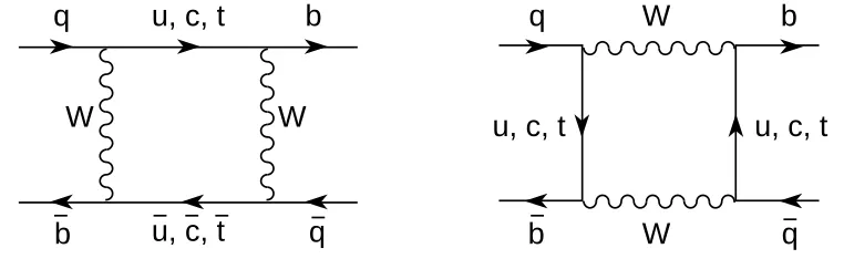
CP violation in the B system should be observable through the phenomenon of B0 − ¯
B0
mixing, see for example [4]. This B0−B¯0 mixing is dominated by box-diagrams with virtual
Figure 1: The CKM unitarity triangle in the Wolfenstein parameterisation
q
u, c, t
b
q
b
u, c, t
W
W
q
b
W
q
b
u, c, t
u, c, t
W
Figure 2: B0−B¯0 mixing diagrams.
The following decays
B0
d → J/ψK
0 s
B0
d → π
+
π− (3)
B0
s → ρK
0 s
are into a CP eigenstate. If this is coupled with only a single diagram contributing to the decay, CP asymmetries can be constructed which are directly related to the angles of the unitarity
triangle. For example, these conditions occur for the decay mode B0
d → J/ψK
0
s. Here the
number of B0
d which decay at time t (wheret is expressed in units of lifetime) is proportional
to
n(t)∝e−t
(1 + sin 2βsinxt) (4)
and the number of ¯B0
d is proportional to
¯
n(t)∝e−t
where the mixing parameter, x = ∆M/Γ ≃ 0.67, is the ratio of the mass difference of the eigenstates to their decay rate. The CP asymmetry can then be defined as
a(t) = n(t)−¯n(t)
n(t) + ¯n(t) = sin 2βsinxt.
By integrating eqns. (4) and (5) over time a similar asymmetry can be constructed which
is proportional to sin 2β. (Although for coherent B production ie the BB¯ pair is produced
in a definite CP state, this time integrated asymmetry is zero.) In addition this channel
is experimentally very promising because of the dilepton decay of the J/ψ. Unfortunately
additional decay diagrams contribute to the other channels listed in eqn(3) so there is no longer
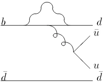
a complete cancellation of the hadronic matrix elements in the CP asymmetry. TheB0
d →π
+ π−
channel, which is dependent on the angleαis predicted to have large hadronic corrections from
‘penguin’ diagrams, fig. 3. The B0
s → ρK
0
s (dependent on the angle γ) also has additional
hadronic contributions but, in addition, suffers from a very low branching fraction. Fortunately there are, of course, many other channels which can be used to measure CP violation, eg see ref. [5].
b d
@
@ u
u
d
d
Figure 3: ‘Penguin’ contribution to B0
d →π
+π− decay
2
B-Production Facilities
Because of the small visible branching ratios of decays to CP eigenstates, O(10−5
), a large
number of B meson must be produced in order to study CP violation in the B system. There
are two complimentary ways to achieve the necessary large number ofB mesons. The first is at
e+
e− colliders at centre of mass energy of 10 GeV to produce the Υ(4S) which then decays to
two B mesons. Alternatively high energy hadron machines, where there is a large cross section
for b¯b production, can be used to produce the B mesons. The pros and cons of the various
approaches are discussed in this sections.
2.1
e
+e
−Colliders
B meson production via e+
e− colliders is being pursued at laboratories in the United States
(Cornell and SLAC) and Japan (KEK). The luminosity at these machines is of theO(1033) cm−2s−1
which is equivalent to approximately 4 b¯b pairs produced every second. Because the B mesons
produced from the decay of Υ(4S) are coherent it is necessary to be able to measure the time
separation between the two B’s in order to measure the CP asymmetry throughB0−B¯0 mixing.
thus the distance between the two B mesons to be measured, the beam energies at SLAC and KEK are asymmetric. The Cornell B-facility has symmetric beam energies and will be unable
to measure CP asymmetry through B0−B¯0 mixing though there are possibilities to measure
CP violation through the decays of chargedB’s. The KEK and SLAC facilities are asymmetric
with e−(e+
) energies of 3.5 GeV (8 GeV) and 3.1 GeV (9 GeV) respectively. The need for the large luminosity and the asymmetric beam energies poses great challenges on the machine
design. The advantages of this approach is the very clean production environment of the 2 B
mesons, with no underlying event from which to extract the signal. By running at the mass of
Υ(4S) it is not possible, simply by kinematic contraints, to study the Bs system. In order to
study the Bs system the machine can be operated with energies at the mass of Υ(5S) but the
cross sections are much smaller.
2.2
Hadron Colliders
The high energy hadron machines, Tevatron and HERA (in fixed target mode with a wire target inserted into the proton beam halo), are already producing large numbers of B mesons. The
LHC will produce even greater numbers. At the Tevatron theb¯b production rate is O(104) Hz
and at LHC it will be O(105
) Hz compared to the ≃ 4 Hz at SLAC and KEK. The problem
in this approach is achieving high enough reconstruction and tagging efficiencies in order to
extract a sufficient number ofB’s to measure CP violation. The LHC has an additional benefit
over the Tevatron and HERA because with the increasing centre of mass energy the ratio of
theb¯bcross section over the total inelastic cross section also increases. All the hadron machines
also have the advantage that they can study Bs mesons.
3
The Experiments
π
π
π
µ
µ
µ
ψ
B
B
D
K
+
e
e
e
K
J/
0
-
-0 0
- - +
-S
Lepton Tag
Kaon Tag
Vertex Charge Signal B
B tag**
+
-+
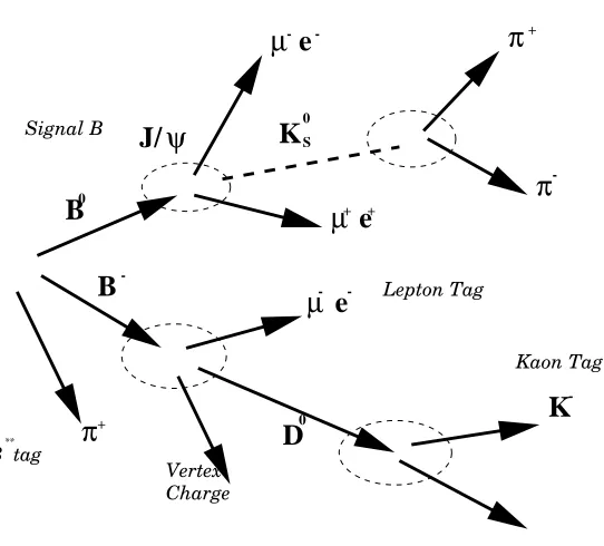
Figure 4: Example of B tagging.
To measure CP violation it is not only necessary to measure the decay of the B meson
but also to tag its initial flavour via the decay of the accompanying B, as shown schematically
has good resolution on measuring the decay time and the mass of decayed B mesons and has
particle identification to allow a good initial flavour tag of theB meson. The characteristics of
the detectors designed to study CP violation are discussed below.
3.1
BELLE
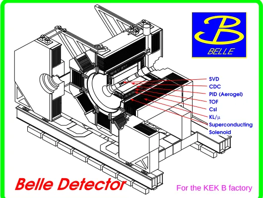
Belle Detector
For the KEK B factoryBELLE
SVD CDC PID (Aerogel) TOF CsI KL/µ
Superconducting Solenoid
Figure 5: Schematic of the BELLE detector at the KEK B factory.
The BELLE detector [6] is the experimental apparatus being designed for the KEK B factory. A schematic of the detector is shown in figure 5. The detector consist of a silicon vertex detector (SVD) situated just outside the beampipe. Surrounding that there is a cylindrical wire drift chamber (CDC) that measures charged tracks which extends to a radius of 90 cm. Particle
identification is provided by dE/dx measurements in the CDC, and aerogel ˇCerenkov counter
and time of flight (TOF) arrays situated radially around the CDC. Inside the superconducting
solenoid is a electromagnetic calorimeter manufactured from CsI(Tl) crystals. The iron return
yoke of the 1.5 Tesla solenoid is interspersed with arrays of detectors for measuring muons and
K0
L mesons. The design of the equivalent detector, BaBar, at the SLAC B factory is discussed
in ref. [7].
3.2
HERA-B
To guarantee the observation of standard model CP violation in B decays (after folding in the
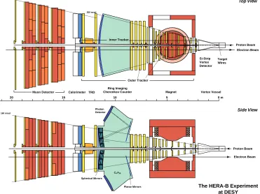
detector efficiencies), interactions at the HERA-B detector have to occur approximately 4 times for every one of the 10 MHz bunch crossings of the HERA machine. The HERA-B experiment is essentially a fixed target experiment with a wire target in the beam halo [8]. A schematic of the HERA-B spectrometer is shown in fig. 6. It has a single dipole momentum spectrometer situated 4.5 m downstream of the target. Directly downstream of the target wires, but before
the magnet, there is a silicon vertex detector of length of∼2 m.The main tracking system uses
a variety of technologies dependent on the distance away from the beam (Si-strips, microstrip gas counters and honeycomb-drift chambers at ever increasing radii from the beam.) This is
followed by a ring imaging ˇCerenkov (RICH) detector to tag the charged kaon and a
The HERA-B Experiment at DESY
Ring Imaging Cherenkov Counter
250 mrad 220 mrad
160 mrad
Magnet
Si-Strip Vertex Detector
TRD Calorimeter Muon Detector
Target Wires
0 m 5
10 15
20
Photon Detector
Planar Mirrors
Top View
Side View
Proton Beam Electron Beam
Proton Beam Electron Beam Spherical Mirrors
Vertex Vessel Outer Tracker
Inner Tracker
C4F10
Figure 6: Schematic of the HERA-B detector at DESY.
chambers immediately behind the RICH and in front of the calorimeter. The electromagnetic calorimetry is designed to use Lead/Scintillator and Tungsten/Scintillator. This is followed by a conventional muon system with four chamber layers at various depths in the absorber. The
muon chambers are essential for the triggering of HERA-B when theJ/ψdecays to two muons.
3.3
CDF and D0
There is already a very active B physics program at the CDF detector at the Tevatron. TheB
meson lifetime measurements, fig. 7, are already competetive with those of the combined LEP
experiments. This proves that it is possible to extractB physics from the hostile experimental
environment of the hadron colliders. Both CDF [9] and D0 [10] are hoping to exploit the
Tevatron upgrade (RUN II in 1999) to study CP violation in the B-system.
CDF are proposing a new tracking system for Run II, fig. 8. At large radii they will have a central outer tracker (COT) of an open drift chamber design. Inside this component there is a silicon inner tracker compromising of two components: a micro-vertex detector (SVX II) at very small radii and two additional layers of silicon at intermediate radii. The current forward calorimetry is going to be replaced with a new scintillating tile plug calorimeter. New chambers will be added to the current muon system to close gaps in the azimuthal acceptance and the forward acceptance will be improved. The trigger will also be upgraded to allow track finding at level-1 and the ability to trigger on large impact parameter tracks at level-2.
COT
0 .5 1.0 1.5 2.0
0 .5 1.0 1.5 2.0 2.5 3.0
END WALL HADRON CAL.
SVX II 5 LAYERS
30 3 00
SOLENOID
INTERMEDIATE SILICON LAYERS
CDF Tracking Volume
= 1.0
= 2.0
END PLUG EM CALORIMETER END PLUG HADRON CALORIMETER
= 3.0
n
n
n m
m
Figure 7: A comparison of CDF and
LEPB meson lifetime measurements.
Figure 8: Longitudinal View of the CDF II
Track-ing System.
muon triggers.
3.4
ATLAS and CMS
The ATLAS [11] and CMS [12] detectors at the LHC are optimised for high luminosity physics.
But initial low luminosity running will allow these general purpose detectors to used for B
physics. Both detectors are installing silicon vertex detectors close to the beampipe. More detailed discussion of these detectors and their physics performance can be found elsewhere in these proceedings [13].
0 0.5 1 1.5
2 2.5 3
0 1 2 3 0 200 400 600 800 1000
Figure 9: Production angle of B vs. angle of B in the laboratory (in units of rad.) at LHC
3.5
LHC-B
At high energy hadron colliders the produced B and ¯B mesons are correlated in the forward
direction (ie close to the proton beam direction). Figure 9 shows the angular distribution
of the BB¯ mesons in the laboratory frame at LHC. This is due to the relatively low mass
production of b quark pairs at collider energies. This production mechanism lends itself to
dedicated experiments that are of a forward, planar design, reminiscent of those used in fixed target experiments.
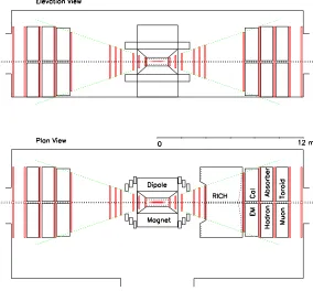
Such an experiment, LHC-B, has been proposed for the LHC [15]. Its layout is shown in figure 10. LHC-B is a forward single-dipole spectrometer It consists of a silicon microvertex detector, a tracking system, aerogel and gas RICH detectors, electromagnetic and hadronic calorimeter and a muon filter. LHC-B will be allowed to run with a defocussed beam in their
interaction area which would give a nominal running luminosity L= 1.5×1032
cm−2
s−1 .
2 m
2 m
LHC-B
Top view
p → ← p
Yoke Coil RICH-2
E-cal H-cal Muon system
Tracking chambers Mirror plate
Si vertex detector RICH-1
Figure 10: Top view of the LHC-B detector
3.6
BTeV
Recently a similarly motivated experiment (BTeV) has submitted a expression of interest at Fermilab [16]. The schematic layout of the BTeV proposal is shown in figure 11. The baseline description of the detector has a dipole magnet centred on the interaction region, thus providing the basis for a two-arm spectrometer. A vertex pixel detector (inside the magnetic field) pro-vides high resolution tracking near the interaction. The baseline design has seven downstream tracker stations of straw tubes along both arms of the spectrometer. For identification of elec-tromagnetic final states and kaons there is elecelec-tromagnetic calorimetry and a RICH detector respectively, with a toroidal magnetic detector for muon identification and measurement. The
BTeV detector relies heavily on the vertex detector for triggering of the B events.
3.7
Experimental Recap
Figure 11: Schematic Layout of the BTeV detector
is already partially instrumented and is already taking data in situ in order to debug and test some of their detector components. They have already achieved the multiple interaction per bunch crossing that is necessary to meet their design considerations. CDF and D0, like the
experiments at the e+e− machines, are due to take data again before the end of the century.
With their already proven track record in B physics they should be in a good position to be
the first to observe CP violation in theB system. Beyond that LHC-B and BTEV (in addition
ATLAS and CMS) should be in a good position to further test and even overconstrain the unitarity triangle of CP violation in the standard model and perhaps any new physics beyond.
Collision Centre of
Experiment Machine Type Mass Energy Start
CDF/D0 Tevatron pp¯ 2TeV 1999
ATLAS/CMS LHC pp 14TeV 2005
HERA-B HERA pN 40GeV 1998
BaBar PEP-II e+
e− Υ(4S) 1999
BELLE KEKB e+e− Υ(4S) 1999
BTEV Tevatron pp¯ 2TeV 2002
LHC-B LHC pp 14TeV 2005
4
CP Reach
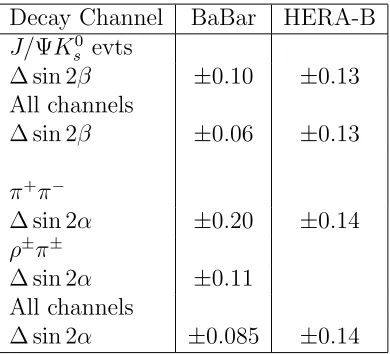
In table 2 is a comparison of the statistical precision that BaBar (and BELLE) and HERA-B
claim can be achieved in measuring sin 2αand sin 2βfor one year’s running at design luminosity.
The two experiments are comparable in theB0 →
J/ΨK0
s channel, but there are other channels
that BaBar can use, because of the clean event environment, to extract the angle α. For
measuring sin 2β at first glance the two experiments are again comparable, but the figures
quoted in the table are for zero background. HERA-B will have a background in B0 →
π+ π−
channel and the quoted figures need to be modified by a factor q1 +B/S where B/S is the
ratio of background to signal. It is thought that a value ofB/S <1 can be achieved [17].
Decay Channel BaBar HERA-B
J/ΨK0 s evts
∆ sin 2β ±0.10 ±0.13
All channels
∆ sin 2β ±0.06 ±0.13
π+ π−
∆ sin 2α ±0.20 ±0.14
ρ±π±
∆ sin 2α ±0.11
All channels
∆ sin 2α ±0.085 ±0.14
Table 2: A comparison of the experimental accuracy of the BaBar and HERA-B experiments
Table 3 reviews the accuracy that the experiments at hadron colliders hope to achieve from
107 seconds running. Besides the accuracy on sin(2α) and sin(2β), the measurement precision
and upper limit of γ and xs (comparable to x in the Bd system) are listed, which need the
Bs mesons to be detected and tagged. The figures show that the dedicated experiment at the
LHC, LHC-B, has by far the best reach in measuring the parameters of CP violation. It is also worth noting that the performance of the Tevatron general purpose detectors are comparable
to result expected from HERA-B and thus the e+
e− B factories. (It should be noted though
the clean experimental environment in e+e− allows them to make a more complete study of
rare B-decays.)
CDF/D0 HERA-B ATLAS/CMS LHC-B BTeV
∆ sin(2α) ∼0.10 ∼0.14 0.10/0.07 0.039 0.1
∆ sin(2β) ∼0.10 ∼0.13 0.02/0.07 0.023 0.042
∆γ 6−16◦
xs ≤17 ≤34 ≤55 ≤30
Table 3: A comparison of the experimental accuracy and reach of the experiments at hadron
facilities. All but BTeV data taken from ref. [18]. BTeV limits from their EoI [16].
5
Conclusions
There is a strong program of future experiments planning to study CP violation in the B
generation experiments are already being planned to extend the measurement of CP violation. The experiments will over constrain the unitarity triangle and perhaps indicate new physics beyond the Standard Model.
References
[1] M. Kobayashi and T. Maskawa, Prog. Theor. Phys. 49 (1973) 652. [2] L. Wolfenstein, Phys. Rev. Lett. 51 (1983) 1945.
[3] J. L. Rosner, ‘The Cabibbo-Kobayashi-Maskawa Matrix’, inB Decays (World Scientific), ed. S. Stone. [4] Y. Nir and H. R. Quinn, ‘Theory of CP Violation in B Decays’, in B Decays (World Scientific), ed.
S. Stone.
[5] I. Dunietz, ‘CP Violation with Additional B Decays’, inB Decays (World Scientific), ed. S. Stone. [6] BELLE Collab., M. T. Cheng et al., Technical Design Report, KEK-Report 95-1.
[7] BaBar Collab., D. Boutigny et al., Technical Design Report, SLAC-R-95-457. [8] HERA-B Collab., E. Hartouni et al., Technical Design Report, DESY-PRC-95/01.
[9] CDF Collab., R. Blair et al., The CDF II Detector Technical Design Report, FERMILAB-Pub-96/390-E. [10] D0 Collab., The D0 Upgrade: The Detector and its Physics, Fermilab Pub-96/357-E.
[11] ATLAS Collab., W. W. Armstrong et al., ATLAS Technical Proposal, CERN/LHCC/94-43. [12] CMS Collab., G. L. Bayatian et al., CMS Technical Proposal, CERN/LHCC/94-38.
[13] I. Vichou, ‘Physics with the ATLAS dtector at LHC’, to appear in these proceedings;
I. Efthymiopouos, ‘Overview of the ATLAS Detector at LHC’, to appear in these proceedings; G. Snow, ‘CMS General Overview and Physics Performance’, to appear in these proceedings; R. Ribeiro, ‘The Tracking System of CMS’, to appear in these proceedings;
D. Barney, ‘The CMS Crystal Calorimeter’, to appear in these proceedings. [14] T. Sj¨ostrand, Computer Physics Commun. 39 (1986) 347;
H.-U. Bengtsson and T. Sj¨ostrand, Computer Physics Commun. 46 (1987) 43. [15] LHC-B Collab., K. Kirsebom et al., LHC-B Letter of Intent, CERN/LHCC 95-5.
[16] BTeV Collab.,A. Santoro et al., BTeV: An Expression of Interest for a Heavy Quark Program at C0, BTeV-pub-97/2
![Figure 9: Production angle of B vs. angle ofB in the laboratory (in units of rad.) at LHCcalculated using the the PYTHIA Monte Carlo generator [14].](https://thumb-us.123doks.com/thumbv2/123dok_us/8047880.1340568/8.612.207.376.497.661/figure-production-laboratory-lhccalculated-pythia-monte-carlo-generator.webp)