Available online:
http://edupediapublications.org/journals/index.php/IJR/
P a g e | 645
Smart Aquaponics System: Design and Implementation
using Arduino Microcontroller
C. K. Cheong, A. M. K. Iskandar, A. S. Azhar,
*W. A. F. W. Othman
School of Electrical & Electronic Engineering, Universiti Sains Malaysia, Malaysia
*
Corresponding author | email:
[email protected]
Abstract:
This paper presents a low-cost design of smart aquaponics system. Aquaponics is a combination of aquaculture, which is growing fish and other aquatic animals, and hydroponics which is growing plants without soil. Aquaponics uses these two in a symbiotic combination in which plants are fed the aquatic animals' discharge or waste. In this work, Arduino microcontroller has been used to control the inputs from several sensors. Based on the sensory input, the Arduino will then control the output to motors. The cost of building the system was not exceeded USD100. The fabricated smart aquaponics system were tested, all functionality of the system were working as intended.
Keywords
Smart system; aquaponics; hydroponics; Arduino; low cost; mechatronics system
1.
Introduction
Aquaponic system is a bio–integrated system that re-circulates water from fish tanks through hydroponics systems to produce high value horticultural crops (Nelson 2007). In other words, ammonia from the effluent produced by the fish will undergo nitrification process in which it will break down to form nitrite (NO2‐) and then the nitrite (NO2‐) is converted to nitrate (NO3‐). This water that contains nitrate is then fed to the hydroponics system and it will act as fertilizer for plants. Finally, the treated water (which is nitrate – free) will flow back to the fish tank (Nelson 2008).
Aquaponic system is greatly useful in maintaining environment sustainability. This system can reduce water consumption compared to traditional farming. Water is lost due to evaporation and transpiration of plant in this system. Thus, water in the fish tank is only replaced with fresh water at 5% to 10% of recirculation water volume daily which is about 80 to 90 percent less water used in traditional farming. Besides that, unlike traditional farming, this system
does not use any chemical and synthetic pesticides, herbicides and fertilizers in growing the crops. This will significantly reduce the harm to the nature (Nelson 2007).
Increasing use of resource and pollution caused by agricultural and aquaculture has incurred high burden to the environment. Untreated water containing uneaten feed and fish faeces which are highly concentrated with nitrogen waste (for example ammonia and nitrites) from the aquaculture can deteriorate the water quality (Anynomous 2009). This situation leads to eutrophication, bloom of phytoplankton in the water body which will harms marine lives by depleting oxygen in the water (Naylor 2000).
Besides, use of chemical fertilizers in the agriculture that consists of metal like aluminium and other ions like sulphate ion, O4S-2 (or SO4-2) and bicarbonate ion, HCO3- alters the pH value and create toxicity in the water (Collins 1996). Water consumption in agriculture is tremendous. 69% of the world’s freshwater withdrawals are committed to agriculture. The industrial sector accounts for 19% while only 12% of water withdrawals are destined for households and municipal use (Schlosser et al. 2014). Hence, an integrated system of agriculture and aquaculture which is known as aquaponics system was introduced to reuse the water and reduce or even avoid the use of chemical fertilizers.
Furthermore, a short introductory video of this work has been uploaded to the YouTube with the link: http://y2u.be/tlcMQ9qP0xU.
2.
Materials & Methods
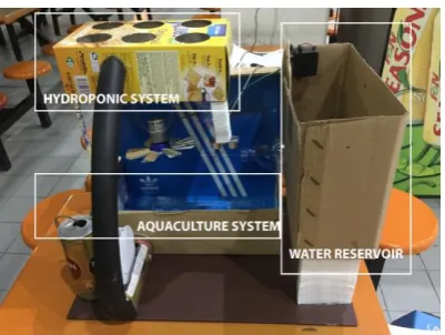
Figure 1 shows the prototype of the proposed system. It is divided into three parts which are:
1. Hydroponics subsystem
2. Fish tanks or Aquaculture subsystem 3. Water reservoir.
Available online:
http://edupediapublications.org/journals/index.php/IJR/
P a g e | 646 aquaculture subsystem, a DC motor is installed
which acts as pump motor that pump water from the fish tank to the grow bed in the hydroponics system. It will operate according to the different durations of on and off state of the motor which is pre-programmed by the Arduino Mega.
Two sensors are implemented in the aquaculture subsystem which is ultrasonic sensor and temperature sensor. The temperature sensor and ultrasonic sensor will detect the temperature of the water and the water level in the fish tank respectively. If the temperature is too high and exceeds the predefined temperature in the Arduino code, the DC motor which acts as the fan will turn on until the temperature falls below the predefined temperature.
Besides, if the water level is low, the servo motor will rotate to open the gate of reservoir. At the same time, the buzzer will sound with different pulse that varies with the water level and the pump motor will be turned off. After the water level return to high level, the gate will be closed, and the buzzer will stop sounding and lastly the pump will continue its operation that is turn on and off alternatively.
3.
System Design
3.1. User Input and Display
In this work, Arduino Mega 2560 microcontroller is adopted as the brain for the proposed system. It is a microcontroller board based on ATmega 2560. It has 54 digital input/output pins (of which 15 can be used as PWM outputs), 16 analog inputs, 4 UARTs (hardware serial ports), a 16 MHz crystal oscillator, a USB connection, a power jack, an ICSP header, and a reset button are available on this board (Arduino, 2017). Arduino microcontroller has proven its reliability and attracted many researchers. Some examples of recent works in the field of robotics which are utilizing Arduino microcontroller includes
the work of Mustapa et al. (2018), Ahmad et al. (2015), Sani et al. (2012) and Faizal et al. (2012).
Figure 2 depicts the control panel of the proposed aquaponics system. When the system is turned on, the LCD display will also turn on and first it will display “LOADING”; while the servo motor will rotate and return to 0° position to close the gate of the water reservoir. After the gate is closed, the LCD display will be cleared, and it shows “AQUAPONICS SYSTEM ON !!” which blinks three times. At this moment, the whole system will turn on and start its operations. Then, the LCD display will be cleared again and shows “PLEASE SELECT A BUTTON” to allow the users to choose one of three buttons to select the predefined menu. These three buttons are interfaced with the Arduino Mega. At any time, only one button can be selected, and the user can switch between any three buttons.
3.1.1.LED & Buzzer
Three Red LEDs and three Green LEDs are implemented in this system (as shown in Fig. 2). Each of the red and green pair LEDs acts as indicators for each of the operations or states of fan motor, pump motor and reservoir gate. If the motor is turned on or gate is opened, each of the respective green LED will light up while red LED will switch off. On the other hand, each red LED will only turn on and green LED is switched off if its respective motor is not rotating or the gate is closed.
A buzzer is used as the audio output of the system to alert the user about the low water level. This buzzer will produce pulses at 1000Hz that its beats per second (BPS) varies according to eq. 1 below, with the depth of water level when its level is low (more than 7.00 cm from the ultrasonic sensor to the water level).
Beats per second (BPS) = 2 × duration of pulse produced
(1) Figure 2: Control Panel of Aquaponic System
Available online:
http://edupediapublications.org/journals/index.php/IJR/
P a g e | 647 where x = 100 × distance of water surface to the
ultrasonic sensor
When the water level decreased from 5.00 cm to 7.00 cm from the ultrasonic sensor to the water level, the buzzer will be triggered by sounding a beat every 80ms and increases to 400ms when the separation of water level to the ultrasonic sensor is at 13.00 cm or higher (Table 1). Directly operate the buzzer through the digital I/O pin of the Arduino will damage the pin. Hence, a BC 547 NPN transistors is used as a switch that also amplify the signals received from the Arduino Mega (as shows in Fig. 3).
3.1.2.Hydroponics subsystem
Plants are grown in this part where their roots are supported by inert medium such as peat moss, perlite and so on. Ebb and flow technique is applied with the help of DC motor that act as a pump (Fig. 4). During the flooding period (pump is turned on), nutrient- rich water will flow through the roots of the plants which causes stale oxygen – depleted air to be driven out from the roots and the plant will absorb nutrients from the water. Then the water will flow
back to the fish tank with the aid of gravity. When the pump is turned off, fresh air is then drawn to the roots again to ensure robust growth of the root during drainage period (Jones 2016).
The operation of the pump motor is controlled by the Arduino Mega. It is set to turn on for 2 minutes and off for 1 minutes and 30 seconds. It will turn on and off alternately. However, when the low water level is detected by the water level sensor, the motor will switch off until the water is filled back to high water level. To drive this pump motor, a quadruple H-bridge, L293D is used since the Arduino Mega is unable to supply this large amount the current through its digital I / O pin (Fig. 5).
3.1.3.Aquaponics subsystem
Fish farming is done in this part of the system. Two sensors are implemented in this subsystem which is ultrasonic sensor (Fig. 6) and temperature sensor, DS18B20 (Fig. 7). In this project, four water levels are predefined which are:
• High water level (5.00 cm from water level to the sensor)
• Normal water level (5.00 cm to 7.00 cm from water level to the sensor)
• Low water level (7.00 cm to 13.00 cm from water level to the sensor)
• Critical low water level (13.00 cm or more from the water level to the sensor)
If the water exceeds the maximum water level, there is a pipe to allow the excess water to be drained back to water reservoir (Nedelkovski 2015).
Besides, the temperature sensor used is a digital sensor, in which commands are sent to the DS18B20 (Maxim Integrated, 2015). This temperature sensor is immersed in the water of the aquaponics subsystem to obtain the temperature of the water. This is important as different fish species has different ambient temperature for their optimum growth (Walberg 2011).
For the temperature of the water in tank, if the temperature is larger than 33°C, another DC motor Figure 3: Circuit design of LED indicator system and
buzzer amplifier.
Table 1: Beats per second produced by the buzzer with its respective distance from water surface to ultrasonic sensor.
Distance of water surface to
the ultrasonic sensor, cm
Duration of pulse produced,
ms
Beats per
second, s-1
5.0 200 2.50
6.0 150 3.34
7.0 120 4.17
8.0 100 5.05
9.0 83 6.06
10.0 70 7.19
11.0 58 8.62
12.0 49 10.30
11.0 40 12.50
Available online:
http://edupediapublications.org/journals/index.php/IJR/
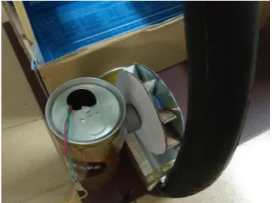
P a g e | 648 which acts as fan mounted on top of the fish tank
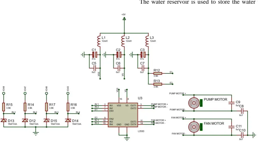
will turn on to improve aeration and reduce the temperature (Fig. 8). This fan motor will only turn off when the temperature falls below 33°C. However, the operation of this fan motor is independent of the water level of the fish tank. Like the pump motor, it is also driven by L293D (Fig. 5).
Available online:
http://edupediapublications.org/journals/index.php/IJR/
P a g e | 649 sensor and temperature sensor used in this work.
3.1.4.Water reservoir
The water reservoir is used to store the water to
Figure 5: Circuit design for pump motor and fan motor suing L293D as motor driver and LC circuit as noise suppressor
Figure 6: Ultrasonic sensor mounted above the fish tank
Figure 7: Temperature sensor is used to measure the water
temperature
Figure 8: DC motor as fan to increase aeration of fish tank
Available online:
http://edupediapublications.org/journals/index.php/IJR/
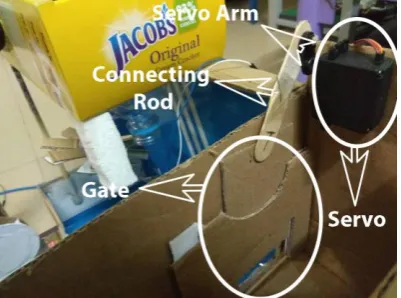
P a g e | 650 be drained into the fish tank when water level in the
fish tank reached low level. There is a gate that controls the flow of water and it is actuated by the servo motor by using the crank slider mechanism (Fig. 10). The servo’s arm will act as the crank while
a connecting rod is attached to the gate.
This will convert rotary motion to linear motion. When the gate is closed, the arm of the servo motor will be at 0° (default position). If low water level is detected, the microcontroller will send signal to the servo motor so that it will rotate 180° anticlockwise to open the gate and the buzzer will turn on and pump water will turn off. If normal water level is detected, the servo motor will rotate 180° clockwise to close the gate. The buzzer now will switch off and the pump motor will continue its normal routine.
Figure 11 shows the circuit design for the servo motor.
3.1.5.Partial Components list
Table 2 shows list of components used in this work and its functionality. Servo motor is used to control the opening gate of reservoir. H-bridge motor driver is used to connect between the motor and microcontroller. H-bridge motor driver also can protect the microcontroller from current surge and electrostatic discharge from the motor to the microcontroller.
4.
EVALUATION
Output Display
LCD display is implemented on this system to display a welcoming message during start up, current water level and temperature of water in the fish tank, the operations of fan and pump motor, the durations of the each of the operations (On or Off) of water pump motor as well as the states of the gate of the water reservoir in three user–selectable menus.
LEDs (three green and red pairs) are used to show the status of the water reservoir’s gate (Open or Close), the operations (On or Off) of the water pump and fan.
Audio Output Device
Buzzer is able to produce pulses with different beats per second that varies according to the different depth of water in the fish tank.
High volume of the sound can be generated with the use of the BJT transistor.
Manual User Input
Three push buttons are available for the user to change the LCD display based on the button that is pressed.
Automatic Sensors
Ultrasonic sensor will detect the water level of the fish tank by recording the duration of echo pin to turn from LOW to HIGH and calculation of distance is performed by the Arduino Mega based on the duration recorded.
Temperature sensor, DS18B20 will monitor and report the temperature of water in the fish tank. A good understanding of using this digital thermometer is required by looking up the datasheet.
Actuator and Mechanism
Crank slider mechanism is applied to control the opening of the gate of reservoir with the aid of servo motor.
Two DC motor are used to produce rotational motion for the fan and water pump.
Logic, Processing and Control
All the programmed logics are controlled by the Arduino Mega.
Closed-loop feedback control schemes (sensors, Mega, motor or servo control and buzzer) are used to determine and control the correct output in terms of motion and sound.
Some calculations are performed by the Arduino Mega to generate different number beats per second by the buzzer and the duration to operate the pump Figure 11: Circuit design for the servo motor
Available online:
http://edupediapublications.org/journals/index.php/IJR/
P a g e | 651 motor as well as the water level distance from the
ultrasonic sensor.
NOT gates are connected to each of the red and green LEDs pairs so that red and green LEDs for each pair have different output (only one will on while the other is in off state).
All the functioning elements in these six categories are working as designed and repeatable. Overall, the designed aquaponics system meets the requirements that set for each functionality category.
5.
DISCUSSION
Team management
Time and work planning and management
Realizing the difficulty and complication that the project could cause, an early start promised us an ample time to build a high-quality project. With the existence of team-working between the team members, works were distributed among the members according to their ability, in which eventually boosted up the speed of finishing the project.
Electronics
Understand the effect of interference between different components
Initially, the system sometimes crashed, and the LCD showed unwanted characters for unknown reason. After researching from the internet, we found that this problem was caused by the noise interference of the motor that is produced during the start of the motor in which large current is needed. Hence, we implemented LC (inductor in series and capacitor in parallel) circuits that act as low pass filter as close as possible between the input power supply of the L293D IC and the ground. Besides, small (0.1µF) ceramic capacitors were put between the motor and servo terminals. Lastly, decoupling capacitors were placed across the SN7404 IC and LCD display to overcome the voltage dips and spikes. Without changing any code, the system functioned properly.
Understand the precautions when using the microcontroller
During development of this project,
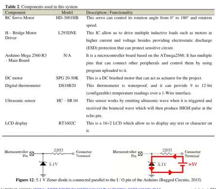
Table 2: Components used in this system
Component Model Description | Functionality
RC Servo Motor HD-3001HB This servo can control its rotation angle from 0° to 180° and rotation
speed.
H – Bridge Motor Driver
L293DNE This IC allow us to drive multiple inductive loads such as motors at
higher current and voltage besides providing electrostatic discharge
(ESD) protection that can protect sensitive circuit.
Arduino Mega 2560 R3 – Main Board
N/A It is a microcontroller board based on the ATmega2560. It has multiple
pins that can connect other peripherals and control them by using
program uploaded to it.
DC motor SPG 20-50K This is a DC brushed motor that can act as actuator for the project.
Digital thermometer DS18B20 This thermometer is waterproof, and it can provide 9 to 12-bit
(configurable) temperature readings over a 1-Wire interface.
Ultrasonic sensor HC – SR 04 This sensor works by emitting ultrasonic wave when it is triggered and
received the bounced wave which will then produce HIGH pulse at the
echo pin.
LCD display RT1602C This is a 16×2 LCD which allow us to display any text or character on
it.
Available online:
http://edupediapublications.org/journals/index.php/IJR/
P a g e | 652 misconnection could be occurred which would cause
overvoltage or over current condition to be happened. This would lead to permanent damage to the microcontroller board. In averting this situation, we found a solution via the internet by connecting the microcontroller I/O pins with resistors in series and 5.1 V Zener diodes in reverse bias in parallel (as shown in Fig. 12). The resistor will limit the current during the over current while the Zener diode will allow the current to safely flow through it, to the ground and back to the overvoltage source during overvoltage (Rugged Circuits 2015).
Code
Check the compatibility of the microcontroller with the library in the coding
The microcontroller is the core of our project. Hence, suitability of the microcontroller is important in determining the functions of the system. For example, in our project, the usage of the code, tone will interfere the PWM outputs of other pins as both outputs use the same timer (Arduino 2017). This situation could hinder the use of servo motor which is a very important feature of our system. To solve this problem, Arduino Mega was selected as both outputs use different timer.
Understand the library before use it
This problem arose when using the temperature sensor, DS18B20 library. When requesting the temperature using this library, it will cause 750ms delay during the operation (Burton 2017). This can cause the program to run inaccurately and ineffectively. Thus, we had to look up the datasheet of the temperature and understand how to interface between Arduino Mega with the sensor and rewrote a new program without using the library. As a result, the outputs of the system were not affected by the delay caused during requesting the temperature.
6.
CONCLUSION
In this work, we have designed a smart aquaponics system to automatically watering the plant, and maintaining the temperature of water using a mechatronics system approach. This mechatronics system is consisting of ultra sonic sensor, temperature sensor, an Arduino microcontroller, several motors as the actuator and the mechanical system.
We have fulfilled the theme that is 3R as we are using recycled materials to produce the prototype. Old CDs were used as the propeller for fan connecting it to a DC motor as to maintain the
temperature of the water. Unused boxes are reused to make the main body of the prototype.
7.
REFERENCES
1. Ahmad MF, Alhady SSN, Kaharuddin S, et al
(2015). “Visual based sensor cart follower for wheelchair by using microcontroller”. In. Proc. 2015 IEEE International Conference on Control System, Computing and Engineering (ICCSCE), IEEE, pp. 123-128
2. Anonymous (2009). “Water Usage in Recirculating Aquaculture/Aquaponic Systems”. (Fact Sheet August 2009). Retrieved from Food
& Water Watch:
http://www.lanikaifarms.com/Recirculating%20 Aquaculture%20Systems%20(RAS).pdf (last accessed: 2018-Oct)
3. Arduino (2017). “Advanced I/O: tone()”. Retrieved from Arduino Web site: https://www.arduino.cc/reference/en/language/fu nctions/advanced-io/tone/ (last accessed: 2018-Oct)
4. Burton M (2017). “Arduino Temperature Control Library”. Retrieved from GitHub Inc. Web Site:
https://github.com/milesburton/Arduino-Temperature-Control-Library (last accessed: 2018-Oct)
5. Collins R, Jenkins A. (1996). “The impact of agricultural land use on stream chemistry in the Middle Hills of the Himalayas, Nepal”. Journal of Hydrology, 185, pp. 71-86.
6. Faizal MIN, Othman WAFW, Syed Hassan SSNA (2015). “Development of pole-like tree climbing robot”, In. Proc. 2015 IEEE International Conference on Control System, Computing and Engineering (ICCSCE), IEEE, pp. 224-229 7. Jones JB Jr (2016). “Hydroponics: A Practical
Guide for the Soilless Grower”. Florida: CRC Press.
8. Maxim Integrated (2015). Programmable Resolution 1-Wire Digital Thermometer. Retrieved from Maxim Integrated Web Site: https://datasheets.maximintegrated.com/en/ds/D S18B20.pdf (last accessed: 2018-Oct)
9. Mustapa MA, Othman WAFW, Abu Bakar E et al. (2018). “Development of Pole-Like Tree Spiral Climbing Robot”. In: Hassan M. (eds) Intelligent Manufacturing & Mechatronics. Lecture Notes in Mechanical Engineering. Springer, Singapore, pp. 285-293
10. Naylor RL, Goldburg RJ, Primavera RJ et al.
(2000). “Effect of aquaculture on world fish supplies”. NATURE, 405, pp. 1017 - 1024. 11. Nedelkovski D (2014). “Ultrasonic Sensor
Available online:
http://edupediapublications.org/journals/index.php/IJR/
P a g e | 653 Mechatronics. Retrieved from How to
Mechatronics Web Site:
http://howtomechatronics.com/tutorials/arduino/ ultrasonic-sensor-hc-sr04/ (last accessed: 2018-Oct)
12. Nelson RL (2008). “Aquaponic equipment the bio filter”. Aquaponic Journal, 48(2).
13. Nelson RL (2007). “Ten aquaponic systems around the world”. Aquaponics Journal, 46, pp. 1-8.
14. Rugged Circuits (2015). “10 Ways to Destroy An Arduino”. Retrieved from Rugged Circuits Web Site: https://www.rugged-circuits.com/10-ways-to-destroy-an-arduino/ (last accessed: 2018-Oct) 15. Sani NA, Syed SSNA, Othman WAFW, et al.
(2012). “Cordless Cart Follower for Wheelchair User”, Trends in intelligent robotics, automation, and manufacturing, Springer, Berlin, Heidelberg, pp. 252-262
16. Schlosser CA, Strzepek K, Gao X, et. al (2014). “The Future of Global Water Stress: An Integrated Assessment”. Earth's Future, 2(8), pp. 341–36
17. Walberg E (2011). "Effect of Increased Water Temperature on Warm Water Fish Feeding Behavior and Habitat Use," Journal of Undergraduate Research at Minnesota State University, Mankato: Vol. 11, Article 13.
Available at: