IJEDR1603134
International Journal of Engineering Development and Research (www.ijedr.org)822
________________________________________________________________________________________________________Abstract- Static VAR Compensator (SVC) is a power quality apparatus from one of the member of Flexible AC Transmission System (FACTS) device family, which utilizes power electronics to manage the flow of reactive power in the system wherever it is connected. As a result, it is capable to offer fast acting reactive power reimbursement on electrical systems. In other words, static var compensators have their output accustomed to switch over inductive or capacitive current to facilitate control power system constraints such as the bus voltage. Additionally, static var compensators are installed at appropriate points in the electric power system to raise its transfer capability by increasing voltage stability, while under different system conditions keeping the voltage profile smoother. SVCs is be capable of diminish active power oscillations through voltage amplitude modulation. Furthermore, as an automated impedance matching device, they have the further benefit of bringing the system power factor close to unity. This project work deals with the development of a power quality improvement system especially for the voltage profile of the transmission line through Adaptive Nuero Fuzzy regulator based static var compensator. The basic idea for this project work came from the drawbacks of the PI based conventional voltage regulator that employs the voltage error (difference among the measured voltage Vm and the reference voltage Vref) to find out the SVC susceptance BSVC needed to keep the system voltage constant. The Adaptive Nuero Fuzzy regulator based static var compensator has the ability to handle the variation of voltage efficiently under the dual side three phase fault condition to maintain the voltage profile smooth and better for the system in comparison to the conventional PI based voltage SVC.
Index terms:Voltage Stability, Three Phase Transmission system, Voltage Regulation, ANFIS, SVC.
________________________________________________________________________________________________________
1. Introduction
Power Quality in electric network is one of today most concerned area of electrical power system .The power quality has severe economic implication for consumers, utilities and electrical apparatus manufactures. This impact of power quality troubles is increasingly felt by customers, industrial, commercial and even residential. Some of major power quality problems are voltage sag, swell, transients, harmonic and flickers etc. This paper work present for the voltage profile stability in the transmission system. The power electronics device SVC shunt compensation device for the recover voltage quality of system. Power electronic device we refer to FACTS device ststic var compensator used for the power quality improvement and power quality problems like voltage sag or swell in transmission system. SVC is shunt compensation device used for the voltage quality enhancement in transmission system.
2. SVC
There are three common configurations of static var compensators and each will be described below. (i). Thyristor-controlled Reactors with Fixed Capacitors (TCR/FC)
This SVC design having two parallel branches connected on the secondary side of a coupling transformer. One of the branches is uses reactors that are controlled by AC thyristor switches. Additionally, the reactors are connected in delta for three-phase applications. The other branch could either be fixed capacitor banks or shunt filters.
IJEDR1603134
International Journal of Engineering Development and Research (www.ijedr.org)823
Figure 1. Thyrsitor-controlled Reactors with Fixed Capacitors (or Shunt Filters)(ii). Thyristor switched capacitors (TSC)
In this type of static var compensator device, the capacitor banks are linked phase-to-phase, with each section switched by thyristors. Thus, a distinct variation of the reactive power can be attaining but not a continuous alteration similar to that of a TCR. On the other hand, by given that a suitably large number of small sections, the required resolution of reactive power alteration for a single step can be achieved. Synchronization of switching and initial pre-charging of the capacitors limits the transients usually linked with capacitor switching. Generally, the reaction time for symmetrical operation does not exceed 20 ms
Figure 2. Thyristor-switched Capacitors (TSC) .(iii). Thyristor-controlled Reactors and Thyristor switched capacitors (TCR/TSC)
Fundamentally, this is the grouping of TCR and TSC. In this configuration, the control of the static var compensator is depends on measuring the reactive component of load current at the instantaneous of voltage zero. Subsequently, the measured current is used to obtain the firing angle so that the SVC absorbs or injects the amount of reactive power requisite for compensation. However, there is a time interval between the instant of measuring the reactive component (in one half-cycle) and the firing instant (the next half-cycle). This natural delay of its operation mode is one of its major limitations.
3. Voltage profile Improvement System with Adaptive Neuro Fuzzy Controller based Voltage Regulator SVC
This section deals with designing and implementation of proposed Adaptive Neuro Fuzzy controller based voltage regulator SVC Voltage quality improvement system in MATLAB Simulink. In the conventional voltage regulation system regulation in voltage done by PI controller, used for varying susceptance for SVC to maintain the voltage constant during the steady state as well as under transient condition. The job of this PI controller is to control the difference between the measured voltage Vm and reference
voltage VRef and provide the appropriate susceptance in SVC to maintain constant voltage.
3.1 Description of developed Adaptive Neuro Fuzzy controller based voltage Regulation SVC Model
This project basically deals with the replacement of the conventional PI controller based voltage regulator unit with the efficient ANFIS controller based voltage regulator.
IJEDR1603134
International Journal of Engineering Development and Research (www.ijedr.org)824
Distribution Unit Secondary
Voltage
PLL TCS
TCR
Proposed Static Var Compensator Structure
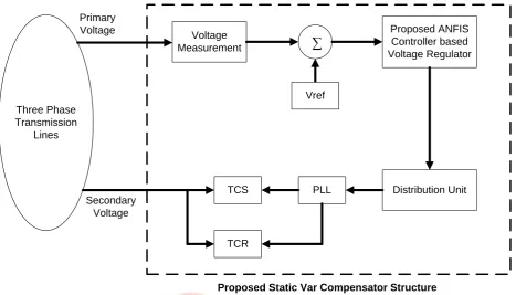
Figure 3. Block diagram representation of Project work.
Similar to the conventional SVC, the proposed SVC system also contains same blocks except the ANFIS controller based voltage regulator. For time being, we first explain the common blocks between the conventional SVC and proposed SVC system in following paragraphs in detail while the detail development of the proposed voltage regulator unit will be discussed in the next subsection.
IJEDR1603134
International Journal of Engineering Development and Research (www.ijedr.org)825
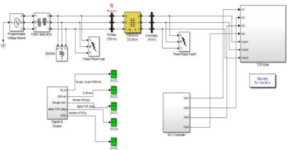
Figure 5. Simulation Diagram of Project Work.The Proposed SVC control system consists of the following four main modules:
Measurement System determines the positive-sequence primary voltage. This system uses discrete Fourier computation technique to estimate essential voltage over a one-cycle running average window. The voltage measurement unit is driven by a phase-locked loop (PLL) to take into account change in of system frequency.
In the conventional SVC, a Voltage Regulator is present which uses a PI regulator to regulate primary voltage at the reference voltage (1.0 pu specify in the SVC Controller block menu). A voltage droop is incorporated in the voltage regulation to obtain a V-I characteristic with a slope (0.01 pu /100 MVA). Therefore, when the SVC operating point changes from fully capacitive (+300 Mvar) to fully inductive (-100 Mvar) the SVC voltage varies between 1-0.03=0.97 pu and 1+0.01=1.01 pu.
In the proposed SVC system, an ANFIS controller based voltage regulator has been employed to replace the available PI controller and droop control method based voltage regulator of conventional SVC.
i. In conventional SVC the Distribution Unit uses the primary susceptance Bsvc computed by the voltage regulator to determine the TCR firing angle α and the status (on/off) of the three TSC branches. The firing angle α as a function of the TCR susceptance BTCR is executed by a look-up table from the equation
BTCR=
2(π−α)+ sin (2α)
π ..(1)
Where BTCR is the TCR susceptance in pu of rated TCR reactive power (109 Mvar)
ii. Firing Unit consists of three independent subsystems, one for each phase (AB, BC and CA). Each subsystem having a PLL synchronized on line-to-line secondary voltage and a pulse generator for all of the TCR and TSC branches. The pulse generator uses the firing angle α and the TSC status which are coming from the Distribution Unit to generate pulses. The firing of TSC branches can be synchronized (one pulse is sent at positive and negative thyristors at every cycle) or continuous. The synchronized firing mode is usually the preferred method because it reduces harmonics faster.
3.2 Development of Proposed ANFIS Controller based Voltage Regulator
This section presents the development of proposed ANFIS controller based voltage regulator for the SVC system. More specifically the proposed ANFIS controller based voltage regulator uses the measured voltage Vm of the line and the reference
voltage Vref to estimate the SVC susceptance BSVC needed to keep the system voltage constant.The basic idea is to first analyse the
inputs and the output response of the conventional voltage regulator and then correction will be made in accordance with the required voltage stability response. The corrected response for the training of the proposed ANFIS controller based voltage regulator is shown in table-1 below. The length of the actual training data used is 12000 samples, but here we are showing 10 samples out of complete data.
Table 1. ANFIS training data table shows 5 samples
S. No.
ANFIS Input
ANFIS Target Measured Voltage of line
(Vm) in pu
Reference Voltage (Vref) in pu
IJEDR1603134
International Journal of Engineering Development and Research (www.ijedr.org)826
ANFIS controller. The rule base developed for ANFIS controller is as follows1. If (Vm is in1cluster1) and (Vref is in2cluster1) then (B is out1cluster1) (1) 2. If (Vm is in1cluster2) and (Vref is in2cluster2) then (B is out1cluster2) (1)
The above rules indicate that the developed controller has been designed very efficiently with the help only two different rules and hence can provide fast response as compare to the conventional voltage regulator of the SVC system.
(a) Membership function of first input variable Vm
(b) Membership function of second input variable Vref Figure 5. (a) and (b) Membership function plots for input variables
Figure 6. Structure of the developed ANFIS Controller.
4. Simulation Results and Discussion
0.1 0.2 0.3 0.4 0.5 0.6 0.7 0.8 0.9 1
0 0.2 0.4 0.6 0.8 1
Vm
De
gr
ee
o
f m
em
be
rs
hip
in1cluster1 in1cluster2
0.5 0.505 0.51 0.515 0.52 0.525 0.53 0.535 0.54
0 0.2 0.4 0.6 0.8 1
Vref
De
gr
ee
o
f m
em
be
rs
hi
p
IJEDR1603134
International Journal of Engineering Development and Research (www.ijedr.org)827
Both the systems have been tested against the dual side faults generated in the system. The primary side fault has been generated for the .1 sec duration from t= .2 sec to t = .3 sec of time span. While the secondary side fault has been generated for .2 sec duration, but for different time span t = .5 to t = .7 sec. the performance evaluated for the both the systems have been described below:Taking phase AB to ground fault for both the primary and secondary side. The three phase voltage waveform obtained for this case is shown in figure (7).
Figure 7. Phase AB to ground fault effect on the transmission line voltage profile
The above figure clearly indicates that the there are two fault conditions on phase A and phase B on two different time spans. The first fault is occurred here for .1 sec fron t = 0.2 sec to t = 0.3 sec while the second fault is occurred for again .1 sec from t = .5 sec to t = .6sec.
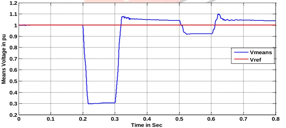
Now the results obtained after restoration of the means voltage for the conventional SVC based system is shown in figure (8).
Figure 8. The line voltage regulation response of conventional SVC system
From the above figure it is clear that, during the fault timing the means voltage dropped to very low values but after the clearance of fault the conventional SVC settles the voltage within the tolerance range of .1 pu, which indicates the 90 percent efficiency of the conventional SVC to recover and provide voltage stability. On the other hand figure (9) shows the voltage stabilization response of the proposed ANFIS controller based SVC system.
0 0.1 0.2 0.3 0.4 0.5 0.6 0.7 0.8
-4 -3 -2 -1 0 1 2 3 4
Time in Sec
P h a s e A B C V o lt a g e i n p u
0 0.1 0.2 0.3 0.4 0.5 0.6 0.7 0.8
0.2 0.3 0.4 0.5 0.6 0.7 0.8 0.9 1 1.1 1.2 M e a n s V o lt a g e in p u
Time in Sec
IJEDR1603134
International Journal of Engineering Development and Research (www.ijedr.org)828
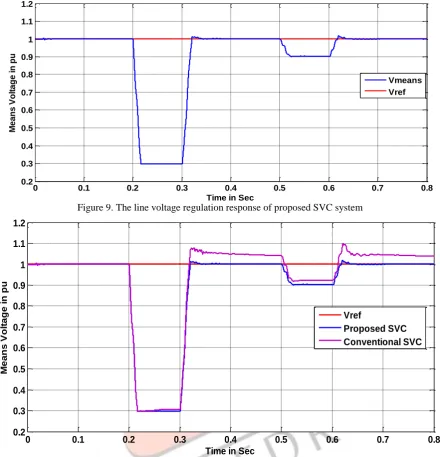
Figure 9. The line voltage regulation response of proposed SVC systemFigure 10. The line voltage regulation response of Conventional SVC and proposed SVC system
The voltage regulation response obtained for the proposed SVC system clearly signifies that the as soon the fault clears the proposed SVC system rapidly stabilizes the line voltage with very high efficiency. The detail comparison of the conventional SVC response and Proposed SVC system response is shown in figure (10).
From the above figure one can easily observe that the proposed ANFIS controller based SVC system is highly efficient in achievinghigh voltage stabilization as compare to the conventional SVC system under the Phase AB to ground fault.
Reference
[1] S. M. H. Hosseini, J. Olamaee and H. Samadzadeh, "Power oscillations damping by Static Var Compensator using an Adaptive Neuro-Fuzzy controller," Electrical and Electronics Engineering (ELECO), 2011 7th International Conference on, Bursa, 2011, pp. I-80-I-84
[2] M. Ginarsa, A. Soeprijanto, M. H. Purnomo, Syafaruddin and T. Hiyama, "Controlling voltage collapse using ANFIS-based composite controller-SVC in power systems," TENCON 2011 - 2011 IEEE Region 10 Conference, Bali, 2011, pp. 74-78 [3] K. L. Lo and M. O. Sadegh, "Systematic method for the design of a full-scale fuzzy PID controller for SVC to control power
system stability," in IEE Proceedings - Generation, Transmission and Distribution, vol. 150, no. 3, pp. 297-304, May 2003. [4] Lak, D. Nazarpour and H. Ghahramani, "Novel methods with Fuzzy Logic and ANFIS controller based SVC for damping
Sub-Synchronous Resonance and low-frequency power oscillation," 20th Iranian Conference on Electrical Engineering
(ICEE2012), Tehran, 2012, pp. 450-455
[5] D. Z. Fang, Yang Xiaodong, T. S. Chung and K. P. Wong, "Adaptive fuzzy-logic SVC damping controller using strategy of oscillation energy descent," in IEEE Transactions on Power Systems, vol. 19, no. 3, pp. 1414-1421, Aug. 2004
[6] Gupta and P. R. Sharma, "Fuzzy based Svc auxiliary controller for damping low frequency oscillations in a power system,"
Confluence 2013: The Next Generation Information Technology Summit (4th International Conference), Noida, 2013, pp.
87-91.
0 0.1 0.2 0.3 0.4 0.5 0.6 0.7 0.8
0.2 0.3 0.4
Time in Sec
0 0.1 0.2 0.3 0.4 0.5 0.6 0.7 0.8
0.2 0.3 0.4 0.5 0.6 0.7 0.8 0.9 1 1.1 1.2
M
e
a
n
s
V
o
lt
a
g
e
i
n
p
u
Time in Sec
Vref
IJEDR1603134
International Journal of Engineering Development and Research (www.ijedr.org)829
compensator (SVC)," SAI Intelligent Systems Conference (IntelliSys), 2015, London, 2015, pp. 507-517.[8] C. M. Valle, A. O. Borges, G. C. Guimaraes and H. R. Azevedo, "Fuzzy logic controller simulating an SVC device in power system transient stability analysis," Power Tech Proceedings, 2001 IEEE Porto, Porto, 2001, pp. 4 pp. vol.4
[9] N. A. Arzeha, M. W. Mustafa and R. Mohamad Idris, "Fuzzy-based Static VAR Compensator controller for damping power system disturbances," Power Engineering and Optimization Conference (PEDCO) Melaka, Malaysia, 2012 Ieee
International, Melaka, 2012, pp. 538-542
[10]S. Khanmohammadi, M. T. Hagh and M. Abapour, "Fuzzy logic based SVC for reactive power compensation and power factor correction," 2007 International Power Engineering Conference (IPEC 2007), Singapore, 2007, pp. 1241-1246.
[11]Kazemi and M. V. Sohrforouzani, "Power system damping using fuzzy controlled FACTS devices," Power System
Technology, 2004. PowerCon 2004. 2004 International Conference on, 2004, pp. 1623-1628 Vol.2
[12]T. Abdelazim and O. P. Malik, "Intelligent SVC control for transient stability enhancement," IEEE Power Engineering
Society General Meeting, 2005, 2005, pp. 1701-1707 Vol. 2.
[13]T. Abdelazim and O. P. Malik, "Intelligent SVC control for transient stability enhancement," IEEE Power Engineering
Society General Meeting, 2005, 2005, pp. 1701-1707 Vol. 2.
[14]S. Khan, R. Meena and S. Bhowmick, "Small signal stability improvement of a single machine infinite bus system using SVC," 2015 Annual IEEE India Conference (INDICON), New Delhi, 2015, pp. 1-5.
[15]Gelen and T. Yalcinoz, "The behaviour of TSR-based SVC and TCR-based SVC installed in an infinite bus system,"
Electrical and Electronics Engineers in Israel, 2008. IEEEI 2008. IEEE 25th Convention of, Eilat, 2008, pp. 120-124.
[16]J. Zhu, D. Hwang and A. Sadjadpour, "Loss reduction from use of new SVC model," Power and Energy Society General
Meeting - Conversion and Delivery of Electrical Energy in the 21st Century, 2008 IEEE, Pittsburgh, PA, 2008, pp. 1-7.
[17]Peiyuan Chen, Zhe Chen and B. Bak-Jensen, "Comparison of steady-state SVC models in load flow calculations,"
Universities Power Engineering Conference, 2008. UPEC 2008. 43rd International, Padova, 2008, pp. 1-5.
[18]R. Grunbaum, M. Halonen and G. Stromberg, "SVC for 69 kV direct grid connection," 2008 IEEE/PES Transmission and
Distribution Conference and Exposition, Chicago, IL, 2008, pp. 1-7.
[19]Baggini, A. (2008). Handbook of Power Quality