Prepared for the U.S. Department of Energy under Contract DE-AC02-09CH11466.
PPPL-
4819
PPPL-
4819
Progress in Developing a High-Availability Advanced Tokamak Pilot Plant
September, 2012
T. Brown, A.E. Costley, R.J. Goldston, L.El-Guebaly, C. Kessel, G.H. Neilson, S. Malang, J.E. Menard, S. Prager, S. Scott, P. Titus,
Full Legal Disclaimer
This report was prepared as an account of work sponsored by an agency of the United States Government. Neither the United States Government nor any agency thereof, nor any of their employees, nor any of their contractors, subcontractors or their employees, makes any warranty, express or implied, or assumes any legal liability or responsibility for the accuracy, completeness, or any third party’s use or the results of such use of any information, apparatus, product, or process disclosed, or represents that its use would not infringe privately owned rights. Reference herein to any specific commercial product, process, or service by trade name, trademark, manufacturer, or otherwise, does not necessarily constitute or imply its endorsement, recommendation, or favoring by the United States Government or any agency thereof or its contractors or subcontractors. The views and opinions of authors expressed herein do not necessarily state or reflect those of the United States Government or any agency thereof.
Trademark Disclaimer
Reference herein to any specific commercial product, process, or service by trade name, trademark, manufacturer, or otherwise, does not necessarily constitute or imply its endorsement, recommendation, or favoring by the United States Government or any agency thereof or its contractors or subcontractors.
PPPL Report Availability
Princeton Plasma Physics Laboratory:
http://www.pppl.gov/techreports.cfm
Office of Scientific and Technical Information (OSTI):
http://www.osti.gov/bridge
Related Links:
U.S. Department of Energy
Office of Scientific and Technical Information Fusion Links
FTP/P7-28: Progress in Developing a High-Availability Advanced Tokamak
Pilot Plant
T. Brown1, A. E. Costley2, R.J. Goldston1, L. El-Guebaly3, C. Kessel1, G.H. Neilson1,S. Malang4, J. E. Menard1, S. Prager1, S. Scott1, P. Titus1, L. Waganer5, M. Zarnstorff1
1) Princeton Plasma Physics Laboratory, Princeton, NJ, USA
2) Consultant, former Head of Diagnostics in ITER, Henley on Thames, UK 3) University of Wisconsin, Madison, WI, USA
4) Consultant, Fusion Nuclear Technology Consulting, Linkenheim, Germany 5) Consultant, formerly with The Boeing Company, St. Louis, MO, USA Email-contact of main author: [email protected]
Abstract - A fusion pilot plant study was initiated to clarify the development needs in moving from ITER to a first of a kind fusion power plant. The mission of the pilot plant was set to encompass component test and fusion nuclear science missions yet produce net electricity with high availability in a device designed to be prototypical of the commercial device. The objective of the study was to evaluate three different magnetic configuration options, the advanced tokamak (AT), spherical tokamak (ST) and compact stellarator (CS) in an effort to establish component characteristics, maintenance features and the general arrangement of each candidate device. With the move to look beyond ITER the fusion community is now beginning to embark on DEMO reactor studies with an emphasis on defining configuration arrangements that can meet a high availability goal. This paper reviews the AT pilot plant design, detailing the selected maintenance approach, the device arrangement and sizing of the in-vessel components. Details of interfacing auxiliary systems and services that impact the ability to achieve high availability operations will also be discussed.
1. Introduction
The pilot plant design study initiated to clarify the development needs in moving from ITER to a first of a kind fusion power plant has been addressed in recent papers [1-2] providing background details, assessment of research needs and preliminary snapshots of design features developed for candidate options: advanced tokamak (AT), spherical tokamak (ST) and compact stellarator (CS). Developing a device configuration that allows operation with high availability involves a major departure in the design approach of present experimental devices and from the design currently being developed for ITER. This paper focuses on the AT design.
The AT configuration incorporates the advanced tokamak pilot plant physics parameters developed around a double-null divertor, departing from the ITER single-null plasma condition. An overarching goal of the configuration effort was to develop design concepts that improved access and fostered maintenance simplification to increase availability. Concepts that increased the device size were allowed if maintenance and operation availability was enhanced and the size increase was deemed reasonable. Recognizing that a fusion device will be surrounded by auxiliary equipment and services that can interfere with the maintenance of in-vessel components, designs which minimized conflicts with auxiliary equipment interactions were favored. Developing design concepts for the fusion core independent of developing some level
of definition and direction planned for auxiliary equipment, services and the facility can result in choosing a design approach for the device core that leads to erroneous conclusions; therefore an effort was made to broaden the AT configuration design to include all configuration driving systems. ITER can provide a great deal of direct engineering and manufacturing experience that can be used in developing the machine design, especially with regard to base components that are not part of the planned experimental mission of the project. This would include the superconducting TF and PF coils, cryostat and thermal shield, the vacuum vessel, auxiliary systems and supporting services. The thrust of an AT design is to build on the ITER experience, incorporating anticipated technology improvements and develop a vacuum vessel / superconductor magnet system topology which optimizes in-vessel component maintenance.
2.0 Configuration Development Background
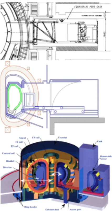
Design studies promoting maintenance enhancements have been undertaken within the fusion community over a long period of time [3-7]. Some of the most recent configurations are shown in Figure 1 incorporating both horizontal and vertical maintenance approaches. Selecting the maintenance approach is not straightforward. Horizontal maintenance with a subdivided set of in-vessel sector components equal to the number of TF coils, as illustrated in the sixteen sector configuration of Figure 1a, 1b and 1d, minimizes the number of replacement modules, locates a minimum set of coolant services within the maintenance port and based on proponents availability studies provides the highest availability among the different maintenance options. However, incorporating equal number of in-vessel sector modules as the number of TF coils has some negative effects. One impact is the need to expand the size of the TF coil to allow space to remove a full plasma chamber sector module. This will result in increased machine cost and an increase in the TF winding length, potentially reaching limits on pumping power for CICC superconducting coils. Other negative aspects of horizontal maintenance with the number of
plasma chamber replacement sectors equal to the number of TF coils is the excessive size and weight of the chamber sector and the proposed maintenance space that is added circumferentially around the device to service the sector modules. The large size of the plasma chamber device complicate the cask design, hot cell details and adds difficulty in handling and aligning the sectors within the vacuum vessel itself. Horizontal maintenance options have been further modified to increase the number of replacement sector components to a value larger than the number of TF coils. This approach is exemplified in a four-port maintenance scheme shown in Figure 1b. Here the TF coils are enlarged but less than required for the case with equal number of sectors as TF coils. Sectors are moved within the plasma chamber in a toroidal direction to an extraction port; generally at four port locations. Coolant tube connections are made from the outside using internal coolant tube cutting/welding tools and sector alignment is accomplished at the base of the modules. This altered horizontal maintenance option reduces the size of the sector module and removes the need of the full toroidal maintenance corridor surrounding the device; but in making these changes a compromise is made to the availability advantage offered by the original equal sector horizontal maintenance approach.
Is it even practical to configure a maintenance corridor around a tokamak device? A large number of auxiliary equipment items, services and diagnostic systems interface with the fusion device core. Figure 2 illustrates examples of horizontal port interfaces, ranging from the 40 ton ITER shield plug to the 130 ton JA Demo-CREST outer shield and finally to the 250 ton JA CREST blanket and divertor system. Allowing horizontal space for sector maintenance competes for space with other systems.
A study was undertaken by A. E. Costley to investigate diagnostic aspects dealing with the three pilot plant options [8]. To minimize the impact of the diagnostics on the machine design, it was assumed that measurements are required for
control and performance optimization functions only and that additional dedicated systems to support a detailed scientific program are not included. Cautiously optimistic assumptions were made about diagnostic developments that are on-going in the diagnostic field, especially in the preparations for ITER, and which should be available by the time the detailed design of the pilot plant will be undertaken. It was concluded that the AT options will require ~ 27 diagnostic
systems installed in 4 upper, 2 mid-plane, and 4 lower ports, and probably some systems integrated in the divertor tiles and structures. Close coupling to the plasma for heating, current drive and other systems will favor keeping the components close to the device. In existing fusion experimental device, the device itself is often obscured from view by all the external interfacing components. A maintenance approach that provides the least interaction with auxiliary equipment is preferred.
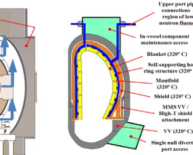
The horizontal port option that restricts the port maintenance to a few large midplane ports takes away the need for a maintenance corridor but competition with auxiliary systems still remains. Restricting the maintenance to a few horizontal ports requires plasma chamber toroidal movement and adds outside piping interfaces, which brings into play some of the features called for in the vertical maintenance approach. The EU multi-module segment (MMS) [4] concept shown in Figure 1c is a vertical maintenance approach incorporating large sectors (greater than the number of TF coils) that are transported within the plasma chamber by maintenance tools inserted from the divertor ports and supported by divertor rails. 2 – 3 upper ports need to be opened to extract/insert the MMS. Coolant tubes are collected in the upper region and internal coolant tube cutting/welding tools are used to service the pipes; vertical sector alignment is also provided at the top. Having the ability to incorporate vertical alignment methods is a positive attribute of the vertical maintenance approach as most if not all current fusion devices use vertical assembly / alignment processes during initial construction.
3.0 AT maintenance configuration down selection
One area of concern in looking at a vertical port maintenance approach for a double-null divertor condition was the ability to develop a PF coil arrangement that provided the space for large vertical openings to extract the plasma modules as well as provide the proper magnetic fields to shape the plasma. Space requirements for both horizontal and vertical maintenance approaches were developed and successful equilibrium calculations were made for both options with slightly lower PF currents coming from the vertical access case.
The debate between horizontal and vertical maintenance approaches is not new and the rational for selecting one approach over another has been documented, even though no design study has been carried out in sufficient detail to fully qualify the results. Given the concerns of a horizontal maintenance approach discussed, a vertical maintenance approach was selected for the AT pilot plant option for further development following a somewhat different path than the approach envisioned by the European MMS concept.
4.0 Details of the AT Vertical Maintenance approach
The AT vertical maintenance scheme developed subdivides the plasma components into inboard and outboard segments similar to the EU design but locates them in an expanded vacuum vessel. A semi-permanent inboard shield forms a strongback for supporting disruption loads, providing shielding for gaps between sectors and is used as the alignment system for the plasma components. Instead of supporting the internal blanket/shield modules from the vacuum vessel a lower base platform is included that also serves as a coolant plenum to service the FW/blanket modules. Figure 3 shows the basic comparison between the EU MMS and PPPL AT design
Figure 3: Concept comparison between EU MMS and PPPL vertical maintenance option concepts. In-vessel segmentation for the AT vertical maintenance concept was developed for a twelve TF coil magnet system, sized by ripple requirements. Figure 4 highlights the different component types that make up the blanket / shield system. There are 12 components of each type; outboard blanket/shield module, blanket/shield post, inboard blanket port module and inboard shield modules. The divertor system is sub-divided into 24 upper and lower unites, sized to allow them to be retracted independent from the blanket modules.
Figure 4: In-vessel segmentation scheme
The isometric views shown in Figure 5 illustrate the device core base components which are expected to operate for the lifetime of the pilot plant. This includes the superconducting magnets, the magnet support system, cryostat, semi-permanent shield, machine base support and piping system. Incorporating a
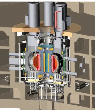
separate interior shield structure can potentially affect the device size but any small increase in major radius is offset by the simplification in the alignment of the blanket/shield modules, supporting components against disruption loads and adding gap shielding of adjacent inboard blanket modules. Further development in design and analysis is needed to fully evaluate the potential of this concept. Figure 6 shows the device core integrated with the test cell showing space provided in the test cell upper
Figure 5: Backbone structure and support plant arrangement
Figure 6: Cut-away view showing the device core located in the test cell
chamber above the device to attach six cask systems to vertical ports, allowing simultaneous activities to replace half of the plasma in-vessel components at one time. One approach in the concept development phase is a plan to maintain and replace blanket test modules, divertor components and blanket/shield modules themselves without fully removing interfacing auxiliary systems located in horizontal ports. The expanded vacuum vessel coupled with a vertical maintenance scheme offers the potential of partially retracting auxiliary components to allow vertical maintenance of selected in-vessel
components.
5.0 Evaluation of concept details
An iteration process is involved in developing any new concept. To establish the design point initial parameters are set to define component build dimensions and gaps and assembly spaces specified before the configuration concept details are developed. The AT configuration details were developed around a 4-m major radious design point set through system code optimizations. Many of the ITER design details have been used to underpin the AT design. The overall current density values used for the central solenoid (CS) and PF coils are in line with ITER values, the build dimensions between the CS and TF inboard leg structure are similar and the TF case design follows the ITER inboard support arrangement. The main departure
from the ITER design deals with concepts that are invisioned to improve in-vessel maintenacne access and machine operating availability. As discussed earlier a semi-permanent inboard shield / strongback was added to provide disruption load support and component alignment. This added space to the build was not originally accounted for in the system code run. Support for the extremely heavy in-vessel plasma blanket/shield components was moved off the vacuum vessel to a lower base structure. Taking the support off the vacuum vessel allowed it to be reduced in size along with the cryostat system that surrounds it. Because of these concept changes there have been increases and decreases in component dimensions from what was initially set in the system code.
Figure 7: Results of 3D PPPL AT pilot plant models To accommodate the increase and hold the major radius to 4-m the overall current density of the TF inboard leg was allowed to rise. It now stands at 2047 A/cm2 compared with1094 A/cm2 for ITER, an 87% increase. Allowing the TF inboard overall current density to increase was allowed because of expected benefits of reduced operating cycles as well as design and technology improvements. It is assumed that the operation of a pilot plant or DEMO will occur with some form of steady state current drive system or operation with extremely long OH pulses. Under this scenario stress requirements will not be set by fracture conditions but by static stress limits. The ability to operate at a higher stress allows the overall current density of the TF inboard leg to increase, helping to minimize the device size. To assess the viability of the developed AT configuration, a structural analyses of the TF system was made. A 3D FEA model of a 30 degree sector was built from the CAD models of the coil and structure using “smeared” properties for the winding pack (see Fig. 7). 2D models were also used to investigate details of the conductor and winding pack cross sections [9]. Analysis results indicate that the TF inboard midsection as defined within the CAD model is operating under the 666 Mpa stress limit set by 2/3 yield material strength requirements. Given that this is very early in the design process efforts to look at further design improvements is warranted. One area not captured in the AT design is the option of grading
the TF winding pack into a pair of high field and low field windings. A recent paper by Kim [10] identified a high performance Nb3Sn strand with
critical current densities over 2600 A/mm2, more than twice than that of the current ITER-type strands. Within Kim’s paper a TF magnet design is wound with a pair of cable-in-conduit conductors (CICC’s), one low and one high field winding, that result in a lower cost design with a smaller inboard TF leg overall current
density than could be defined using a single CICC winding. The duel winding scheme also reduces the restriction on sizing larger, greater access TF coils from limitations set by conduit pumping power.
6.0 Summary
With the move to look beyond ITER the fusion community is now beginning to embark on DEMO reactor studies with an emphasis on defining configuration arrangements that can meet a high availability goal. This paper presented an AT pilot plant design that includes concepts which may help to achieve the high availability goal of the pilot plant or DEMO mission. Further design and analysis is needed to fully develop the design and comparisons among different next step power plant or DEMO design configurations need to continue.
* This work is supported by US DOE Contract No. DE-AC02-09CH11466
References
[1] J. Menard et.al, Prospects for pilot plants based on the tokamak, spherical tokamak and stellarator, Nuclear Fusion 51 (2011) 103014 (13pp)
[2] T. Brown et al, Comparison of Options for a Pilot Plant Fusion Nuclear Mission, 20th ANS TOFE Conference, Nashville, Tenn., August 2012.
[3] F. Najmabadi et al., Overview of the ARIES-AT Advanced Tokamak, Advanced Technology Power Plant Study, Fusion Engineering and Design 2006.
[4] E. Magnani, L. Boccaccini, Segmentation of internal components and impact on maintenance for DEMO, DEMO technical meeting – Garching, September 2009
[5] S. Malang, Power Plant Concept Study, Phase II. - Progress Meeting, Garching, November 23, 2000
[6] R. Hiwatari et.al, Development scenario of tokamak for early demonstration of electric power generation, US/Japan Workshop on Power Plant Studies and Related Advanced Technologies with EU participation, 24 – 25 January 2006.
[7] H. Utoh et.al, Conceptual study of vertical sector transport maintenance for DEMO fusion reactor, ISFNT-10, Portland, Oregon, USA, 11 September 2011
[8] A. E. Costley, Initial Investigation of Diagnostics in Support of Fusion Pilot Plant Studies, PPPL-4720, January 2012.
[9] P. Tutus, TF Inner Leg Space Allocation for Pilot Plant Design Studies, 20th ANS TOFE Conference, Nashville, Tenn., August 2012
[10] K. Kim, “A Preliminary Conceptual Design Study for Korean Fusion DEMO Reactor,” 27th SOFT Conference, Liege Belgium, September 2012.