DESIGN OF A LOW-FREQUENCY (5-20 GHz), 15-METER-DIAMETER PASSIVE RADIOMETER FOR GEOSTATIONARY EARTH SCIENCE PLATFORMS*
N90-19255
A. K. Sinha
Lockheed Missiles and Space Company, Inc. Sunnyvale, California
*Some original figures not available at time of publication.
WHAT IS A WRAP-RIB REFLECTOR?
The Wrap-Rib Antenna is a deployable lightweight shaped ref]ector as shown in Fig. i. It consists of a central hub, parabolic ribs, and an rf reflective mesh. The wrap-rib reflector approximates the desired surface by means of pie-shaped segments-of para_lic cylinders.
The wrap-rib concept has the advantage of a compact stowage container when the reflector is fully furled. The reflector will completely unfurl on command using
the stored energy of the wrapped ribs when the peripheral cable securing the stowage doors is cut by a pyrotechnic operated cable cutter.
• LOW VOLUME • LIGHTWEIGHT • RELIABLE , HIGH ACCURACY Figure I 84
WRAP-RIB DESIGN DRIVERS
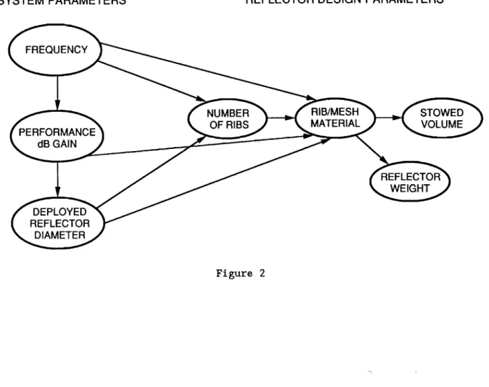
Figure 2 shows a system-level overview of the reflector design parameters. The number of ribs employed is determined by the antenna operating frequency and the reflector size. The hub diameter is also dependent on the number of ribs needed for proper rf operation. The reflector container height can be held to
approximately 3 percent of reflector diameter. The rib and mesh materials are selected to suit specific applications, e.g., at higher rf frequencies, ribs made of graphite/epoxy, and low CTE* mesh materials are needed to reduce the
deleterious effects of thermal distortion.
*Coefficient of thermal expansion (CTE).
SYSTEM PARAMETERS REFLECTOR DESIGN PARAMETERS
FREQUENCY
dB GAIN
DEPLOYED REFLECTOR
DIAMETER
NUMBER RIB/MESH STOWED
OF RIBS MATERIAL VOLUME
LMSC* REFLECTOR HISTORY
As shown in Fig. 3, LMSC Antenna Laboratory has been involved in the
development of the wrap-rib reflector technology for the past 20 years. To date, the designs of 3-, 6-, i0-, 20-, and 30-ft-diameter reflectors have been
manufactured and qualified for space application. The largest feasible diameter depends on the frequency of operation, but the designs for antennas as large as 150
ft in diameter have been studied. One of these studies led to a partial build of a 55-m-diameter antenna for a NASA contract during 1983-84.
*Lockheed Missiles and Space Company (LMSC).
LMSC DEPLOYABLE REFLECTORS 1963 1965 1970 1975 1980 1985 1
I
Figure 3 ORIGINAl: PAGEMOTOR-DRIVEN, FLEX-RIB ANTENNA UNFURLING
Over the past several years, Lockheed has studied several controlled deployment concepts. The controlled deployment concept will reduce the impact of a sudden release of stored strain energy in the ribs. This will also reduce the effect of sudden reaction force on the spacecraft.
Two main concepts are shown in Figs. 4 and 5. The first is based on a gear and motor system where the hub is turned by the motor, and the ribs are guided through a set of candles. The second deployment is based on power-driven tape. The tape
is attached to the central hub and wrapped circumferentially along every third rib. The tape travels over a set of idlers and then a slack take-up mechanics terminates at a spool that is part of the central hub.
The addition of these mechanism makes the design a lot more complicated alld adds substantially to the system weight. The controlled deployment system is not recommended until the ground test or other system constraints prove that it is
required.
Figure 4
WRAP-RIB TECHNOLOGY DEVELOPMENT
I
I I
Figure 5
ORIGINA£
PAGE
BLACK AND WHITE
PHOTOGRAPH
ORIGINAL PACE IS
OF POOR QUALITY
WRAP-RIB TECHNOLOGY STATUS
The ATS-6 spacecraft, shown in Fig. 6, carried a 30-ft-diameter wrap-rib
antenna made of aluminum ribs and Dacron mesh. It was designed to operate up to an 8 GHz frequency. The deleterious effect of thermal distortion in space limits the use of such a system to relatively low frequencies. To overcome this limitation, LMSC has worked extensively on the development of thermally stable materials for ribs and mesh. These advances have made it possible to design an antenna system operable at 25 GHz with only a very low-gain degradation of 0.75 dB.
_9
ATS-6 SPACECRAFT
Q GRAPHITE-EPOXY RIBS
I_ PROPRIETARY KEVLAR/BeCu MESH
I_ PASSIVE DEPLOYMENT
(_ deg 30-_ DIA
WORST CASE PERFORMANCE
MODERN WRAP RIB KEY FEATURES
O PROVEN TECHNOLOGIES
O VERIFIED ANALYSIS
D PASSIVE INTERMOD PRODUCTS < -150 dB
Figure 6
_RiGINAE PAGE IS OF POOR QUAL|TY'
WRAP-RIB TECHNOLOGY DEVELOPMENT
The wrap-rib technology development matrix, shown in Fig. 7, lists the various areas in which the technology development is taking place to meet the future
application needs for higher frequencies and larger diameters. Advances in materials and design methodology have resulted in thermally and visco-elastically
stable structure for the ribs. The same type of effort is focused in the area of developing thermally stable mesh designs. These activities in the rib and mesh materials are extensively supported by hardware tests. Some work has been done in
the controlled deployment concept development, but it has not attracted
concentrated attention. One of the major focuses has been to develop analytical methods to accurately predict the antenna far-field in an integrated way. The approach has been to integrate the various softwares in the rf and structural analysis areas.
I
I
I
RIB DESIGN MESH DESIGN
CONCEPT CONCEPT -- THERMALLY STABLE -- HIGHER STABILITY/WT MARGIN -- LIGHTWEIGHT -- LOW CTE -- BETTER MECHANICAL PROPERTIES - LOWER INTERMODE PRODUCT WRAP-RIB J TECHNOLOGY DEVELOPMENT
I
i
CONTROLLED DEPLOYMENT CONCEPT t MOTORIZED DEPLOYMENT TAPE DRIVENI
I ANALYTICAL r AND COMPUTER METHODS L INTEGRATED RF/MECH/THERMAL MODELING CODE Figure 7RISK REDUCTION STUDY -- RIBS
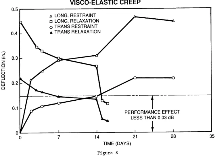
Figure 8 shows the tested visco-elastic behavior of the newly designed C-section rib made of graphite-expoxy. In this test the long-term, visco-elastic behavior was simulated by submerging the specimen in hot water for 28 days and then recording its recovery over the next 14 days. As shown in the figure, the visco-elastic creep recovered to well within the 0.03 dB performance loss target that was set as our design requirement. This result is of great significance due to the fact that when a rib gets wrapped around the hub, it is subjected to stress levels very close to its yield limit and this had a tendency to produce appreciable creep deformation in the rib.
05
VISCO-ELASTIC
CREEP
0.4 LONG. RESTRAINT n LONG. RELAXATION o TRANS RESTRAINT • TRANS RELAXATION t-_" 0.3 Z O I--O I..U -..I u. 0.2 I..U 0.1 0 I I 0 7 14 PERFORMANCE EFFECT LESS THAN 0.03 dB,
,
21 28 TIME (DAYS) Figure 8 35CTE STABILIZATION DATA
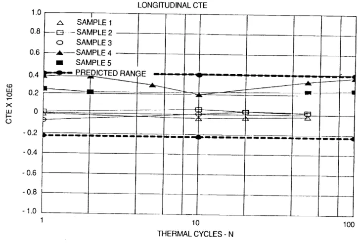
Figure 9 shows the results of CTE tests on the recently developed antenna
mesh. As mentioned earlier, wrap-rib antenna design is a mesh-dominated design and any distortion of the mesh directly translates into the antenna performance
degradation. Therefore, the goal was to design a zero CTE mesh, and from the test data one can determine that the new mesh CTE varies between -0.2 x 10 -6 to 0.4 x 15-6 in./in/°F. _o W O T--X W O 1.0 0.8 0.6 0.4 0.2 LONGITUDINAL CTE J -m I z I /x SAMPLE 1 --E_ -SAMPLE 2 --o SAMPLE 3 --,,6,-- SAMPLE 4 _ m SAMPLE 5 _--_--- PR_EDICTED__ RANGE"-_---_b,-_ ..._.__-- _____
og
....
_,-_ ... --ZX---0.2 I,---... _-... --_ -0.4 - 0.6 -0.8 - 1.0 10 THERMAL CYCLES - N Figure 9 100NEW MESH DATA
The material property table in Fig. i0 compares the data on the new mesh to other types of mesh. It is obvious that the new mesh outperforms the moly/gold Dacron in almost all the categories. For comparison, CTE improvement over the Dacron mesh which was used on the ATS-6 spacecraft is remarkable.
the and
BeCu - MoAu ATS
PROPERTY KEVLAR WEAVE 2310/1012 KNIT DACRON WEAVE
I[ m
0.289, 0.651 '1(-1(J) 0.480 0.167
ABSORPTIVITY/EMISSIVITY
CREEP RATE (_) (in./in./day)
WOOF_NALE WARP/COARSE
COEFFICIENT OF THERMAL
EXPANSION (10 "6/°F)
RF REFLECTIVITY (%)
SHEAR STIFFNESS (Ib/in.)
SHEAR OVERSTRAIN
TENSILE MODULUS (Ib/in.)
WOOF/WALE WARP/COARSE 0 0 -0.16 92.9 AT 25 GHz (SEE NOTE 4) PASS 45.9 19.3
9.1xlo_s
6.5 x 10"_ 2.8 99+ AT 25 GHz 1.9 FAIL 5.3 20.4o.s-_;2.o
®
99+ AT 8 GHz --+ PASS (SEE NOTE 5) (SEE NOTE 5) NOTES:1. HIGHER ode VALUE IS FOR BeCu-KEVLAR WEAVE WITH A FLAT BLACK SILICONE OVERCOAT.
2. DUE TO THE SCOPE OF THE TESTING PROGRAM, CREEP RATES LISTED ARE GENERAL TENDENCIES DERIVED FROM
THE DATA, NOT ABSOLUTE VALUES.
3. THE CTE FOR THE ATS DACRON MESH VARIES WITH TEMPERATURE FROM 12 x 10.6/°F AT -280°F TO 0.5 x 10 "6/°F AT
80°F, WITH A TRANSITION DROP OF 8 x 10⁶/°F OCCURRING AT -80°F.
4. SttEAR STIFFNESS TESTING SUSPENDED DUE TO BUDGETARY CONSTRAINTS.
5. FOR ATS DACRON MESH, ONLY MODULUS OF A SINGLE STRAND IS AVAILABLE. ESTRAND = 3.6 x 10⁵ PSI.
THERMAL EXPANSION OF KEVLAR-WRAPPED Cu, Be WIRE
Figure II shows the CTE stability of the new mesh over the temperature excursions to which antenna systems are subjected to while in an orbital
environment. Again, the average values of CTE printed on the charge proves the thermal stability the new mesh.
FIRST
THREE
RUNS ON SINGLE
SPECIMEN
2OO J o v--v 0 _J
<3 0 RUN NO. 1 CTE =-0.57 x 10⁻⁶/°C
o RUN NO. 2 CTE=-0.86x10⁻⁶/oc O RUN NO. 3 CTE =-0.40 x 10⁻⁶/°C
-200 -200 l -100 TEMPERATURE (°C) Figure ii I 0 100
INTEGRATION RF PERFORMANCE EVALUATION
The flow chart in Fig. 12 shows the schematic of the integrated software
analysis capability for antenna performance prediction. This spatial modeling of the antenna surface due to any perturbation mechanism includes the spacecraft dynamics and momentous transfer effect as a result of mechanical scanning. The analysis software can account for detailed thermal distortion as function of time and the orbital location. The rf prediction is based on physical optics
formulation which is being updated to include the edge diffraction time using GTD technique,
MESH _ _ SPIN
PRELOAD DYNAMICS
I OPTIMIZE OFFSET "I LFMR FIN,TE L ORB,TAL GXOPT REFLECTOR SURFACE ELEMENT MODEL I_TEMP GRAD
FEM ANALYTICAL DISTORTION MODEL DISTORTED SURFACE SPIN LOAD MESH PILLOWING WORST-CASE THERMAL I GXZPLT I FAR-FIELD PATTERN IN POLAR COORD GX MODEL
I I
I
FAR-FIELD CONTOUR PLOT THERM I i i I OUTPUTREFLECTOR
GEOMETRY
7
GXPOLY
I
I FORMULA I BODY DYNAMICSPACECRAFT FLEXIBLEEFFECTS
I GXHORN I CORRAND AMPLITUDEHORN PHASE
l_-s c
VECTORSi
,_
_I xo.,T
I
3D-PATTERNPLOT I MAIN BEAM,COPOLARCALCULATIONEFF FEED-PATTERN PLOT
RESULTS OF PERFORMANCE PREDICTION CODE
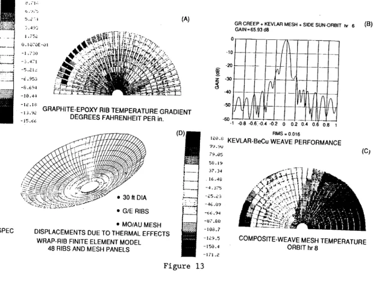
Figure 13 shows an example of the application of integrated software in solving the antenna far field. Segment (D) shows a finite-element model of 30-ft-diameter wrap-rlb antenna. Segments (A) and (C) show the spatial temperature distribution on a typical rib and mesh respectively. And finally, segment (B) gives the antenna far field for the side-sun case. The asymmetrical distortion of the reflector surface for this side-sun case is graphically evident by the shift of the peak of the main beam.
- _._ILA I) J:Ji FT:-,
(A)
-1_.16:
-t _.'_: GRAPHITE-EPOXY RIB TEMPERATURE GRADIENT
DEGREES FAHRENHEIT PER in.
-15.66
SPEC
GR CREEP + KEVLAR MESH + SIDE SUN-ORBIT hr 6 (B)
GAIN = 6593 d8 ' I I I i I -20 ... +-_-t ... •q qi |1 60 V I , -I -0,6-0.61-0.4-02 0 0,2 0,4 0.6 0.6 1 RMS = 0.016 RM
(D) _o._: KEVLAR-BeCu WEAVE PERFO ANCE
_._.os (C_
5_;. 19
-. ,)2...., _,_, 'i_ _
G/E RIBS i .1
•MO/AU MESH -_,'.E:o mm_ .......:_ .__
DISPLACEMENTS DUE TO THERMAL EFFECTS
WRAP-RIB FINITE ELEMENT MODEL
48 RIBS AND MESH PANELS
-108,7
-_,_'_,,s COMPOSITE-WEAVE MESH TEMPERATURE
-tso.4 ORBIT hr 8
-171 .c?.
Figure 13
TECHNOLOGY RESULTS
Figures 14, 15, and 16 compare the results of new technology over the old technology vis-a-vis a baseline performance of 30-ft-diameter wrap rib with 68 ribs for a 25 GHz application. Under the old technology, an aluminum rib and Dacron mesh are used for the two worst orbital thermal conditions. As can be easily seen,
the far-field pattern is badly degraded. There is approximately a 9 dB loss at 25 GHz. The same antenna made of composite mesh material and graphite-expoxy rib has only 0.3 dB loss for the worst thermal distortion case.
0 -10 2O z - 30 < _9 -40 50 6O SOLID 30 ft: 25 GHz: - 10 dB TAPER GAIN - 66.66 dB
68 RIBS: 25 GHz: UNDISTORTED FINITE
ELEMENT MODEL GAIN - 66.23 dB i ,ii
VV
!
- 0.8 - 0.6 - 0.4 - 0.2I
0 0 - deg-7_
I _ /_ 0.2 0.4 0.6 0.8 2z3
- 4t - 5( -6( A -0.8 -0.6 -0.4 -0.2 0 0.2 0.4 0.6 0.8 0 - degfi
llfL
'l( w
/kG = 0.43 dB (0.012 in. RMS) Figure 14OLD TECHNOLOGY
WILL NOT MEET REQUIREMENTS
0"
AL RIBS: DACRON MESH: ORBIT hr 12 GAIN - 57.07 dB -10 -- / _, - 20 -
30-<
//ijqr'
- 40. A - 60 -1 -0.8-0.6 -0.4 -0.2I
\
0 0.2 0.4 0.6 0.8 i 2 (,9 4 5 )(AL RIBS: DACRON MESH: ORBIT hr 6
GAIN - 58.28 dB
"_
-)
i
f
-0.8 -0.6 -0.4 -0.2 0 0.2 0.4 0.6 0.8 1 0- deg 0 - deg RMS = 0.056 RMS = 0.052 Figure 15(U) KEVLAR-BeCu
WEAVE PERFORMANCE
GR CREEP + KEVLAR MESH + ECLIPSE-ORBIT hr 12 GR CREEP + KEVLAR MESH + SIDE SUN- ORBIT hr 6
GAIN = 66.11 dB GAIN = 65.93 dB -10 ¸ 0 - deg RMS = 0.013 -10
l
-30-.0!
_/
°ot
-1.0 -0.8 -0.6 -0.4 -0.2 L/ 0 - deg RMS = 0,016LMSC 50-FT WRAP-RIB REFLECTOR
The LMSC Antenna Laboratory (Fig. 17) has been involved in the development of 50-ft-diameter wrap-rib antennas for some time. Some of the early work in this area could not design and build thermally and disco-elastically stable ribs using a C-section for the rib. Then the effort was directed toward a closed-section design called lenticular-section rib. This presented problems with the free deployment
characteristic of the wrap-rib antenna. The collapsed cross section of the lenticular rib could not recover fast enough to provide proper margin of stability. This meant that a controlled deployment device was needed.
Some of the most recent technology development effort has resulted in the design of a stable C-section rib which can be freely deployed.
GRAPHITE
EPOXY
RIB
KEY REFLECTOR REATURES
-- --1] tit rlh 'T i_l.1 -i <_'''"
MAX RMS ERROR__0.040
WEIGHT 280 Ib
STOWED DIAMETER__ 76 in.
4-RIB
- 3-GORE
REFLECTOR
SEGMENT
Figure 17
VIEW
OF REFLECTOR
HUB
ORIGfNAE PAGE
PROPOSED C-SECTION RIB
The proposed 50-ft-diameter reflector rib is shown in Fig. 18. The unique feature of this rib is the continuously staggered layers of center and edge lands as a function of rib length. Various other section properties are also listed.
wl(2 PL) RIB RADIUS = 5.15 in. ROOTHEIGHT = 7 in. LENGTH= 270 in. CENTERLANDWIDTH = 0.5 in, WEIGHT= 3.45Ib RIBTHICKNESS= 0.030in. -- W2 TI= n(_ PL) EDGE LANDS XN (in.) 0 7 23 4O 59 79 101 125 153 222 CENTER LANDS FN XN NO. OF (in.) LAYERS 10 0 9 15 2 32 7 5O 6 70 5 91 4 114 3 141 2 189 1 FN 10 9 8 7 6 5 4 2 1 ARC LENGTH(TIP)
L_k_l_
...
Figure 18 .... _= = * .... _ORIGINAL PAGE IS
SAFETY DESIGN FACTORS
Figures 19 through 22 show the design factors of safety for parameters such as torsional stability, bending stability, yeild stress, and charcteristic radius. As illustrated in the figures, these factors of safety have met or exceeded the design margins for l-g deployment and safe wrapping and unwrapping of the rib around the hub.
50
TRIAL
RIB FOR 50-ft ANTENNA
FACTOR OF SAFETY 4.0 3.0 2.0 m
/
0.0 0.0 25.0 50.0 L__l 1 L_L_I___ 75.0 100.0 125.0 150.0 175.0 200.0 225.0 250.0 275.0 AXIAL DISTANCE (in.)FACTOR OF SAFETY (TORSIONAL)
vs. AXIAL DISTANCE
5.0
TRIAL
RIB FOR 50-ftANTENNA
FACTOR OF SAFETY 4.0 3.0 2.0 1.0-0.0 25.0
/
L_I_I_L_I_I ! i 50.0 75.0 100.0 125.0 150.0 175.0 200.0 225.0 250.0 275.0 AXIAL DISTANCE (in.)FACTOR OF SAFETY (STRESS) vs. AXIAL DISTANCE
5.0
TRIAL
RIB FOR 50-ft ANTENNA
FACTOR OF SAFETY 4.0 3.0 2.0 1.0 0.0' 0.0 I I I I I I I I 25.0 50.0 75.0 100.0 125.0 150.0 175.0 200.0 AXIAL DISTANCE (in.)
]_Ll
225.0 250.0 275.0
CHARACTERISTIC
RADIUS
vs. AXIAL
DISTANCE
100.0
TRIAL
RIB FOR 50-ft ANTENNA
RADIUS (in.) 80.0 60.0 40.0 20.0 -0.0 0.0
L
\--I I I I I I I I I I _ 25.0 50.0 75.0 100.0 125.0 150.0 175.0 200.0 225.0 250.0 275.0 AXIAL DISTANCE (in.)STRUCTURAL CHARACTERISTICS
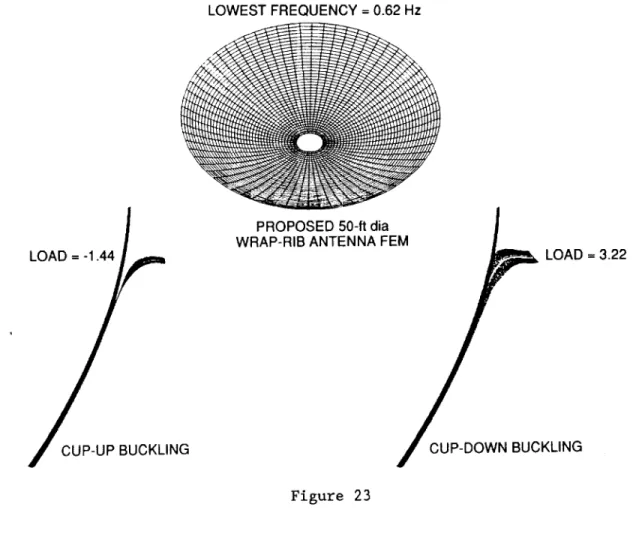
Figure 23 shows the structural characteristics of the 50-ft-diameter rib. Its lowest structural frequency is 0.62 Hz, which is the pin-wheel mode. Cup-up and cup-down stability numbers give the margins of the reflector's stability in a I-G loading environment.
CUP-UP BUCKLING
LOWEST FREQUENCY = 0.62 Hz
PROPOSED 50-ft dia
WRAP-RIB ANTENNA FE LOAD -- 3.22
CUP-DOWN BUCKLING Figure 23
FAR-FIELD PERFORMANCE
Figure 24 showns the far-field performance of the 50-ft-diameter antenna for theworst distortion case. This was generated using the integrated rf/mechanical analysis code. This shows that far-field gain is quite respectable even for the worst case.
50ft.DISH DISTORTED FOR SIDESUN
0 -1D--20 -30 (.9 -40 • -S0" -60 -70 -I
GR/E RIBS: COMPOSITE MESH: UNDISTORTED WRAP-RIB GAIN = 68.30 DB 1800 DEG I 1 I __+ .__ i
_i
-0.8 -0.6 -0.4 -0.2l
0 B-DEG ¢ =o.oDEGt
1
i • ! 0.2 04 06 0.8 __,.,p.__ 1 -10 -20 o30 (D -40GR/E RIBS: COMPOSITE MESH: SIDE SUN GAIN = 66.63 DB = 180.0 DEG ¢ = 0.0 DEG -50 -60 -70 -1 -0.8 -0.6 -0.4 -02 !
J/A
',.J3 0 0.2 0.4 0.6 0.8 6 -DEG Figure 24BASELINE 50-FT-DIAMETER WRAP-RIB DESIGN DATA
Figure 25 list an approximate system weight of a typical 50-ft-diameter
wrap-rib antenna to be operable up to 20 GHz. The total weight of 522 ib assumes the hub structure is made of aluminum. This can be easily replaced by a graphite-epoxy material which will result in substantial weight saving.
HUB OUTER DIA
97 in.
HUB INNER DIA
72 in.
HUB WEIGHT
124 Ib (ALUMINUM)
HUB HEIGHT
12 in.
TOTAL RIB WEIGHT
238 Ib (FOR 68 RIBS)
TOTAL MESH WEIGHT
10 Ib
APPROXIMATE
FEED SUPPORT
150 Ib
STRUCTURE
WEIGHT
TOTAL APPROXIMATE
WEIGHT
522 Ib
CONCLUSIONS
The technology for a 50-ft-diameter wrap-rib reflector for radiometric
application for frequencies up to 20 GHz is near term. The elements of the total system can be designed to meet the specification. A full-up system build and contour verification must be accomplished before this size reflector can be declared space qualified.