Downloadable Sounds Level 1
Version 1.1b
September 2004Published By: The MIDI Manufacturers Association Los Angeles, CA
PREFACE
This document and the underlying specification is the result of extensive research and discussion by a group of hardware and software manufacturers to determine a base-line architecture which will support playback of "downloadable" sounds. It was the goal of this group to determine an architecture that would be similar enough to the majority of existing products to allow fast time to market, without sacrificing performance. The specification is particularly aimed at multimedia computing applications and platforms.
The discussion and drafting of this specification occurred in meetings and via email over a one year period under the auspices of the Interactive Audio Special Interest Group’s Downloadable Sounds Working Group (IASIG DSWG). Members of this group also met at various times as the Downloadable Sounds Device Architecture Working Group (DSDAWG) and the Downloadable Sounds API and File Format Working Group (DSAFFWG). A complete list of DSWG members is on record with the IASIG.
In order to improve audio performance on multimedia platforms beyond today's capabilities, the specification includes guidelines for a Level 2 feature set, which can not be supported on much of the current installed base but is more in-line with what is commonly considered state of the art today. Development of the Level 2 specification will be an on-going process.
This document is in two parts. The first part describes the playback device architecture, and how device parameters will be defined. The second part describes a standard file format for distributing these samples. Recommendations are also planned for the protocol and messages to be used in creating standardized processes for initiating and managing downloading, so that applications, devices, and platforms can all be compatible.
DLS playback device must be able to accurately, within specific guidelines, play back files properly authored to this specification. Certification of DLS compatibility is therefore required of all Manufacturers of DLS compatible devices and related products. Companies should contact the MMA to receive information about testing procedures, and obtain test materials and certification.
The MMA, IASIG, and all members shall not be held liable to any person or entity for any reason related to the adoption, implementation or other use of this document or the specification herein. Note: Version 1.1b contains only one change from 1.1.a, which is the removal of
“Expression” from the list of controllers that are not reset when RAC = “0”. This is an editorial correction, since all known implementations already worked this way.
Copyright 1995-1998 MIDI Manufacturers Association Incorporated
ALL RIGHTS RESERVED. NO PART OF THIS DOCUMENT MAY BE REPRODUCED OR TRANSMITTED IN ANY FORM OR BY ANY MEANS, ELECTRONIC OR MECHANICAL, INCLUDING INFORMATION STORAGE AND RETRIEVAL SYSTEMS, WITHOUT PERMISSION IN WRITING FROM THE MIDI MANUFACTURERS ASSOCIATION. Printed 2004
MMA PO Box 3173
Contents
CHAPTER 1: DEVICE ARCHITECTURE...1
INTRODUCTION...1 THE PROBLEM...1 THE SOLUTION...1 OBJECTIVES...2 DESIGN OVERVIEW...3 CONTROL LOGIC...3
DIGITAL AUDIO ENGINE...3
ARTICULATION MODULES AND CONNECTIONS...4
CONTROL LOGIC...4
MELODIC INSTRUMENT...6
DRUM KIT...6
NOTE EXCLUSIVITY...7
VOICE ALLOCATION...7
BANK SELECT AND PROGRAM CHANGE...8
DIGITAL AUDIO ENGINE ...9
DIGITAL OSCILLATOR...9
DIGITALLY CONTROLLED AMPLIFIER...10
ARTICULATION MODULES AND CONNECTIONS ...10
LOW FREQUENCY OSCILLATOR...10 ENVELOPE GENERATOR...11 PERFORMANCE CONTROLLERS...14 ARTICULATION ARCHITECTURE...16 DATA OBJECTS ...24 OBJECT HIERARCHY...24 DATA FORMATS...25 INSTRUMENT...26 REGION...26 WAVE LINK...26 ARTICULATION...27 WAVE SAMPLE...27 MINIMUM REQUIREMENTS ...28 IMPLEMENTATION NOTES...28
DEVICE DRIVER DESIGN NOTES...28
APPLICATION DESIGN NOTES...29
INSTRUMENT DESIGN NOTES...29
EXAMPLES...30
CHAPTER 2: FILE FORMAT...35
PURPOSE... 35
ADVANTAGES OF THE DLS FORMAT ... 36
ADHERES TO STANDARD RIFF LAYOUT... 36
SIMPLE STRUCTURE... 36
USES STANDARD WAVE FILES... 36
EASY AND UNLIMITED EXPANSION... 36
DOWNLOADABLE SOUND COLLECTION RIFF FILES ... 36
LIST CHUNK... 38
<COLH-CK>, COLLECTION HEADER CHUNK... 38
<DLID-CK>, DLSID CHUNK... 38
<INSH-CK>, INSTRUMENT HEADER CHUNK... 40
<RGNH-CK>, REGION HEADER CHUNK... 41
<ART1-CK>, LEVEL 1 ARTICULATOR CHUNK... 42
<WLNK-CK>, WAVE LINK CHUNK... 44
<WSMP-CK>, WAVE SAMPLE CHUNK... 45
<PTBL-CK>, POOL TABLE CHUNK... 46
<VERS-CK>, VERSION CHUNK... 47
<INFO-LIST>, INFO LIST CHUNK... 48
CODING REQUIREMENTS AND RECOMMENDATIONS... 50
FILE EXAMPLES... 52
GENERIC DLS LEVEL 1 FILE... 52
DLS LEVEL 1 FILE WITH 3RD PARTY EXTENSIONS... 53
PROPRIETARY CHUNK IDS ... 55
APPENDIX A PARAMETER UNITS... 56
APPENDIX B TRANSFORM AND PAN FUNCTIONS ... 57
APPENDIX C DLS HEADER FILE ... 59
APPENDIX D DLS LEVEL 1 WAVE FILE FORMAT ... 63
DATA PACKING FOR WAVE_FORMAT_PCM FILES... 64
DATA FORMAT OF THE WAVE_FORMAT_PCM SAMPLES... 65
APPENDIX E INSTRUMENT OBJECT HIERARCHY AND <DLS-FORM> ... 66
REFERENCES... 67
ERRATA FOR VERSION 1.1... 68
“ATTENUATION” VS. “GAIN” (ENTIRE DOCUMENT)... 68
NOTE EXCLUSIVITY (PAGE 7)... 68
ENVELOPE DIAGRAM (PAGE 12) AND SEGMENT DESCRIPTIONS (PAGE 13-14)... 68
Figures
FIGURE 1. LEVEL 1 DEVICE—BLOCK DIAGRAM...5
FIGURE 2. REGION...5
FIGURE 3. MELODIC INSTRUMENT HIERARCHY...6
FIGURE 4. DRUM KIT HIERARCHY...6
FIGURE 5. DIGITAL AUDIO ENGINE—BLOCK DIAGRAM...9
FIGURE 6. SAMPLE...10
FIGURE 7. AMPLITUDE ENVELOPE OVERVIEW...12
FIGURE 8. ATTACK TIME...12
FIGURE 9. DECAY TIME...13
FIGURE 10. SUSTAIN LEVEL...13
FIGURE 11. RELEASE TIME...13
FIGURE 12. CONNECTION BLOCK...17
FIGURE 13. SCALED CONNECTION BLOCK...17
FIGURE 14. SCALED SOURCE CONNECTION BLOCK...18
FIGURE 15. CONTROLLED SCALED SOURCE CONNECTION BLOCK...18
FIGURE 16. CONNECTION GRAPH...21
FIGURE 17. DLS FILE STRUCTURE...35
FIGURE 18. CONCAVE TRANSFORM...57
FIGURE 19. PAN CONTROL VERSUS STEREO OUTPUTS...58
FIGURE 20. DLS LEVEL 1 ENVELOPE DIAGRAM (CORRECTED) ...70
Tables
TABLE 1. CONNECTION BLOCK...23TABLE 2. DLS LEVEL 1 DEFAULT, MINIMUM, MAXIMUM AND UNIT VALUES FOR CONNECTION BLOCKS...24
TABLE 3. EXAMPLE DLS PARAMETERS...31
Chapter 1: Device Architecture
Introduction
As wavetable (WT) synthesis architectures have become increasingly prevalent, the need for a standard format for defining musical instruments has grown in proportion.
Although the General MIDI (GM) specification for 128 instrument presets helps to a small degree, it lacks both the depth and breadth to deliver a truly consistent playback experience across a wide range of platforms.
There is a need for a musical instrument standard that allows composers to define exactly how each musical instrument sounds on a wide variety of playback devices.
The Problem
When authoring for MIDI, a composer faces two limitations: 1. General MIDI provides a very limited set of 128 instruments.
2. Even within the predefined GM set, there isn’t enough consistency. This inconsistency ranges from subtle to outright ridiculous. A piano on one card may sound like an organ on another. Other media do not suffer from these problems. An author of graphics or wave audio can rely on consistent results on multiple hardware solutions. Yet there is no such standard for MIDI. Because of this, many content providers have opted for digital audio (which delivers an exact digital recording of a performance) in order to resolve the common playback experience problem. Unfortunately, digital audio is a very inflexible medium. It is poor at delivering interactive music solutions. Additionally, its storage requirements are orders of magnitude greater than that of MIDI. This latter point is of particular significance in places where data bandwidth is at a premium, for example on the Internet.
The Solution
The Downloadable Sounds Level 1 Architecture enables the author to completely define an instrument by combining a recorded waveform with articulation information. An instrument designed this way can be downloaded onto any hardware device that supports the standard and then played like any standard MIDI synthesizer.
Together with MIDI, it delivers the following benefits:
! A common playback experience, unlike GM.
! An unlimited sound palette for both instruments and sound effects, unlike GM.
! True audio interactivity, unlike digital audio.
With the industry-wide adoption of this standard for downloadable sounds, MIDI will blossom as a superior solution for quality interactive music on the personal computer.
To achieve this end, a consortium of wavetable solution vendors has hammered out a
recommendation for an industry standard for downloadable instruments. This specification is the end result of that effort.
This specification is intended to be a base level specification. It defines synthesis attributes that can be implemented today with the majority of off-the-shelf sound cards and chip sets. As such, we refer to this as the Level 1 specification, with the intention that a Level 2 specification will follow in the future. Level 2 will represent a richer set of capabilities that may not be attainable with many of today’s products.
Objectives
The Level 1 Downloadable Sounds specification is designed to meet several objectives:
1. The specification must work for all or most current hardware solutions and computer platforms that support downloadable instruments.
2. The specification must be precise enough that it can guarantee a common playback
experience. A specific combination of a MIDI sequence and downloadable instruments should sound extremely consistent from platform to platform.
3. The specification must be extensible so it can grow with time. Although the Level 1
specification must work with existing hardware, the Level 2 specification should anticipate and even help define silicon solutions currently in the design stage that represent the next
generation of wavetable hardware.
4. The specification must be extensible to naturally support streaming of digital audio and real-time sound downloads. Even if these features can not be supported now, the design must not preclude their support in the future.
5. The specification must be open and non-proprietary.
The first objective is the most important. A standard that cannot be implemented immediately across the board is destined for failure. Amazingly, achieving this consensus has been surprisingly painless. Years of industry experience and legacy have already defined a base level synthesis architecture consisting of several key components:
! A sampled sound source with loop points.
! A low-frequency oscillator to control vibrato and tremolo.
! Two simple envelope generators to define volume and pitch envelopes.
! Standard behavior in response to MIDI events such as Pitch Bend and Mod Wheel. The Downloadable Sounds specification starts with this bare bones functionality and delivers an implementation that works well on any synthesis hardware that supports these components. The specification also looks to the future and takes an extensible approach that allows the
Design Overview
A musical instrument defined by a sound sample is much more than a simple wave file. In addition to the actual sample data and associated loop information, the instrument must indicate under what circumstances each sample should be used, and how to modulate, or articulate, the sample as it plays.
A generic sample-playback synthesis architecture can be broken down into three distinct subsystems:
1. Control logic 2. Digital audio engine
3. Articulation modules and connections
Control Logic
The control logic receives a MIDI note event and determines which instrument should play the note, and, within that instrument, which sample and articulation combination to use.
Choosing the instrument requires little more than observing the MIDI channel number in the event and selecting the proper instrument accordingly.
Choosing the sample and articulation to use is not as simple. Almost all sampled synthesis architectures employ some method of organizing samples by note range across the keyboard. In addition, multiple samples can be used to represent different velocity ranges and multiple samples can be played at once to create a layered, richer sound.
Terms such as layers, splits, blocks, and regions are commonly used in synthesizer jargon to refer to the management of multiple samples. For the purposes of this specification, we refer to them as regions.
The Level 1 specification implements a bare bones approach with no velocity cross-switching and no layering.
Digital Audio Engine
The digital audio engine is certainly the most obvious part of the synthesizer. It is composed of a playback engine, or digital oscillator, and a digitally controlled amplifier.
The digital oscillator plays a sampled sound waveform, managing loop points within the waveform so the sound can play continuously if needed. And, as the note plays, it responds to changes in pitch, allowing for real time expression such as vibrato and pitch bend.
The digitally controlled amplifier modulates the loudness of the instrument. Importantly, this is used to control the amplitude shape, or envelope, of the note. However, it is also used for other types of real-time expression, such as tremolo.
Pitch and volume control of the oscillator and amplifier are critical because they define the shape of the sound as it plays, and allow it to be dynamically responsive in real time, giving the sampled instrument much more expression than the simple digital audio playback could ever provide. Real-time control of these parameters comes from modules in the Articulation section which generate a constant stream of changing pitch and volume to which the digital audio engine responds.
The digital audio path represents the journey the sound takes from the oscillator to the amplifier to the digital-to-analog converter (DAC). This path can optionally include additional modules, such as filters and effects devices, that process the sound as it flows from oscillator to DAC.
The Level 1 specification implements a simple digital audio engine composed of an oscillator, amplifier, and DAC. The oscillator supports looped as well as one-shot samples.
Articulation Modules and Connections
The articulation modules are a set of devices that provide additional control over the pitch and volume of the sample as it plays.
The articulation modules include low frequency oscillators (LFOs) to contribute vibrato and tremolo, envelope generators to define an overall volume and pitch shape to the sample, and MIDI real-time controllers, such as Pitch Bend and Mod Wheel, to give the music real-time expression.
Generally, these modules can be linked in different ways to provide different results. For example, an LFO might generate a sine wave which modulates the pitch of the sample for vibrato or the volume of the sample for tremolo. Modules can also receive as well as send control signals. An envelope generator might use key velocity to influence the attack time of the envelope.
Articulation modules can be configured in different ways, and this configuration is an important part of the instrument definition. In fact, the term patch as used for an instrument preset refers to the early days when the hardware modules in an analog synthesizer were “patched” together with cables, which routed signals from module to module.
The ability to configure the modules is important because it yields a flexible approach to
synthesizer design. At the same time, it is important to define a base level configuration that can be supported by all hardware.
For these reasons, the Level 1 specification is relatively rigid. It defines a preset routing
arrangement that is simple enough to be supportable by existing hardware. Fortunately, it is also a musically logical and useful configuration.
Significantly, the specification maps the routing onto a flexible system, so it can grow into Level 2 and beyond.
It is important to understand that this is purely a symbolic system that can be mapped on many different hardware designs. Do not think of it as the recipe for a specific method for building synthesis architectures. It should be flexible enough to provide a common language between different hardware implementations.
Now that we have a reasonable overview of the three primary components of the synthesis architecture, we can investigate each in much greater detail, with attention to the Level 1 specifications.
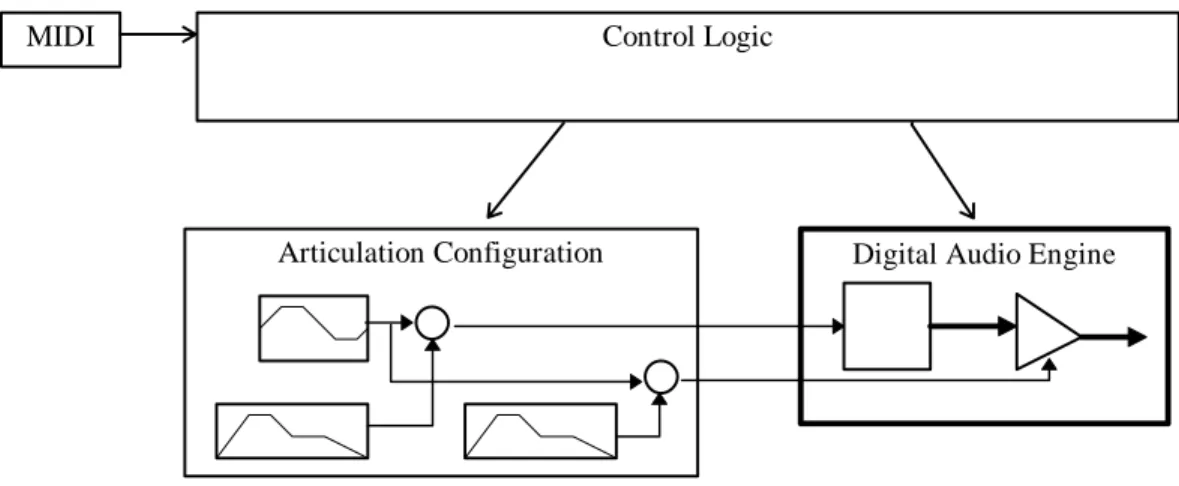
Control Logic
The control logic implementation in the Level 1 specification is relatively simple. The control logic receives bank select and program change commands to select the instrument on a particular channel, and MIDI note on and off events to play notes on the same channel.
The control logic uses the combination of instrument choice (bank select and program change) and note to select a specific configuration of the articulation modules and digital audio engine to perform the note.
MIDI Control Logic
Articulation Configuration Digital Audio Engine
Figure 1. Level 1 Device—Block Diagram
For the digital audio engine, the control logic must select a specific sample to play. The sample is indirectly accessed through a region. The region defines the key range and velocity range used by the control logic to select the sample. It also determines a preset value for the overall amplitude of the sample and a preset tuning. The sample, in turn, defines the actual chunk of digitized sound along with control parameters such as loop points, sample rate, and so on.
Region Sample
Figure 2. Region
The articulation is a complete configuration of articulation modules and their connections,
including the envelope generators and LFO. These define how the note should be articulated as it plays.
To facilitate compatibility with existing synthesizers, Level 1 imposes the following limitations:
! There are two distinct instrument types: Melodic and Drum Kit.
! There can be only one Drum Kit and its use is restricted to MIDI channel 10.
! The Level 1 synthesizer is not required to support the MIDI Bank Select messages CC0 and CC32. Therefore, on some synthesizers, the minimum number of instruments could be restricted to 128 melodic instruments (including GM instruments for those devices that also support GM). If the Level 1 synthesizer does not support Bank Select, the Level 1 Device Driver must virtualize the Bank Select messages by mapping Bank Select messages sent by the application to the device’s address space.
The primary difference between Melodic and Drum instruments is how they pair up articulations and regions. Melodic instruments usually require anywhere from one to a dozen or more samples to define the same sound over the range of the keyboard. Since it is all one instrument, only one
articulation configuration is required. On the other hand, a drum kit by nature defines a complete cast of different instruments, so each drum must be treated individually.
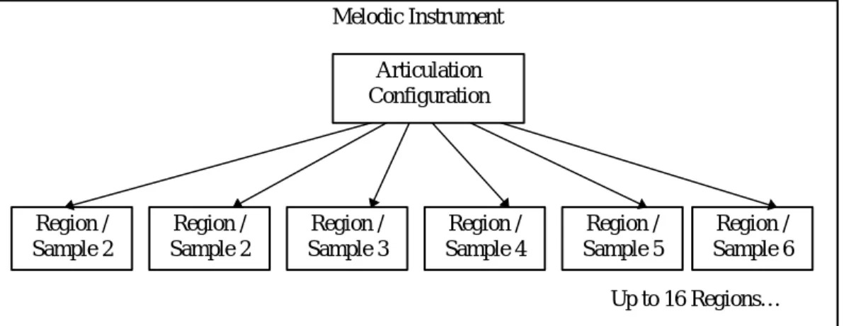
Melodic Instrument
A Level 1 melodic instrument is composed of one global set of articulation parameters and up to 16 regions.
Each region defines a specific range of keyboard notes that it can play. Therefore, a melodic instrument uses up to sixteen keyboard splits to cover the pitch range of the sound.
Articulation Configuration Region / Sample 2 Melodic Instrument Region / Sample 3 Region / Sample 5 Region / Sample 4 Region / Sample 6 Up to 16 Regions… Region / Sample 2
Figure 3. Melodic Instrument Hierarchy
Although the region structure can also define a velocity range, the Level 1 specification does not support velocity cross-switching.
Because there is only one articulation configuration per instrument, all of the samples (up to 16) are played against one global set of articulation data (envelopes, LFOs, etc.).
Drum Kit
Drum kits comprise a complete set of different sounds. Each drum requires a unique sample and requires its own articulation configuration.
A Level 1 drum kit contains up to 128 regions, one for each drum note. It also includes up to 128 articulation configurations, also one for each drum note.
Articulation Configuration 1 Articulation Configuration 2 Region / Sample 2 Articulation Configuration 3 Region / Sample 3 Articulation Configuration 4 Region / Sample 4 Articulation Configuration 5 Region / Sample 5 Region / Sample 1 Drum Kit
Up to 128 Articulations and Regions…
Each articulation configuration maps to a unique region, which in turn points to a specific sample. The region can define a single key or a contiguous range of keys. The sample does not
necessarily have to be unique—several regions can point to the same sample.
Only one drum kit is allowed at a time. When a device supports both Level 1 and General MIDI, the device may share MIDI channels between Level 1 and General MIDI. In such a device, it will not be possible to use the General MIDI drum kit and the Level 1 drum kit simultaneously. Level 2 should remove the distinction between drum kits and melodic instruments. All instruments should support 128 regions, etc. However, the wide range of existing hardware implementations cannot support such a generalized requirement.
Note Exclusivity
The Level 1 Device has provisions for two forms of note exclusivity on a MIDI channel basis. The first form of exclusivity involves notes on a MIDI channel with the same MIDI note number. By default, if a MIDI Note-On event is received and there are oscillators previously assigned to the same MIDI note and MIDI channel which have not received a Note-Off event, the control logic will issue a Note-Off to those oscillators. However, there is a flag in the usKeyGroup field in the region header chunk that, when set, will defeat this logic. When the Non-Self-Exclusive flag is set, Note-On events for a particular MIDI note number on a MIDI channel do not trigger Note-Off events for oscillators assigned to the same MIDI note and MIDI channel. When the Non-Self-Exclusive flag is not set and a second Note-On event of the same MIDI note number on the same MIDI channel is received by the synthesis engine, the second Note-On will be played as well as the first. The Non-Self-Exclusive flag is off by default..
The second form of note exclusivity is useful for drums and sound effects. Each region can be assigned a key group. If a Note-On event is received and there are oscillators that have been assigned to play a region that has the same Key Group number as the region for the new Note-On, a Note-Off event is issued to the other oscillators. As an example, this can be used to create mutually exclusive Open, Closed and Pedal High Hat sounds for a drum group. A second example might be in a sound effects bank to stop a squeaking door sound when the door finally closes.
For Level 1, this is implemented as a usKeyGroup with a range of 0 to 15. usKeyGroup equal to 0 indicates a non exclusive key group. For Level 1, this mutually exclusive mode is limited to Channel 10.
Voice Allocation
Voice Allocation is the means by which digitally controlled oscillators are allocated to play samples as dictated by the instrument parameters and the MIDI data stream. Ideally, there should be enough to play every note and sound effect in the score. However, this may not always be the case. Some Level 1 devices may have more oscillators than others, and the developer may choose to develop a score that uses more than the minimum amount of polyphony to take advantage of this. This leads to the case of what to do when the score calls for more oscillators than the device is capable of producing. We would prefer to see a graceful degradation where the developer can accurately predict the end result.
To satisfy this need, the Level 1 device defaults to static MIDI channel priority. In this scheme, each MIDI channel is assigned a priority, with the drum channel (MIDI channel 10) given the highest priority, followed by the remaining channels in ascending numeric order (10,1-9,11-16). When a Note-On event is received, the Control Logic must first attempt to satisfy the request using a free oscillator. If all oscillators have been previously allocated, then an oscillator must be “stolen”; that is to say, the previous note is silenced, and a new note is begun. Using static MIDI
channel priority, an oscillator assigned to a note on channel 16 would be stolen before one on channel 15, and so on. Notes on lower priority channels cannot steal oscillators assigned to notes on higher priority channels under any circumstances. For example, if a Note-On is received on channel 11, and all oscillators are currently assigned to notes on channels 10 and above, then the new note is not played. This logic applies even to notes in the Release phase, i.e. after a Note-Off has been received.
The designer of a Level 1 device is free to use any other voice allocation heuristic, provided that the channel priority heuristic is satisfied first. This flexibility allows for further prioritization within the channel, such as released notes vs. unreleased notes, “inside” versus “outside” voices, or any other scheme that the developer cares to implement.
The DLS device will be in static MIDI channel priority by default (or upon entering DLS mode if equipped for multiple modes of operation), and when it receives the DLS System On message. This static MIDI channel priority mode can also be enabled or disabled through a DLS System Exclusive message. To turn off static MIDI channel priority, a programmer would send the DLS Voice Allocation Off System Exclusive message (F0h 7Eh <device ID> 0Ah 03h F7h). As is common for this type of MIDI Message, <device ID> = 7Fh means the message is intended for all DLS devices in the system. To restore static MIDI channel priority, a programmer can send the DLS Level 1 Voice Allocation On System Exclusive message (F0h 7Eh <device ID> 0Ah 04h F7h), or reset the device with the DLS System On message. DLS Voice Allocation System Exclusive messages have no effect on a DLS device which is not currently in DLS mode. Please see the MIDI Specification for more details on System Exclusive Messages.
When static MIDI channel priority is turned off, device manufacturers may use any voice allocation heuristic, but consistent playback on any DLS Level 1 device can not be guaranteed except in static MIDI channel priority mode. Applications which modify the voice allocation mode should always return it to the default state upon exiting.
While Level 1 does not allow for layering of oscillators for instruments, a Level 1 device that also supports General MIDI may use layering to implement its GM instruments. The GM instruments should use the voice allocation heuristics described here when the device is operating in Level 1 mode. However, it is left to the discretion of the device designer to determine the heuristic for the second layer of a General MIDI instrument. For example, the device designer may elect to steal the second layer of a GM instrument to satisfy a Note-On event, regardless of the priority of the channels.
Level 2 should add a dynamic prioritization scheme that allows the developer to assign priority to individual notes as they are played.
Bank Select and Program Change
The Level 1 device will support Bank Select and Program Change MIDI messages as the method of selecting the instrument to be played on a MIDI channel. Because some Level 1 devices may not support Bank Select internally, the designer has the option of providing this support in the device driver by virtualizing the Bank Select messages. In this case, a DLS Level 1 is required to support only a single melodic instrument bank, and each downloaded instrument may go into this single bank. This mechanism is defined in the DLS Level 1 Protocol and Messaging Guidelines using the Download with Lock command (see Reference).
The Bank Select address space consists of 16,384 banks, represented by the MIDI Controller Change MSB and LSB Messages (controllers 0 and 32, respectively), with each bank supporting up to 128 instruments for a total address space of over 2 million instruments.
DLS Level 1 specifies that a downloadable sound can be placed in any bank/instrument location in MIDI space. To avoid conflicts with Roland's GS, Yamaha's XG and any other manufacturer's MIDI bank mapping scheme, programmers are required to send the DLS System On (F0h 7Eh
<device ID> 0Ah 01h F7h) message prior to using the DLS device. This message will enable a downloaded instrument to be loaded into any bank/instrument location in MIDI space and enable the device to operate as a DLS device. If a download is to a manufacturer's proprietary MIDI bank/instrument location, the device is required to play back the downloaded sound and not the manufacturer's proprietary sound. When the downloaded sound is removed from the MIDI bank/instrument location, the device should again play back the manufacturer's proprietary sound. All manufacturers of DLS Level 1 devices are required to support this message. To turn DLS functionality off, send the DLS System Off message (F0h 7Eh <device ID> 0Ah 02h F7h). Sending a <device ID> = 7Fh will be a broadcast message to all DLS devices.
To detect whether a given instrument is a drum or melodic instrument, a program should check the instrument header's ulBank field bit 31 in the DLS Level 1 file format. If ulBank bit 31 is equal to 1, the instrument is a drum instrument. If ulBank bit 31 is equal to 0, the instrument is a melodic instrument. The distinction between drum and melodic instruments will cease to exist in a future revision of the DLS specification.
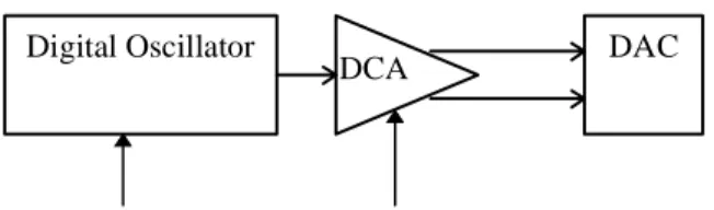
Digital Audio Engine
The Level 1 digital audio engine is relatively simple. Other than the digital oscillator and digitally controlled amplifier, there are no other modules on the digital signal path.
Digital Oscillator
DCA DAC
Pitch Control Volume Control
Figure 5. Digital Audio Engine—Block Diagram
Digital Oscillator
The digital oscillator is handed a sample to play by the control logic. It performs the sample, all the while modulating the pitch of the sound with the control stream from the articulation set.
The sample data can be 16-bit two's complement or 8-bit offset two's complement (often referred to as 8-bit unsigned data, with zero represented as 0x80). This complies with the both the RIFF WAVE PCM format and common practice on the Macintosh. To convert between offset two's and standard two's complement (signed 8 bit, -128 to +127), XOR each byte of the source sample value with 0x80.
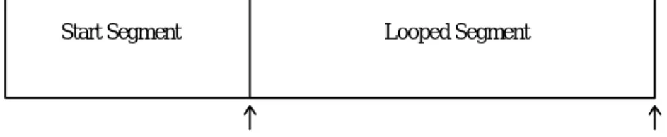
The sample defines whether it is to be played once through or looped. If looped, the sample supports one looped region, as defined by a pair of fixed sample data point indices. The loop start specifies the first sample data point in the loop, while the loop end specifies the first sample data point beyond the end of the loop. There is no fractional component to the loop points.
Start Segment Looped Segment
Start Point End Point
Sample Buffer
Figure 6. Sample
The sample structure also defines the MIDI note number and fine tune for the recorded
instrument. For example, the sample might be a recording of a C# octave 4 piano key that’s just a little flat.
It also defines the sample rate of the recording. Between this and the tuning information, the digital oscillator has everything it needs to pitch shift the sample appropriately for the intended pitch.
The Level 1 digital oscillator must be capable of pitch shifting the sample with a range of up two octaves and down four octaves. This pitch shift is the sum total of all tuning parameters, including sample fine tune and MIDI pitch bend. And the Level 1 digital oscillator is required to operate at a minimum playback rate of 22.05 kHz and is required to support a minimum of 24 simultaneous voices.
Level 2 should address issues such as extensions for additional loop types, fractional loop indices, data compression, higher maximum output sampling rate, and polyphony greater than 24 voices.
Digitally Controlled Amplifier
The second module in the signal path is the digitally controlled amplifier (DCA). It takes the output of the oscillator and modulates the volume, responding to controls from the articulation section, of which the amplitude envelope is probably the most important.
The MIDI pan signal is fed through a transform that converts to left and right amplitude signals. These signals are fed separately into the DCA to generate stereo output from the monophonic signal entering the DCA.
Level 2 should address additional capabilities such as low-pass filtering and digital effects (reverb, chorus, etc.) which can be represented by modules in the digital signal path.
Articulation Modules and Connections
The Level 1 set of Articulation modules include an LFO, two envelope generators, and several MIDI controller inputs. A configuration is defined by connecting this base set of modules and setting the controls for each one. The Level 1 set specifies the controls available on each module and a required set of connections to link the modules together.
Low Frequency Oscillator
The LFO generates a periodic waveform that is used to modulate the pitch or volume of the instrument. Level 1 requires just one shape —a sine wave—although a triangle wave may be substituted.
NOTE: When applied to pitch, the LFO will vary the pitch of the oscillator in a bipolar fashion. For example, if the lScale value for the LFO to Pitch connection is set to 50 cents, then the oscillator pitch will vary from +50 cents to –50 cents.
When applied to attenuation, the LFO will vary the attenuation of the DCA in a unipolar fashion. For example, if the lScale value for the LFO to Attenuation connection is set to 3dB, then the DCA output will vary from 0dB to –3dB.
Frequency
The frequency control sets the wave frequency between 0.1 Hz and 10 Hz.
Start Delay Time
The LFO starts after a preset delay time. If it cannot synchronize the wave cycle to start with a 0 bias, it should ramp up to full volume over a one cycle period.
The delay time control sets the initial delay within the 10 ms to 10 second range.
Level 2 should consider multiple wave shapes, greater frequency ranges, and definable ramps.
Envelope Generator
The envelope generator creates a four-section segmented envelope. The segments correspond to the attack, decay, sustain, and release sections of the traditional analog ADSR (Attack, Decay, Sustain, Release) design.
When the note starts, the envelope enters the attack segment, increasing until it reaches the peak level. It then enters the decay segment and decreases to a steady level—the sustain level—which holds until a MIDI note off is received. When the note ends, the envelope enters the fourth segment, the release section, and decays out.
The Level 1 scenario accommodates one-shot sample files that require no envelope. This is accomplished by setting the attack duration to 0 and sustain and release values to maximum. For design consistency, the signal levels from the envelope generator are represented in an exponential format, that is, dB for amplitude. A linear change on an exponential scale generates an exponential curve. As a result, a convex curve translates into a linear curve and a linear curve translates into an exponential curve. The connection graph manages the transform which
converts from linear to exponential (more on that later).
Decay and Release Time Constants are actually rates defined as the time for the signal to decay from full scale to -96 dB, at which point it is assumed that most 16-bit hardware makes an abrupt transition to infinite attenuation.
The following graph shows the output of a typical envelope generator plotted in linear amplitude. The dashed line shows the method used to calculate actual decay time. Release times use an identical method, calculated as if the Sustain Level were set to 100%.
Envelope 0% 10% 20% 30% 40% 50% 60% 70% 80% 90% 100% Tim e Am pl it ude
Figure 7. Amplitude Envelope Overview
There is no industry consensus as to the correct curve shape of the attack segment of the pitch envelope. Some use the same convex (logarithmic) shape as the amplitude envelope, resulting in a linear attack (in hertz) when used to control the phase increment (an exponential transform). Others use a linear shape resulting in an exponential attack when used to control the phase increment.
Experiments have not found any perceptible difference within the one-octave bounds of the pitch envelope attack when playing one or the other method. However, in order to provide a clear guideline for future development of DLS level 1 products, a single pitch envelope curve should be specified. Therefore, the attack segment for new products should be exponential, though existing products which provide a linear curve shape will be acceptable for DLS level 1 certification. The graphs depicting various portions of the envelope generator on the following pages do not accurately depict the linear and exponential segments of the curves. Note that the amplitude attack segment is linear, while the decay and release segments of both pitch and amplitude are exponential.
EG Attack Time
The attack time determines how long the attack segment lasts from the start of the note until the envelope hits peak level. The amplitude envelope attack segment is linear. (This is implemented as a convex curve that is passed through a linear to exponential transformation, resulting in a linear curve.) The default pitch envelope attack segment is an exponential curve. (This is implemented as a linear curve that is passed through a linear to exponential transformation, resulting in an exponential curve.)
Attack Time
EG Decay Time
The decay time determines the duration of the decay segment. However, it represents the time for a full decay from peak level to a sustain level of 0 (effectively -96 dB). As a result, it can also be thought of as the decay rate. The decay segment’s shape is linear on a dB scale which ultimately transforms into an exponential curve.
Decay Time
Figure 9. Decay Time
EG Sustain Level
The Decay segment ends when the Sustain Level is reached and the note sustains at this level until the note off is received. Raising the Sustain Level will shorten the Decay segment and lengthen the Release segment, while lowering it will have the opposite effect. Sustain is defined as a percentage of the envelope peak in 0.1% increments.
Sustain Level
Figure 10. Sustain Level
EG Release Time
The release time constant determines the duration of the release segment. Like the decay value, the time is measured for full release from peak value to 0 (-96 dB) instead of from the sustain level. So, the actual duration is less for a starting point that is below peak.
The release segment’s shape is linear on a dB scale.
Release Time Figure 11. Release Time
EG Velocity to Attack Scaling
The MIDI velocity scales the duration of the attack segment.
Decay Scaling
The MIDI Key number scales the duration of the decay segment. For example, increasing the note number could decrease the duration of the decay, just as a piano note decays longer for lower notes and faster for higher notes.
EG Polarity
Polarity refers to whether the envelope runs positive or negative around zero. This is only
applicable to using the envelope for pitch control. This is accomplished with the EG2 Pitch Range connection block. Level 2 should explore additional segments for the envelopes as well as a standard one-shot envelope mode.
Performance Controllers
MIDI performance data serve as control sources.
Key Number
The MIDI Key Number normally determines the playback frequency of the instrument. The default connection is to map a Equal Temperament 12-tone (ET-12) scale to the keyboard, such that the difference between each key is an ET-12 semitone. However, it is sometimes useful to change the default key scaling so that the pitch does not change across the keyboard. The Level 1 Device architecture allows the Key Number to Pitch connection to be specified with a scalar of zero, which means that the Key Number will have no effect on the pitch.
Level 2 should provide for other equal temperament tunings by allowing other values for this connection.
Volume
Continuous MIDI Volume events are connected by default to the volume summing node to set the volume. The MIDI Volume input is converted to attenuation in dB by the Concave Transform according to the following formula:
atten
Volume
dB=
×
20
10127
2 2log
The transform to convert from MIDI volume value to attenuation is managed by the connecting graph (see next section). A plot of the Concave Transform can be found in Appendix B.
Expression
Continuous MIDI Expression events are connected by default to the volume summing node to contribute to the volume. The MIDI Expression input is converted to attenuation in dB by the Concave Transform according to the following formula:
atten
Expression
dB=
×
20
10127
2 2log
The transform to convert from MIDI Expression to attenuation is managed by the connecting graph (see nest section ). A plot of the Concave Transform can be found in Appendix B.
Velocity
The MIDI Note Velocity value is converted to attenuation in dB by the Concave Transform according to the following formula:
atten
Velocity
dB=
×
20
10127
2 2log
and fed to control either the volume or envelope generator peak level. A plot of the Concave Transform can be found in Appendix B, Figure 18.
Pan
The MIDI Pan event is fed directly to the digitally controlled amplifier where it is used to set the pan position in the stereo field. An equal power equation is used to define the distribution from left to right. The equation for individual channel attenuation in dB is given by the following formula:
left channel atten
dB= − ×
20
127
−
x
127
10log
right channel atten
dB=
20
×
x
127
10log
A graph of left and right channel output plotted against the MIDI Pan controller can be found in Appendix B, Figure 19.
Mod Wheel
Level 1 specifies the use of the Mod Wheel control to set LFO depth, with separate level assignments for LFO pitch modulation and LFO volume modulation.
Pitch Bend
The MIDI Pitch Bend event is routed directly to the pitch summing node, scaled to the GM standard. Registered Parameter Number data entry can be used to set the pitch range.
Sustain
Sustain Pedal MIDI events go directly to the control logic, which uses them in conjunction with note on and off events to determine which notes are on.
Registered Parameter Number Data Entry
Registered Parameter Numbers (RPNs) for remote data entry are supported, as per the General MIDI specification. The parameters include Fine Tune, Pitch Bend Range, and Coarse Tuning. RPN 0 - Pitch Bend is used to alter the range of the pitch bend wheel. The Level 1 Device must support a maximum pitch bend range of at least 12 semitones.
RPN 1 - Fine Tuning is used to alter the pitch in fine increments of less than a semitone. The Level 1 Device must support the full range of +/-8191/8192nd of a semitone with resolution to the best of its ability. It is recommended that the device be capable of supporting resolution of at least 1 cent (1/100th of a semitone). The default setting is 0, which does not alter the pitch.
RPN 2 - Coarse Tuning is used to transpose by semitones. Coarse Tuning alters the MIDI note number before the articulation data, region, and sample selections are made by the Control Logic. This placement prevents unwanted timbre shifts in instruments that have been multisampled.
Level 1 Devices do not support the use of Coarse Tuning on MIDI Channel 10. The default setting is 0, which does not alter the pitch.
The Level 1 Device is required to support the Data Entry MSB and Data Entry LSB Controllers (MIDI Controllers 6 and 38, respectively), but not required to support the Data Increment and Data Decrement Controllers (MIDI Controllers 96 and 97, respectively).
Channel Mode Messages
The Level 1 Device must also support the following Channel Mode messages: Reset All Controllers (MIDI Controller 121)
The Reset All Controllers message makes use of the data byte to allow for multiple levels of functionality. There are currently two data byte values defined. When the data byte is 0, the device will reset all controllers to their default values except the following controllers:
! Volume (Controller 7)
! Pan Control (Controller 10)
When the data byte is 127, the device will reset all controllers to their power-on default values. This should include all MIDI continuous controllers and RPNs. It is left to the discretion of the device designer whether to reset any NRPNs used by the device. However, the behavior should be documented.
All Notes Off (MIDI Controller 123)
This message performs a Note-Off event for all notes on the specified MIDI channel. If the Sustain Pedal (MIDI Controller 64) is active, the notes should continue to sustain until a Sustain Pedal release event is sent.
Power-on Default Values
! Volume (default = 100)
! Expression (default = 127)
! Pan Control (default = 64)
! Modulation Wheel (default = 0)
! Pitch Bend (default = 0, no pitch change)
! Sustain Pedal (default = 0)
Articulation Architecture
The Level 1 specification defines the set of modules that must be supported and it itemizes a list of required connections between the nodes of these modules. These connections define the flow of signals between modules and ultimately to the digital oscillator and DCA to control the pitch and volume of a note as it plays.
The connection between a source and destination node is usually more complicated than a direct link. In fact, a link is usually a combination of one or two sources: signal attenuation and transform information.
Transforms
In many cases, the input data to a module must be transformed into units that can be accepted by that module. For example, the linear output of an envelope generator needs to be converted into
a format compatible with the DCA, typically an exponential transform. Likewise, the link between a MIDI volume input and the DCA must undergo a similar transform. To accomplish this, the connection mechanism allows for an optional transform to be defined for every connection.
Connection Block
Each connection can be viewed as a block that defines the usSource, lScale, usControl, optional usTransform, and usDestination.
usSource
usControl
usDestination
usTransform Σ
lScale
Figure 12. Connection Block
All connections to a single destination are summed together to produce the final input for that destination. The pseudo-code for a connection block is as follows:
usDestination = usDestination + usTransform(usSource * (usControl * lScale))
If the usSource or usControl are both set to SRC_NONE then both the inputs are taken to be a 1, and the other input to the multiply block is passed. All Connections must have a valid
usDestination. Connection blocks can be broken down into three basic types: Scaled; Scaled Source; and Controlled Scaled Source.
Scaled connections are used to set the nominal level of a destination. A Scaled connection consists of a usDestination, lScale, and an optional usTransform. The usSource and usControl inputs are both set to SRC_NONE. The result is a constant signal, or bias, which is applied to the destination. An example of this is the LFO Frequency connection block, which sets the frequency of the LFO. The usDestination is DST_LFO_FREQ.
SRC NONE
SRC NONE
usDestination
usTransform Σ
lScale
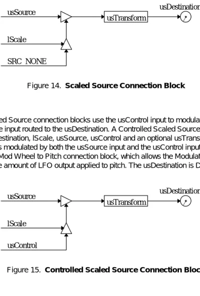
Scaled Source connection blocks scale the usSource input routed to the usDestination. A Source Scale connection block consists of usDestination, lScale, usSource, and an optional usTransform. The usControl input is set to SRC_NONE. The result is a signal which is modulated by the usSource input and applied to the usDestination. An example of this is the EG2 to Pitch connection block, the amount of modulation applied to pitch from the Pitch Envelope. The usDestination is DST_PITCH. usSource SRC NONE usDestination usTransform Σ lScale
Figure 14. Scaled Source Connection Block
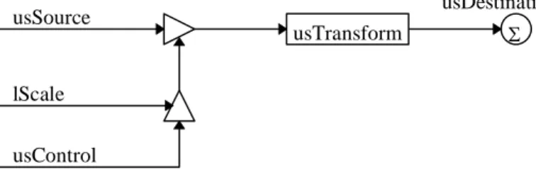
Controlled Scaled Source connection blocks use the usControl input to modulate or control the scaled usSource input routed to the usDestination. A Controlled Scaled Source connection consists of usDestination, lScale, usSource, usControl and an optional usTransform. The result is a signal which is modulated by both the usSource input and the usControl input. An example of this is the LFO Mod Wheel to Pitch connection block, which allows the Modulation Wheel (CC1) to determine the amount of LFO output applied to pitch. The usDestination is DST_PITCH.
usSource
usControl
usDestination
usTransform Σ
lScale
Figure 15. Controlled Scaled Source Connection Block
Connection Block Sources
Level 1 Connection Block sources generate control signals for use by Connection Block destinations:
Generic Sources
CONN_SRC_NONE No Source
CONN_SRC_LFO Low Frequency Oscillator CONN_SRC_KEYONVELOCITY Key on Velocity
CONN_SRC_KEYNUMBER Key Number
CONN_SRC_EG1 Envelope Generator 1
CONN_SRC_EG2 Envelope Generator 2
CONN_SRC_PITCHWHEEL Pitch Wheel MIDI Sources
CONN_SRC_CC1 Modulation Wheel
CONN_SRC_CC7 Channel Volume
CONN_SRC_CC10 Pan
CONN_SRC_CC11 Expression
CONN_SRC_RPN1 RPN1 - Fine Tune
CONN_SRC_RPN2 RPN2 - Coarse Tune
Note that the Gate signal is not included, because it is automatically required for all modules that use it. Likewise, the Sample Choice and Fine Tune outputs of the Note Routing logic are not standard modulation controls.
Connection Block Destinations
The Level 1 Connection Block destinations are: Generic Destinations CONN_DST_NONE No Destination CONN_DST_ATTENUATION Attenuation CONN_DST_PAN Pan CONN_DST_PITCH Pitch LFO DestinationsCONN_DST_LFO_FREQUENCY LFO Frequency
CONN_DST_LFO_STARTDELAY LFO Start Delay Time EG1 Destinations
CONN_DST_EG1_ATTACKTIME EG1 Attack Time CONN_DST_EG1_DECAYTIME EG1 Decay Time CONN_DST_EG1_SUSTAINLEVEL EG1 Sustain Level CONN_DST_EG1_RELEASETIME EG1 Release Time
EG2 Destinations
CONN_DST_EG2_ATTACKTIME EG2 Attack Time CONN_DST_EG2_DECAYTIME EG2 Decay Time CONN_DST_EG2_SUSTAINLEVEL EG2 Sustain Level CONN_DST_EG2_RELEASETIME EG2 Release Time
Connection Block Controls
The Level 1 Connection Block controls are: MIDI Controls
CONN_SRC_CC1 Modulation Wheel
CONN_SRC_RPN0 RPN0 - Pitch Bend Range
Connection Block Transforms
The Level 1 Connection Block destinations are: Transforms
CONN_TRN_NONE No Transform
CONN_TRN_CONCAVE Concave Transform
Connection Graph
The Connection Graph illustrates all of the required articulation modules, connection blocks and MIDI controllers/inputs connected to the Control Logic and Digital Audio Engine portions. This is the necessary architecture to perform one voice in a Level 1 synthesizer.
The Control Logic module translates MIDI note and sustain events into region/sample choice and associated control signals, including Key (the note number), Velocity (note emphasis), and Gate. Gate defines the start and end times of the note, and is used to trigger modulators, such as the LFO and envelope generators. In a higher level implementation, Gate may also be used to set the loop status in the digital oscillator.
The digital oscillator unit plays the sample. It is primarily controlled by the Pitch Sum node which accumulates signals from modulation sources to deliver the final pitch for the instrument. The digitally controlled amplifier takes the output of the digital oscillator and sets the volume. It is controlled by two signals: the Volume Sum node, which accumulates signals from modulation sources to deliver the final volume of the instrument, and the MIDI pan signal, which sets the stereo position of the stereo digital output.
Control signals from MIDI modulation sources, such as Volume and Pitch Bend, flow through connectors which use their attenuation values and transforms to define the range of the control. The Volume Sum node (DST_ATTENTION) can be looked at as a summing node if signals are represented in dB units, or as a multiplier if signals are represented in linear units. 0dB is defined as the maximum output level at the Volume summing node (DST_ATTENTION). For example, the output of the summing node expressed in terms of linear gain can be expressed as follows:
output = MIDI Volume * MIDI Expression * Velocity * EG1 * Sample Attenuation * AM
In the special case where the MIDI Mod Wheel signal controls the depth of the LFO output signal to either pitch or volume, the connector has an additional modulation input.
r l DCA Control Logic Sustain Pitch Whl Mod Wheel RPN 1&2 Volume Expression Note Digital Oscillator + Envelope Generator 1 Envelope Generator 2 LFO + MIDI In Audio Out DST_PAN DST_PITCH DST_ATTEN Sample choice sFineTune Gate Vel Key Cid 6 Cid 24 Cid 4 Cid 23 Cid 18 Cid 17 Cid21 Cid20 Cid12 Cid11 Cid 22 lAttenuation Pan RPN 0 Cid 27 Cid 25 Cid 28, 29 Cid 26 Cid 5 Cid 3 CC121,123
Figure 16. Connection Graph
Modulation Routing
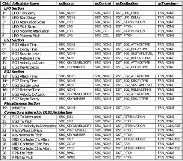
The Level 1 synthesizer supports the connection blocks listed in the following table. Each connection lists a usSource, usControl, usDestination, and usTransform. Each is numbered to correspond with its Connection ID numbered box in the Connection Graph.
Cid# Articulator Name usSource usControl usDestination usTransform
LFO Section
1* LFO Frequency SRC_NONE SRC_NONE DST_LFO_FREQ TRN_NONE
2* LFO Start Delay SRC_NONE SRC_NONE DST_LFO_DELAY TRN_NONE
3* LFO Attenuation Scale SRC_LFO SRC_NONE DST_ATTENUATION TRN_NONE
4 LFO Pitch Scale SRC_LFO SRC_NONE DST_PITCH TRN_NONE
5 LFO Modw to Attenuation SRC_LFO SRC_CC1 DST_ATTENUATION TRN_NONE
6 LFO Modw to Pitch SRC_LFO SRC_CC1 DST_PITCH TRN_NONE
EG1 Section
7* EG1 Attack Time SRC_NONE SRC_NONE DST_EG1_ATTACKTIME TRN_NONE
8* EG1 Decay Time SRC_NONE SRC_NONE DST_EG1_DECAYTIME TRN_NONE
9* EG1 Sustain Level SRC_NONE SRC_NONE DST_EG1_SUSTAINLEVEL TRN_NONE
10* EG1 Release Time SRC_NONE SRC_NONE DST_EG1_RELEASETIME TRN_NONE
11 EG1 Velocity to Attack SRC_KEYONVELOCITY SRC_NONE DST_EG1_ATTACKTIME TRN_NONE
12 EG1 Key to Decay SRC_KEYNUMBER SRC_NONE DST_EG1_DECAYTIME TRN_NONE
EG2 Section
13* EG2 Attack Time SRC_NONE SRC_NONE DST_EG2_ATTACKTIME TRN_NONE
14* EG2 Decay Time SRC_NONE SRC_NONE DST_EG2_DECAYTIME TRN_NONE
15* EG2 Sustain Level SRC_NONE SRC_NONE DST_EG2_SUSTAINLEVEL TRN_NONE
16* EG2 Release Time SRC_NONE SRC_NONE DST_EG2_RELEASETIME TRN_NONE
17 EG2 Velocity to Attack SRC_KEYONVELOCITY SRC_NONE DST_EG2_ATTACKTIME TRN_NONE
18 EG2 Key to Decay SRC_KEYNUMBER SRC_NONE DST_EG2_DECAYTIME TRN_NONE
Miscellaneous Section
19* Initial Pan SRC_NONE SRC_NONE DST_PAN TRN_NONE
Connections inferred by DLS1 Architecture
20 EG1 To Attenuation SRC_EG1 SRC_NONE DST_ATTENUATION TRN_NONE
21 EG2 To Pitch SRC_EG2 SRC_NONE DST_PITCH TRN_NONE
22 Key On Velocity to Attenuation SRC_KEYONVELOCITY SRC_NONE DST_ATTENUATION TRN_CONCAVE
23 Pitch Wheel to Pitch SRC_PITCHWHEEL SRC_RPN0 DST_PITCH TRN_NONE
24 Key Number to Pitch SRC_KEYNUMBER SRC_NONE DST_PITCH TRN_NONE
25 MIDI Controller 7 to Atten. SRC_CC7 SRC_NONE DST_ATTENUATION TRN_CONCAVE
26 MIDI Controller 10 to Pan SRC_CC10 SRC_NONE DST_PAN TRN_NONE
27 MIDI Controller 11 to Atten. SRC_CC11 SRC_NONE DST_ATTENUATION TRN_CONCAVE
28 RPN1 to Pitch SRC_RPN1 SRC_NONE DST_PITCH TRN_NONE
29 RPN2 to Pitch SRC_RPN2 SRC_NONE DST_PITCH TRN_NONE
Table 1 - Connection Block Table
(*Note: Scaled connection blocks are not shown on the connection graph.)
The articulation configuration is designed to expand into future specification levels in two ways. First, each module defines a base level set of controls and connectors. We expect most modules will expand as more controls and connections are added in the future. Secondly, the number of connection blocks will also grow as we add more articulation modules, control inputs, and required connections.
The following table shows the Minimum, Maximum and Unit values for each connection block of the DLS Level 1 synthesis architecture.
Articulator Default Value Min Value Max Value Units
LFO Section
LFO Frequency 5 Hz 0.1 Hz 10 Hz 32 bit pitch cents
LFO Start Delay 0.01 Secs 0.01 secs 10 secs 32 bit time cents
LFO Attenuation Scale 0 dB 0 dB 12 dB 32 bit gain (cB)
LFO Pitch Scale 0 cents -1200 cents 1200 cents 32 bit pitch cents
LFO Mod Wheel to Attenuation 0 dB 0 dB 12 dB 32 bit gain (cB)
LFO Mod Wheel to Pitch 0 cents -1200 cents 1200 cents 32 bit pitch cents
EG1 Section
EG1 Attack Time 0 secs 0 secs 20 secs 32 bit time cents
EG1 Decay Time 0 secs 0 secs 40 secs 32 bit time cents
EG1 Sustain Level 100 % 0% 100% 0.1 % units
EG1 Release Time 0 secs 0 secs 20 secs 32 bit time cents
EG1 Velocity to Attack 0 secs 0 secs 20 secs 32 bit time cents
EG1 Key to Decay 0 secs 0 secs 20 secs 32 bit time cents
EG2 Section
EG2 Attack Time 0 secs 0 secs 20 secs 32 bit time cents
EG2 Decay Time 0 secs 0 secs 40 secs 32 bit time cents
EG2 Sustain Level 100% 0% 100% 0.1 % units
EG2 Release Time 0 secs 0 secs 20 secs 32 bit time cents
EG2 Velocity to Attack 0 secs 0 secs 20 secs 32 bit time cents
EG2 Key to Decay 0 secs 0 secs 20 secs 32 bit time cents
EG2 to Pitch 0 cents -1200 cents 1200 cents 32 bit pitch cents
Miscellaneous Section
Initial Pan 0% -50% 50% 0.1% units
Table 2 - DLS Level 1 Default, Minimum, Maximum and Unit Values for Connection Blocks
Any unspecified connection block in a connection block list is set to its default value by the DLS Level 1 synthesis engine.
Data Objects
This section covers in greater depth the data and objects contained within an instrument. Because extensibility is important to the growth of the Downloadable Sounds specification, it is important to ensure that samples designed for the Level 1 specification will work in future Level specifications as well. The Level 2 specification must be an addition to the Level 1 specification that extends it without contradicting it or rewriting it.
To ensure such future compatibility, the specification follows these guidelines:
! Use 32-bit numbers for data formats, unless genuinely pointless.
! Define data structures in a chunked, expandable file format. Additional controls will be appended to existing objects as needed in future specifications.
! Allow for new structures to be added to the format.
! Design with backwards and forwards compatibility always in mind. Please refer to the DLS Level 1 File Format for more detail.
Object Hierarchy
A view of the hierarchy of objects in a Level 1 instrument helps demonstrate the relationships between objects. Melodic Instrument Global Connection Blocks Region (1..16) Wave Link Wave Sample Wave File
Wave Sample (optional)
Wave Data
This shows how a melodic instrument is composed of one global articulation set and up to sixteen regions managing up to sixteen samples.
The Drum Kit is a special case because it can have up to 128 matched pairs of drum sample/regions and articulations.
Drum Kit
Region (1..128)
Wave Link
Wave Sample
Wave File
Wave Sample (optional)
Wave Data
Region Articulation
All structures can be completely contained within the parent structure, with the exception of the Wave Data structure which should not be embedded within a Region. Instead, it should be
referred to by the Region. In this way, one sample can be used in multiple places. In fact, a sample should be accessible from more than one Instrument.
Please refer to the DLS Level 1 File Format for more detail.
Data Formats
A Downloadable Sound can contain information in one or more of the following formats. Cent 1/100th of a semitone.
Time Cents Time Cents, a signed 32-bit integer, represents time in a fractional logarithmic form. Since it is impossible to represent zero in this format, the value 8000000h has been chosen to denote an absolute zero. When the value 80000000h is applied to a destination, that destination cannot be modified by other sources; it will always be zero.
To convert from seconds to Time Cents, use the following formula:
(
)
Time Cents
=
log
2time
secs×
1200
×
65536
To convert from Time Cents to seconds, use the following formula:
Time
s tc sec=
× 2
1200 65536Pitch Pitch, a signed 32-bit integer, represents tuning in a logarithmic scale based on 1/65,536th of a cent.:
Absolute tuning is determined by the following formula:
Pitch
=
×
f
+
1200
×
440
6900
65536
2log
where f is the frequency.Relative tuning is determined by the following formula:
Pitch
f
F
=
1200
×
65536
×
log
2
where f is the frequency of interest and F is the reference frequency. Attenuation A signed, 32-bit integer, is a relative measure of attenuation in fractions of a
decibel, where each unit is 1/655,360th of a dB. Since it is impossible to
represent infinite attenuation in this format, the value 8000000h has been chosen to denote infinite attenuation. When the value 80000000h is applied to a
destination, that destination cannot be modified by other sources; it will always be infinite attenuation. Attenuation is calculated by the following formula:
attenuation
V
v
dB=
×
×
200
65536
log
10Sample Frequency A 32-bit unsigned integer, with the frequency specified in 1/1000th of Hertz.
Integer A 32-bit value used for counting, indexing into samples, and so on.
Instrument
A Level 1 Instrument can be either a Drum Kit or Melodic Instrument. The instrument header determines the number of regions in an instrument as well as its bank and program numbers. If the instrument is Melodic, it can have up to 16 regions and one set of Global Articulation data. If it is Drum Kit, it can have up to 128 regions and sets of articulation data, one for each drum. cRegions Specifies the count of regions for this instrument.
Locale Specifies the MIDI locale(Bank and Program Change) for this instrument.
Region
The Region is used by the Control Logic to decide which sample to use. Each region provides velocity and key number ranges to match against an incoming note. If these match, the sample is chosen for performance with the articulation and loop data selected by the region. The Region chunk also contains the Wave Link chunk and may contain articulation data (for Drum
Instruments only in Level 1).
Although the field has been provided, Level 1 does not support velocity cross switching. In Level 1, one instrument is only one sound; no layering is supported other than by using separate MIDI channels.
RangeKey Specifies the key range for this region. RangeVelocity Specifies the velocity range for this region.
fusOptions Specifies flag options for the synthesis of this region. The only flag defined at this time is the Self Non Exclusive flag. See Note Exclusivity section for more detail. usKeyGroup Specifies the key group for a drum instrument. Key group values allow multiple
regions within a drum instrument to belong to the same “key group.” If a synthesis engine is instructed to play a note with a key group setting and any other notes are currently playing with this same key group, the synthesis engine should turn off all notes with the same key group value as soon as possible. Valid values are:
0 No Key group 1-15 Key groups 1 to 15.
All Others Reserved
Wave Link
The Wave Link contains the link to the sample data. This was isolated from the region to allow for synthesis methods other than wavetable synthesis. The sample data is indexed through the Pool Table and the other fields provide the information to phase-lock multiple samples together to create stereo or even surround-sound images.
ulChannel Specifies the channel placement of the file. This is used to place mono sounds within a stereo pair or for multi-track placement. Each bit position within the ulChannel field specifies a channel placement with bit 0 specifying a mono file or the left channel of a stereo file. Bit 1 specifies the right channel of a stereo file. ulTableIndex Specifies the 0 based index of the cue entry in the wave pool table. See the DLS
Level 1 File Format document for information on the Pool Table.
Articulation
The Articulation data specifies a number of flexible connections for routing signals in the synthesizer. The Level 1 Device Architecture places a restriction on which connections are valid for a Level 1 Device. The chunk specifies the number of connections, followed by a list of connections.
cConnectionBlocks Specifies the number (count) of ConnectionBlocks that are contained in the articulator chunk.
usSource Specifies the source for the connection.
usControl Specifies the control for the connection. usDestination Specifies the destination for the connection usTransform Specifies the transform used for the connection. lScale Specifies the scaling value used for the connection.
Wave Sample
The Wave Sample chunk contains the low level parameters for playing a sample. Normally it is contained within the Wave chunk itself, but may also be used at the Region level to override loop points or other parameters.
usUnityNote Specifies the MIDI note which will replay the sample at original pitch. This value ranges from 0 to 127 (a value of 60 represents Middle C, as defined by the MMA).
sFineTune Specifies the tuning offset from the usUnityNote in 16 bit relative pitch.
lAttenuation Specifies the attenuation to be applied to this sample in 32 bit relative gain. This is used primarily to balance multi-sample splits.
fulOptions Specifies flag options for the digital audio sample. Flags are defined for disabling 16 bit to 8 bit truncation of samples and compression of samples by the driver. cSampleLoops Specifies the number (count) of loop records that are contained in the wave
sample chunk. One shot sounds will have the cSampleLoops field set to 0. ulLoopType Specifies the loop type. Only a forward loop is defined.
ulLoopStart Specifies the start point of the loop in samples as an absolute offset from the beginning of the data in the 'data' chunk of the wave file.
Minimum requirements
Except where noted, all specifications and features in this document are requirements for DLS Level 1. However, the following items are significant enough to warrant special mention:
! The hardware must have enough memory to support 256K words of sample memory (512 KB organized as 16-bit samples). After allowing for storage overhead in the device, the minimum number of sample words available for download is 240K samples.
! The hardware must be capable of supporting a minimum of 128 instruments, 128 sets of articulation data, 128 regions, and 128 samples at once. These may be used in the melodic instruments, drum kits or both.
! If a device claims support for both Level 1 and General MIDI, it must be able to support both of them simultaneously.
! 22.05 kHz is the minimum output sample rate of the DLS Level 1 synthesis engine.
! The hardware must support a minimum of 24 simultaneous voices.
Implementation Notes
This section contains technical advice for engineers implementing Level 1 devices in hardware or software.
! When a device supports both Level 1 and General MIDI, the device may share MIDI channels between Level 1 and General MIDI. In such a device, it will not be possible to use the General MIDI drum kit and the Level 1 drum kit simultaneously.
! Level 1 Devices do not support the use of the Coarse Tuning RPN on MIDI Channel 10.
Device Driver Design Notes
This section contains information for software engineers creating device drivers for the specification.
! If the device driver uses system memory for storage, it should allocate enough memory to satisfy the minimum Level 1 device requirements while it is being loaded. If it is unable to allocate the minimum amount of memory, it should report an error to the user and remove itself.
! The device driver model should include an inquiry to allow the application to determine if a Level 1 device also supports General MIDI.
! The Level 1 device driver supports only exclusive access to a Level 1 device. When a device is opened for exclusive access by an application, no other application can use that device until the application closes the device. Level 2 device drivers will address the issue of shared access of the device.
Application Design Notes
This section contains information for software engineers creating applications for use with Level 1 devices.
! Ap