Adaptive Position Tracking Control of a BLDC Motor
using a Recurrent Wavelet Neural Network
Chun-Fei Hsu1 Chih-Min Lin2* Chao-Ming Chung2
1Department of Electrical Engineering, Chung Hua University, Hsinchu, 300, Taiwan, Republic of China 2Department of Electrical Engineering, Yuan Ze University, Chung-Li, Tao-Yuan, 320
Taiwan, Republic of China
Abstract: The recurrent wavelet neural network (RWNN) has the advantages such as fast learning property, good
generalization capability and information storing ability etc. Based on these advantages of RWNN, an adaptive position tracking control (APTC) system, which is composed of a neural controller and a robust controller, is proposed in this paper. The neural controller uses the RWNN structure to online mimic an ideal controller, and the robust controller is designed to achieve tracking performance with desired attenuation level. The adaptive laws of APTC system are derived based on the Lyapunov stability theorem and gradient decent method. Finally, the proposed APTC method is applied to a brushless DC (BLDC) motor. The hardware implementation of APTC scheme is developed on a field programmable gate array (FPGA) chip. Experimental results verify that a favorable tracking response can be achieved by the proposed APTC method even under the change of position command frequency after training of RWNN.
Keywords: Adaptive control, recurrent neural network, wavelet neural network, BLDC,
1. INTRODUCTION
With the learning ability of neural network, neural networks have widely been recognized as a powerful tool in industrial contr ol, commer cial prediction, image processin g applications and etc. (Mendel, 1994). The characteristics of fault tolerance, parallelism and learning suggest that they may be good candidates for implementing real-time adaptive control for unknown nonlinear dynamic systems (Omidvar and Elliott, 1997). The successful key element is the approximation ability of neural network, where the parameterized neural network can approximate an unknown system dynamics through some learning algorithms. Many authors have hinted the neural networks as powerful building blocks for a wide class of complex nonlinear system control strategies when there exists no complete model information or a controlled plant is considered as a “black box” (Hsu et al., 2005; Leu et al., 2005; Polycarpou, 1996; Tang et al., 2006).
Recently, some researchers have developed the structure of neural network based on the wavelet functions to construct the wavelet neural network (WNN) (Billings and Wei, 2005; Zhang, 1997). Unlike the sigmoidal functions used in conventional neural networks, wavelet functions are spatially localized, so that the learning capability of WNN is more efficient than the conventional sigmoidal function neural network for system identification. The training algorithms for WNN typically converge in a smaller number of iterations than for the conventional neural networks (Zhang, 1997). Up to now, there has been considerable interest in exploring
the applications of WNN to deal with nonlinearity and uncertainties of real-time adaptive control system (Hsu et al., 2006; Lin, 2002; Sousa et al., 2002). These WNN-based adaptive neural controllers combine the capability of neural networks for learning ability and the capability of wavelet decomposition for identification ability.
Although the control performances are acceptable in (Hsu et al., 2005; Hsu et al., 2006; Leu et al., 2005; Lin, 2002; Sousa et al., 2002; Tang et al., 2006), these neural networks are feedforward neural networks belonging to static mapping networks. Without aid of tapped delay, a feedforward neural network is unable to represent a dynamic mapping. In addition, the neural network must be selected with a sufficiently large number of neurons in the hidden layer, which consumes a large amount of processing time for real-time applications (Juang et al., 2007; Lin and Lee, 1996). According to the structure, the recurrent neural network has superior capabilities as compared to feedforward neural networks, such as their dynamic response and their information storing ability. Since the recurrent neural network captures the dynamic response of a system, the network model can be simplified (Lin and Lee, 1996).
This paper proposes a recurrent wavelet neural network (RWNN), which has superior capability to the conventional WNN in an efficient learning mechanism and dynamic response. Temporal relations are embedded in RWNN by adding feedback connections, so that the RWNN provides a dynamical mapping. Then, an adaptive position tracking control (APTC) system using RWNN approach is proposed
to tackle the control problem of the brushless DC (BLDC) motor, which is ideal for use in expensive environments such as aeronautics, robotics, electric vehicles and dynamic actuation. All the parameters of the proposed APTC system are online tuned in the Lyapunov sense and gradient decent, thus th e stability of th e closed-loop system can be guar an teed. Finally, the proposed APTC system is implemented on a field programmable gate array (FPGA) chip for possible low-cost and high-performance industrial applications. The experimental results demonstrate that the proposed APTC scheme can achieve favorable position tracking control for the BLDC motor even under the change of position command frequency. Moreover, the better tracking performance can be achieved as a specified attenuation level is chosen smaller.
2. PROBLEM STATEMENT OF BLDC MOTOR
During two decade years, brushless DC (BLDC) motors have gained widespread use in electric drivers. BLDC motors are ideal for use in expensive environments such as aeronautics, robotics, electric vehicles and dynamic actuation (Dote and Kinoshita, 1990). Unfortunately, the BLDC motor is a nonlinear system whose internal parameter values will change slightly with different input comman d and environmen ts. Using these BLDC motors in h igh-performance drivers require advance and robust control methods. The system equations of BLDC motor driver in a d-q model can be expressed as (Rubaai et al., 2002; Rubaai et al., 2007). 1 s d m qs qs r ds qs r q q q q R L i i i v L L L L � � � � � � � � (1) 1 q s ds ds r qs ds d d d L R i i i v L L L � � � � � (2) Lq = Lis + Lmq (3) Ld = Lis + Lmd (4)
where ids and iqs represent the d and q axes stator currents, respectively, Vds and Vqs are the d and q axes stator voltage, respectively, Ld and Lq are the d and q axes stator inductances, respectively, Rs is the stator resistance, Lis is the stator leakage inductance, Lmd and Lmq are the d and q axes magnetizing inductances, respectively, �r is the electrical rotor angular velocity, and �m is the flux linkage of permanent magnet. The torque equation is expressed as (Rubaai et al., 2007).
2 2
r r e L
J B T T
N� �� N� � � (5)
where N is the number of poles, J is the inertia of the rotor, B is the damping coefficient, Te is the electromagnetic torque and TL is the load disturbance. By using the field-oriented control, the electromagnetic torque of BLDC motor driver can be expressed as (Slotine and Li, 1991).
3 2 2 e m qs t qs N T � � i �k i (6) where 3 2 2 t m N
k � � is the constant gain. From (5) and (6), the system dynamic equation can obtain
f gu h � � � � � �� � (7) wh er e � is a position of rotor, , , 2 t k B N f g J J � � � , 2 L N h T J
� � and u = iqs is the control effort. The control objective of BLDC motor is to find a control law so that the rotor position � can track the position command �c closely. Define the tracking error as
e = �c – � (8)
Assume that all the parameters in (7) are well known, there exits an ideal controller (Slotine and Li, 1991).
* 1
1 2
( c )
u �g� � � � � � �f� h �� k e��k e (9) where k1 and k2 are non-zero positive constants. Applying the ideal controller (9) into (7), it is obtained that
1 2 0
e�k e�k e�
�� � (10)
If k1 and k2 are chosen to correspond the coefficients of a Hurwitz polynomial, it implies that limt��e�0 for any starting initial conditions. Since the system dynamics and the load disturbance may be unknown or perturbed in practical applications, the ideal controller u* in (9) can not be precisely obtained.
Much resear ch has been done to apply various approaches in the control field of BLDC motor (Liu et al., 2005; Rubaai et al., 2002; Rubaai et al., 2007). A PI controller is proposed based on the completely understanding of the model and through some time-consuming design procedures; however, their performances generally depend on the working point, thus the control parameters which want to ensure proper behavior in all operating conditions are difficult to design (Liu et al., 2005). Rubaai et al. (2002) proposed an adaptive fuzzy controller. In order to ensure the system stability, a compensation controller will be designed to dispel the approximation error. However, the most frequently used of compensation controller is like a sliding-mode control, which requires the bound of the approximation error. To solve this chattering problem, a robust adaptive fuzzy-neural-network controller had been developed (Rubaai et al., 2007). Though the robust tracking performance can be achieved, the used neural network is a feedforward neural network. It may be selected with a sufficiently large number of hidden neurons, in which the computation loading is heavy.
3. APTC DESIGN 3.1. Description of RWNN
As shown in Fig. 1, the RWNN, is comprised of an input layer, a mother wavelet layer, a product layer and an output layer, is adopted to implement the neural controller. The RWNN output can perform the mapping according to
1 1 1 ( ) M M L j j j ij ij i j j y z � � � �
�
� � �� �
� � (11)where the subscript ij indicates the ith input term of the jth wavelet, �j is the connection weight between the product nodes and output node, and ( p ).
ij ij i ij ij ij
z � � x � � r �m The �
ij, mij and rij are the dilation factor, translation factor and
recurrent factor, respectively, and the memory term �ijp is
the self-recurrent term of a wavelet. In addition, the mother wavelets are chosen as
2 2 2
( ) (1 ) exp( ).
ij zij zij zij
� � � � � (12)
For ease of notation, (11) can be expressed in a compact vector form as
y(x, , m, r) = T�(x, , m, r) (13)
where x = [x1 x2 ... xL]T is the input vector, � = [�
1�2 ... �M] T, �= [�1�2 ... �M]T, = [� 11 ... �L1�12 ... �L2 ... �1M ... �LM] T, m = [m11 ... mL1 m12 ... mL2 ... m1M ... mLM]T and r = [r 11 ... rL1
r12 ... rL2 ... r1M ... rLM]T. The architecture of the RWNN
used in this paper is designed to keep the advantage of simple structure and to consider the dynamic characteristics. The meaning of the recurrent network is to consider the past output of translation layer in the input space since the input of translation layer is related to its output. Thus, the RWNN has dynamic characteristics.
3.2. Design of APTC System
This study proposes an adaptive position tracking control (APTC) system as shown in Fig. 2, where the control law is designed as
Figure 1: The Architecture of RWNN
Figure 2: The Block Diagram of APTC System for BLDC Motor
uac = unc + urb (14)
in which a sliding surface is defined as 1 2 0 ( ) .
t
s� �e� k e�k
�
e� �d (15) The neural controller unc uses a RWNN to online approximate the ideal controller in (9), and uses a robust controller urb is designed to achieve L2 tracking performance with desired attenuation level. Substituting (14) into (7) and using (15), the error dynamic equation can be obtained as*
1 2 ( nc rb) .
e�k e�k e�g u �u �u �s
�� � � (16)
According to the approximation theory, there exists an optimal RWNN approximator to approximate the ideal controller, which is denoted as (Billings and Wei, 2005).
u* = *T� + � (17)
where � denotes the approximation error and * is the optimal parameter vector of . In fact, the optimal parameter vector for neural network to approximate the ideal controller u* is difficult to determine. To solve this difficulty, an estimative parameter vector is required to estimate the optimal value, and the neural network with estimative parameter vector is
ˆT nc
u � (18)
where ˆ is the estimative parameter vector of �. Then the estimative error between ideal controller and neural controller is defined as
* *T ˆT T
nc
where � � *� ˆ . Substitute equation (19) into equation (16) can obtain
( T ).
rb
s��g � � � �u (20)
In case of the existence of �, consider a specified L2 tracking performance (Lin and Lin, 2002; Wang et al., 2002; Yang and Wang, 2007)
2 2 2 2 0 0 1 (0) T(0) (0) T s T s dt dt g � � � � � � � �
�
� ��
(21)where �1 is a positive constant. If the system starts with initial con dition s s(0) = 0 an d �(0)�0,th e L2 tr ackin g performance in (21) can be rewritten as
2[0, ] sup L T s �� � � � (22) where 2 2 0 T s �
�
s dt and 2 2 0 . T dt � ��
� The attenuation constant � can be specified by the designer to achieve desired attenuation ratio between and || s | and | � ||. If � = � , this is the case of minimum error tracking control without disturbance attenuation. To guarantee the stability of the APTC system, the Lyapunov function candidate is defined as2 1 1 . 2 2 T g V � s � � � � (23)
Taking the derivative of Lyapunov function in (23) and using (20), yields V� = 1 T g ss� � � �� � = 1 ˆ ( � � � )� � � �T �T rb g sg u = 1 ˆ ( ). � �� � � � � �� � � � � � � �T rb g s sg u (24)
If the parameter tuning law is chosen as 1
ˆ � �s
� (25)
and the robust controller is chosen as urb = 2 2 1 2 s � � � (26)
then (24) can be rewritten as V� = 2 2 2 1 2 g s�� � ���� �� ��s �� � � � � = 2 2 2 2 1 1 2 2 2 s s g � � � � � � � �� � � � � � � � � � � � � � � � 2 2 2 1 2 2 s g��� � � � �� � �. (27) Assume �� L2[0, T], �T � [0, �], integrating (27) from t = 0 to t = T, yields 2 2 2 0 0 1 1 ( ) (0) . 2 2 T T V T �V � � g
�
s dt� g��
� dt (28) Since V(T) � 0, the above inequality implies the following inequality 2 2 2 0 0 1 1 (0) . 2 2 T T g�
s dt�V � g��
� dt (29) Using (23), (29) is equivalent to (21). Since V(0) is fin ite, if th e appr oximation err or � � L2, th a t is2
0 ( ) ,
t
t dt
� � �
�
using the Barbalat’s lemma (Slotine and Li, 1991), the APTC system is stable with L2 tr acking performance in Lyapunov sense.3.3. Full-tuned Online Learning Laws
Although the parameter tuning law in previous sub-section can modify the weights of output layer to the optimal values, the performance and converge speed are still affected by the parameter vectors in translation layer. If the variances, means and recurrent weights in translation layer are selected in appropriate value, the network will converge at high speed as well as high performance. However, the optimal values of parameter vectors in translation layer are not easy to find. In order to get the optimal parameter values of translation layer, the online tuning laws which are derived by Lyapunov function and gradient decent method are proposed to tune these parameters. To obtain the online tuning laws, first, the adaptive law in equation (25) can be rewritten as
1 ˆj s j
� � � �� (30)
According to gradient decent method, this adaptive law can also be presented as
1 1 ˆ ˆ j j j V u V u u � � � � � �� � �� � � �� � � (31) Comparing equation (31) with equation (30), the Jacobian term of the controlled system can be obtained as
. V s u � � �
� Therefore, the online tuning laws of variances, means and recurrent weights can be presented as
ij �� = 2 ˆ 2 ˆ ij j ij V u V u u u � � � � �� �� � �� � �� � �� �� = 2 2 2 2 2 2 2 2 ( ) ˆ 2 ( ) 1 ( ) p ij i ij ij ij p j j p ij i ij ij ij ij i ij ij ij w x r m s x r m w x r m �� � � � � � � � � � � � � � � � � � � � � � � � � (32) 3 3 ˆ j ij ij j ij V u V u m u m u m �� � � � � � �� � �� � � � �� � �
2 2 2 3 2 2 2 2 ( ) ˆ 2 ( ) 1 ( ) p ij i ij ij ij p j j p ij i ij ij ij ij i ij ij ij w x r m s x r m w x r m � � � � � � � � � � � � � � � � � � � � � � � � � (33) 4 ˆ 4 ˆ ij ij j ij V u V u r u r u r � � � � �� � �� � �� � � � �� � � 2 2 2 4 2 2 2 2 ( ) ˆ 2 ( ) 1 ( ) p p ij ij i ij ij ij p p j j p ij ij i ij ij ij ij i ij ij ij w x r m s x r m w x r m �� � � � � � � � � � � � � � � � � � � � � � � � � � � (34) Apply these online tuning laws into RWNN, the parameters in translation layer can be tuned to appropriate values. Therefore, the convergence can still be at high speed even if inappropriate initial parameters are given.
4. EXPERIMENTAL RESULTS
This study used the Altera Stratix II series FPGA chip, the Altera Quartus II software, the Nios II processor, the Nios II Integrated Development Environment (IDE) and the verilog hardware description language to implement the hardware control system. Field programmable gate array (FPGA) is a fast prototyping IC component. This kind of IC in cor por ates th e ar chitectur e of a gate ar r ay an d programmability of a programmable logic device. The advantage of controller implement by FPGA includes shorter development cycles, lower cost, small size, fast system execute speed, and high flexibility. The Quartus II software is the development tool for programmable logic devices. The Nios II processor is a configurable, versatile, RISC embedded processor. It can be embedded into Altera FPGA, and allow designers to integrate peripheral circuits and processors in the same chip. Additionally, the PC-developed algorithm and C language program can be rapidly migrated to the Nios II processor to shorten the system development cycle. The Nios II IDE can be accelerates software development (http://www.altera.com).
The external peripheral interfaces are used to transmit and receive the motor driver signals including motor rotational direction control signal circuit, encoder signal circuit, and 12-bits D/A converter circuit. The motor rotational direction control signal circuit uses the operational amplifier IC to raise the motor rotational direction control voltage up from the FPGA. The encoder signal circuit raises the encoder signal voltage up from the motor driver. The 12-bits D/A converter IC with dual channel voltage output is used to control the BLDC motor. Additionally, every IC that connects with the FPGA chip uses asynchronous bus transceiver IC to protect the current reflow to FPGA chip. The experimental setup is shown in Fig. 3. The proposed control algorithm is realized in the Nios II programming interface. The software flowchart of the control algorithm is shown in Fig. 4. In the main program, the initialization of controller parameters is preceded. Next, the interrupt interval
for the interrupt service routine (ISR) with a 1msec sampling rate is set. Then, the controller sample times can be governed by the built-in timer, which generates periodic interrupts.
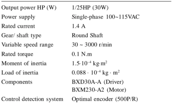
The BLDC motor system offers high performance and simple operation from a compact driver and motor. The specification s of the adopted BLDC motor system manufactured by the Orientalmotor Company are outlined in Table I (http://www.orientalmotor.com). Modern mechanical systems often require high-speed high-accuracy linear motions. These linear motions are usually realized using the rotary motors with a mechanical transmission. The command using alternating sinusoidal and alternating stepped can supply the different linear motion speed. A second-order transfer function with 0.3 sec rise time of the following form is chosen as the reference model for the periodic step command
2 2 2 2 400 2 40 400 n n n � � � � �� � � � � � � � (35)
where � is the Laplace operator, � is damping ratio (set at one for critical damping) and �n is undamped natural frequency. The periodic step command can be specified in the reference model to smooth the reference trajectory. Moreover, in the proposed control system, without the second-order reference model the control input at the beginning will be very large due to the tracking error in the control algorithm. In addition, when the command is a sinusoidal reference trajectory, the trajectory of sinusoidal command doesn’t need to change; therefore, the reference model is set as one.
First, an H� adaptive fuzzy tracking control system proposed in Ref. (Rubaai et al., 2007) is applied to BLDC motor. The experimental results of H� adaptive fuzzy tracking control are shown in Fig. 5. The tracking responses are shown in Figs. 5(a) and 5(d), associated control efforts are shown in Figs. 5(b) and 5(e); and tracking errors are shown in Figs. 5(c) and 5(f), due to a sinusoidal command and a periodic step command, respectively. From the experimental results, though the H� adaptive fuzzy tracking control can achieve tracking performances and there are no chattering phenomena in the control efforts; however, the convergence of the tracking error and controller parameters are very slow at beginning.
Then, the proposed APTC is applied to BLDC motor again. It should be emphasized that the development of APTC system does not need to know the system dynamics of the controlled system. For practical implementation, the parameters of the APTC system can be online tuned by the proposed adaptive laws without the need of system parameters. The control parameters for adaptive laws are chosen as k1 = k2 = 4, �1 = 0.02 and �2 = �3 = �4 = 0.0002. All the gains in the proposed control systems are chosen to achieve the best transient control performance in the considering the requirement of stability and possible
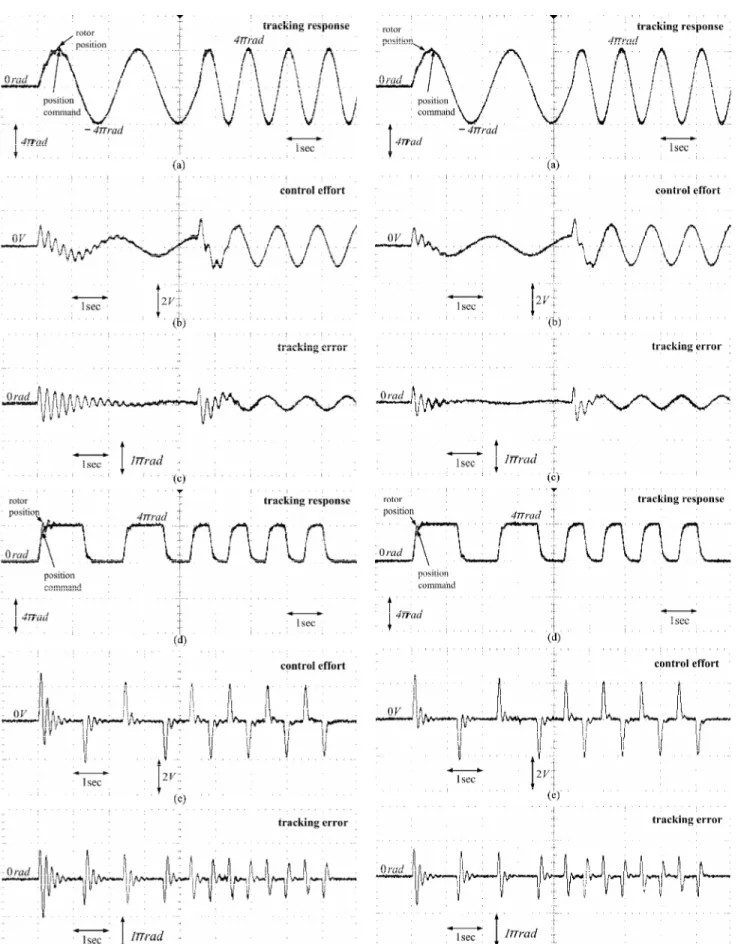
operating conditions. The experimental results of APTC with ��= 0.8 are shown in Fig. 6. The tracking responses are shown in Figs. 6(a) and 6(d); associated control efforts are shown in Figs. 6(b) and 6(e); and tracking errors are shown in Figs. 6(c) and 6(f) due to a sinusoidal command and a periodic step command, respectively. If a specified attenuation level � is chosen smaller, the experimental results of APTC with ��= 0.5 are shown in Fig. 7. The tracking responses are shown in Figs. 7(a) and 7(d); associated control efforts are shown in Figs. 7(b) and 7(e); and tracking errors are shown in Figs. 7(c) and 7(f) due to a sinusoidal command and a periodic step command, respectively. It is shown that the proposed Figure 3: The Experimental Setup
Figure 4: The Control Design Flow Chart
Figure 5: Experimental Results of H� Adaptive Fuzzy Tracking
step command, respectively. From the experimental results, it is seen that the tracking performance of the trained APTC is further improved when the initial values are trained, and they can achieve favorable robust characteristics for the command frequency variation.
5. CONCLUSIONS
This paper has successfully implemented an adaptive position tracking control (APTC) scheme for a brushless DC (BLDC) motor position tracking con trol on a field programmable gate array (FPGA) chip. Using the FPGA to implement, the APTC system can achieve the characteristics of small size, fast execution speed, less memory. Then, the effectiveness of the proposed APTC system is verified by some experimental results. The major contributions of this paper are: (1) the successful development of an APTC, in which the Lyapunov stability theorem and gradient decent is used to derive the online tuning algorithms. (2) the L2 tracking performance can be achieved with a desired attenuation level using the proposed learning mechanism. (3) the successful applications of APTC to control a BLDC motor. And, the proposed APTC methodology can be easily extended to other motors. (4) the FPGA implementation consumes less power, in terms of core IC power consumption an d especially in ter ms of the boar d-level power consumption, than the PC and DSP implementation.
Acknowledgments
The authors appreciate the partial financial support from the National Science Council of Republic of China under grant NSC 96-2218-E-216-001.
References
[1] Billings, S. A. and Wei, H. L., “A New Class of Wavelet Networks for Nonlinear System Identification,” IEEE Trans. Neural Networks, 16(4), 862-874, 2005. [2] Dote, Y. and Kinoshita, S., Brushless Servomotors:
Fundamentals and Applications, Clarendon Press Oxford, 1990.
APTC can achieve favorable tracking performance; moreover, the better tracking performance can be achieved as a specified attenuation level � is chosen smaller.
Further, the trained APTC is applied to the BLDC system again. The experimental results of trained APTC with ��= 0.5 are shown in Fig. 8. The tracking responses are shown in Figs. 8(a) and 8(d); associated control efforts are shown in Figs. 8(b) and 8(e); and tracking errors are shown in Figs. 8(c) and 8(f) due to a sinusoidal command and a periodic
Figure 8: Experimental Results of Trained APTC with � = 0.5
Table I
The Specifications of BLDC Motor System
Output power HP (W) 1/25HP (30W)
Power supply Single-phase 100~115VAC Rated current 1.4 A
Gear/ shaft type Round Shaft Variable speed range 30 ~ 3000 r/min Rated torque 0.1 N.m Moment of inertia 1.5�10–4 kg�m2 Load of inertia 0.088 � 10–4 kg � m2 Components BXD30A-A (Driver)
BXM230-A2 (Motor) Control detection system Optimal encoder (500P/R)
[3] Hsu, C. F., Lin, C. M. and Chen T. Y., “Neural-network-Identification-based Adaptive Control of Wing Rock Motion,” IEE Proc. Control Theory Appl., 152(1), 65-71, 2005.
[4] Hsu, C. F., Lin, C. M. and Lee, T. T., “Wavelet Adaptive Backstepping Control for a Class of Nonlinear Systems,” IEEE Trans. Neural Networks, 17(5), 1175-1183, 2006. [5] Juang, C. F. and Chung, I. F., “Recurrent Fuzzy Network Design using Hybrid Evolutionary Learning Algorithms,” Neurocomputing, 70(16), 3001-3010, 2007.
[6] Leu, Y. G., Wang, W. Y. and Lee, T. T., “Observer-based Direct Adaptive Fuzzy-neural Control for Nonaffine Nonlinear Systems,” IEEE Trans. Neural Networks,
16(4), 853-861, 2005.
[7] Lin, C. K., “Adaptive Tracking Controller Design for Robotic Systems using Gaussian Wavelet Networks,” IEE Proc. Control Theory Appl., 149(4), 316-322, 2002. [8] Lin, C. L. and Lin, T. Y., “Approach to Adaptive Neural Net-based H� Control Design,” IEE Proc. Control Theory Appl., 149(4), 331-342, 2002.
[9] Lin, C. T. and Lee C. S. G., Neural Fuzzy Systems: A Neuro-Fuzz y Synergis m to Intelligent Sys tems, Englewood Cliffs, NJ: Prentice Hall, 1996.
[10] Liu, Y., Zhu, Z. Q. and Howe, D., “Direct Torque Control of Brushless DC Drives with Reduced Torque Ripple,” IEEE Trans. Ind. Appl., 41(2), 599-608, 2005.
[11] Mendel, J. M., A Prelude to Neural Networks: Adaptive and Learning Systems, Englewood Cliffs, NJ: Prentice-Hall, 1994.
[12] Omidvar, O. and Elliott, D. L., Neural Systems for Control, New York: Academic, 1997.
[13] Polycarpou, M. M., “Stable Adaptive Neural Control Scheme for Nonlinear Systems,” IEEE Trans. Automatic Control, 41(3), 447-451, 1996.
[14] R ubaai, A., Ricketts, D. and Kankam, M . D., “Development and Implementation of an Adaptive Fuzzy-neural-network Controller for Brushless Drives,” IEEE Trans. Ind. Appl., 38(2), 441-447, 2002.
[15] Rubaai, A., Ofoli, A. R., Cobbinah, D., “DSP-based Real-time Implementation of a Hybrid H� Adaptive Fuzzy Tracking Controller for Servo-motor Drives,” IEEE Trans. Ind. Appl., 43(2), 476-484, 2007.
[16] Slotine, J. J. E. and Li, W. P., Applied Nonlinear Control, Englewood Cliffs, NJ: Prentice Hall, 1991.
[17] Sousa, C. D., Hemerly, E. M. and Galvao, R. K. H., “Adaptive Control for Mobile Robot using Wavelet Networks,” IEEE Trans. Systems Man Cybern. Part B,
32(4), 493-504, 2002.
[18] Tang, Y., Sun, F. and Sun, Z., “Neural Network Control of Flexible-link Manipulators using Sliding Mode,” Neurocomputing, 70(1), 288-295, 2006.
[19] Wang, W. Y., Chan, M. L., Hsu, C. C. J. and Lee, T. T., “H� Tracking-based Sliding Mode Control for Uncertain Nonlinear Systems via an Adaptive Fuzzy-neural Approach,” IEEE Trans. Systems Man Cybern. Part B,
32(4), 483-492, 2002.
[20] Yang, Y. S. and Wang, X. F., “Adaptive H� Tracking Control for a Class of Uncertain Nonlinear Systems using Radial-basis-function Neural Networks,” Neurocomputing, 70(4), 932-941, 2007.
[21] Zhang, Q., “Using Wavelet Network in Nonparametric Estimation,” IEEE Trans. Neural Networks, 8(2), 227-236, 1997.
[22] [Online] http://www.altera.com/ [23] [Online] http://www.orientalmotor.com/