© Penerbit UTHM
DOI: https://doi.org/10.30880/ijie.2018.10.05.019
Optimum Design of Nozzle Geometry of Dry Ice Blasting
Using CFD for the Reduction of Noise Emission
Mohamad Nur Hidayat Mat, Norzelawati Asmuin
*Faculty of Mechanical Engineering, Universiti Tun Hussein Onn, 86400 Parit Raja, Johor, Malaysia
Received 1 August 2018; Accepted 01 August 2018; Available online 30 October 2018
1. Introduction
Dry ice blasting is an environmentally–friendly Method. It is a form of carbon dioxide (CO2) cleaning process where dry ice, the solid form of CO2 is accelerated in a pressurized air stream and directed toward contaminated surfaces. The cleaning process of dry ice blasting is based on three combined mechanic isms which are thermal, mechanical and sublimation effect, see Fig. 1 for the three active mechanism of dry ice blasting. The thermal effect is due to differences in thermal coefficient between surface contaminant and substrate which cause brittle of contaminant. The mechanical effect is a result of the kinetic energy of the blasting medium which can reach supersonic speeds upon the surface impact. The sublimation effect occurs is due to the direct change of CO2 from the solid to the gaseous phase cause the volume increase of about 600-fold [1].
The basic advantages of dry ice blasting are relatively low abrasiveness of blasting medium and environmentally friendly as the blast media which is small pallets of CO2, immediately disappears upon impact and return to their natural state in the atmosphere producing little waste other than the contaminate being removed. In addition, carbon dioxide released from the dry ice blasting process is no new carbon dioxide released into the atmosphere, so it does not increase CO2 concentration in the atmosphere.
Fig. 1. Active mechanism of dry ice blasting [2]
Nozzle geometry plays an important role in optimizing the cleaning performance of pre-surface treatment [3]. The best novelty design of nozzle geometry provides superior particle passage due to its favorable convergent and divergent acceleration characteristic [4]. The size of expansion nozzles influences on the particle size, shape and velocity of dry ice particle. Furthermore, adding an expansion nozzle at the outlet of the nozzle can keep dry ice particle at a lower temperature. There were two stages of dry ice development inside the expansion nozzle. First, the temperature of dry ice jet decreases and approaches a stable temperature in the early stage and then moves to a second stabletemperature [5]. Then, the larger nozzle throat diameter corresponding to the low-pressure operation and large pellets impacting the surface with low flux density is an idea for soft cleaning. Besides, it was found that the jet angle affecting the feed speed, Abstract: Dry ice blasting has been used in the modern cleaning industry. However, the primary disadvantage of dry ice blasting is high noise exposure. At a high blasting pressure, the process reaches a harmful noise level of up to 130 dBA. The situation significantly impairs to a human being when the noise emission occurs in an inaudible frequency area. Present safety measures are only based on administrative control by encapsulating the entire system with sound insulation. The main objective of this project is to study the optimum nozzle configuration on the effect of dry ice blasting particle velocity and acoustic noise emission. Different nozzle geometry were simulated several times until optimization is achievable. Three-dimension models are designed using CATIA V5. Then the models are simulated with Ansys Fluent V18.2. The numerical studies have been carried out using density based, standard k- e turbulence and Acoustic Broadband Noise Sources model. Six (6) different nozzle configuration namely divergent length, the angle of particle inlet, convergent diameter, expansion ratio, gas inlet diameter and length ratio are analyzed in term of particle velocity magnitude and acoustic power level. The result shows that the optimum nozzle configuration for divergent length, the angle of particle inlet, convergent diameter, expansion ratio, gas inlet diameter and length ratio are 230 mm, 30 mm, 35 mm, 1.00, 6 mm and 0.80 respectively. This configuration provides minimum lowest acoustic noise emission and maximum particle velocity magnitude.
where the maximum feed speed increases from 70-90 degree. A perpendicular jet creates a hammer effect of the dry-ice jet, while smaller angles mean an increased abrasive effect of the process [6]. Since dry ice pellets are carried and accelerated by compressed air through a gun with nozzle application, many factors possibly influence the dry ice particle velocity in dry ice blasting, including dry ice nozzle configuration, accelerating gas conditions and dry ice properties. In addition, dry ice particle velocity increases significantly with the increase in nozzle divergent length, especially as the nozzle divergent length is 230 mm [7]. This result means that dry ice velocity cannot be sufficiently achieved within a short nozzle. When the nozzle divergent length is 230 mm, dry ice particle velocity increases gradually and even decreases slightly with a further increase in nozzle divergent length. Nozzle expansion ratio also has a significant effect on dry ice particle velocity. It is clearly seen that dry ice particle increases with increasing expansion ratio and reaches a maximum value when the expansion ratio is equal to 1.75 and then decreases with a further increase in nozzle expansion ratio. Therefore, the optimal expansion ratio is 1.75 from the point of view of dry ice particle velocity. Another important finding shows that geometry shape of the nozzle can give significant effect to the flow behavior. The biggest conical angle is the best shape to give the shortest time for fluid to travel [8] [4]. Apart from that, it has been found that the geometrical arrangement of nozzle geometry is an effective way to optimize noise reduction and cancellation [9]. However, it was found that none of all the researchers briefly explained the relationship between the nozzle geometry in term of particle inlet angle on the reduction of acoustic noise emission. Hence in this study, the nozzle geometry would be investigated to determine the relationship between the maximum particle velocity acoustic power levels on different particle inlet angle. It was found that the acoustic noise generated from the supersonic nozzle is a function of the jet velocity to a high power and the jet area which is predominantly from the exit of the nozzle [10]. However, it was found from the experimental result of identifying noise generation from dry ice blasting nozzle. They concluded that there were there three primary noise sources coming from dry ice blasting nozzle. Firstly, noise originates within the aperture area, where the compressed air jet impinges on the still air. The noise also emerges during the impact on the workpiece surface and above a certain blasting pressure in the free jet between the outlet edge and the workpiece surface [1]. This agreement had been supported where the noise levels may increase by up to 7 decibels when blasting an object with numerous pits or sharp edges and a concave, sound-focusing shape object. The nozzle includes the shape and surface texture of the surface being blasted, the amount of moisture present in the compressed air supply, the humidity of the day, and of course, the distance was influenced the noise generation. Pitted surfaces raise noise levels due to jet screech and whistle. High humidity raises noise levels due to better sound transmission than dry air, and also due to the
addition of moisture to the compressed air supply, which raises noise levels because the moisture is frozen into ice crystals and expelled with the blast stream. On the other hand, it was reported that there were a few techniques to reduce noise emission coming from the nozzle geometry that involves new nozzle design concepts such as chevrons, corrugations, beveled nozzles, and other non-axisymmetric geometries [11]. There had been reported that one idea behind noise reduction concepts was to increase the mixing rate between the jet potential core and the surrounding air flow to shorten the length of the high turbulence, noise-producing region [12] [13]. A possible way to achieve this is to alter the nozzle geometry at the exit plane in a way that it results in an increase in the turbulence within the shear layer surrounding the potential core of the nozzle geometry [14] when the nozzle is operating off-design, however, two additional noise mechanisms may be present. These mechanisms are associated with the interaction between the turbulence in the nozzle shear layer and the nozzle’s shock-cell structure. The first is a broadband shock– associated noise. As the name suggests this mechanism generates noise at all frequencies, though its peak frequency is higher than that of jet turbulence mixing noise [10]. It was found from a numerical simulation that there was a good correlation between airflow velocity and turbulence effects on the acoustic noise generation for different nozzle geometry [15]. Besides, the influence of chevron-shape design on the acoustic noise reduction, finding that this aspect may contribute to a decrease in acoustic power level by 2 dB [16]. However, the chevron shape does not have quite an influence regarding air flow velocity but sensitive to the turbulent intensity of the nozzle [17]. Apart from that, There had been a promising method to reduce noise emission from the nozzle by introduces fluidic inserts installed in the divergent wall of a CD nozzle to replace hard-wall corrugation seals which have been demonstrated to be effective by Seiner [18]. By altering the configuration and operating conditions of the fluidic inserts active noise reduction for both mixing and shock noise has been obtained.
2.
Methodology
Computation fluid dynamic (CFD) software is used to run the simulation study for different nozzle configuration. The process starts with geometrical modeling using CATIA V5. The 3-dimensional nozzle then transfers to CFD for further simulation result.
2.1
Geometrical Modeling
angle of 30o to the nozzle axis. Some parameters are used to define the geometry of dry ice blasting nozzle, which are nozzle convergent length lco, nozzle convergent diameter dco, gas inlet diameter dig, gas inlet insertion length in the convergent section lig, dry ice inlet diameter dip, throat diameter dth, divergent length ldi, exit width wex and exit height hex. The expansion ratio is defined as the area ratio of nozzle exit to the throat.
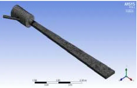
Fig. 2 Three-dimensional modeling using CATIA V5
Fig. 3Cross section of dry ice blasting nozzle geometry
The main properties of dry ice pellets involved in this study are listed in Table 1:
Table 1 – Properties of dry ice pellets
Parameter Values
Temperature / ºC -78.50
Density / Kg/m-3 1560
Heat Capacity / Jkg-1K-1 519.16
2.2
Numerical Simulation Method
Fluent was employed as the computational fluid dynamic solver to predict the gas flow field and discrete particle velocity in the nozzle. The orientation and location of the dry ice particle inlet, which is located on the periphery of the nozzle has limited to the 2-D model. The model simulation is not adequate to reveal all of the aspects of the flow field and particle trajectory. Therefore, a simulation was run using 3-D nozzle model. A volume mesh was created using a hybrid scheme. Hexahedral and tetrahedral elements are generated throughout the domain as shown in Figure 4.
Fig. 4 Mesh generation on the domain using mesh mode Ansys.
Tetrahedral elements are adapted to the regions where the hexahedral scheme is not suitable and will result in a higher skewness. This ensures a higher grid quality and more accurate results. The no-slip condition was used for the nozzle wall because the gas velocity near the wall zone is much low. In this study, the heat transfer process between the gas and the wall was not considered, and thus a fixed heat flux (heat transfer rate) of zero was enforced at the wall. The gas used was ideal, compressible and continuous. A coupled implicit method was used to solve the flow field and the result of that in a steady state was obtained. The standard K–e turbulence model was utilized.
2.3
Verification of Mesh Quality
ANSYS Fluent requires high-quality mesh to avoid numerical diffusion. The mesh quality metrics are involved in order to quantify the quality, however, the skewness and orthogonal are the primary metrics used to evaluate the mesh quality [19]. High meshing quality was represented by the high value of orthogonal quality and lower value of skewness. Skewness of 0.25-0.50 and orthogonal value in the range of 0.70-0.95 are for a very good quality mesh. The value may differ depending on the physicals and the cell location. The range of skewness and orthogonal value based on mesh quality is shown in Figure 5.
Fig. 5 Skewness and orthogonal mesh spectrum [19]
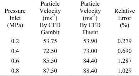
The simulation was performed using Fluent while the reference model taken from previous literature was simulated using CFD meshed with Gambit software. Therefore, model validation of the nozzle geometric is required for this project. The validation was done by comparing the highest maximum particle velocity of the nozzle from the previous literature study as presented in Table 2. The model validation was based on the modeling of dry ice blasting and its application in thermal spray done by Dong et al. [7]. The model was simulated by Ansys Fluent simulation software. An excellent agreement is achieved and confident in the present Fluent solution is, therefore, justifiably high.
Table 2 - Comparing maximum particle velocity using gambit and fluent
Pressure Inlet (MPa)
Particle Velocity (ms-2) By CFD
Gambit
Particle Velocity (ms-2) By CFD
Fluent
Relative Error
(%)
0.2 53.75 53.90 0.279
0.4 72.50 73.00 0.690
0.6 85.50 84.40 1.287
0.8 87.50 88.40 1.029
3.
Results and Discussion
3.1
Nozzle Configuration on Particle Velocity
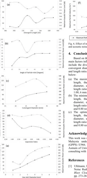
The effect of nozzle configuration dry ice particle velocity is shown in Fig. 6. Dry ice particle velocity and noise emission represent maximum particle velocity and acoustic power level respectively. Dry ice particle velocity increases significantly with the increase in nozzle divergent length [20], especially when the nozzle divergent length is 230 mm as shown in Fig. 6a. This result means that dry ice velocity has an optimum length for the particle acceleration. When the nozzle divergent length > 230 mm. dry ice particle velocity decreases drastically with the further increase in nozzle divergent length. Therefore, dry ice particle velocity is effectively accelerated in a limited length. There has been a study conducted on a modeling of dry ice blasting and found out that the favorable nozzle divergent length is 230 mm. This length gives the highest dry ice particle velocity [7]. Moreover, it is found with great interest from Fig. 6b that the nozzle particle inlet angle increase slightly with increase further increase of nozzle particle inlet angle. This agreement has been supported by the previous study done by Qiang et. al. [15] on CFD research on jet particle inlet angle. It was found that increase particle inlet angle increases the particle jet velocity. Apart from that, Fig. 6c shows that the effect of convergent diameter on particle velocity. It can be seen that increasing convergent diameter increase the particle velocity magnitude. Therefore the selection of nozzle convergent diameter is 35 mm. This diameter gives favorable passage for dry ice blasting particle. It is found with great interest from Fig.
6d that the nozzle expansion ratio has a significant effect on dry ice particle velocity. It is clearly seen that dry ice particle velocity decreases with increasing expansion ratio. Thus the best selection of expansion ratio is 1.0 that give the highest dry ice particle velocity. On the other hand, it is interesting to find out that the gas inlet diameter also plays an important role in particle velocity magnitude. Increasing gas inlet diameter increase the dry ice particle velocity magnitude. This is due to the bigger diameter give sufficient energy coming from the compressed air toward the dry ice blasting particle. Fig. 6f shows the effect of length ratio of compressed air intake section ligs convergent sections lco on dry ice blasting particle velocity. It is clear that the dry ice particle Effect of the divergent section and a convergent section on dry ice particle velocity. Velocity increases remarkably with increasing length ratio.
3.2
Nozzle Configuration on Noise Emission
Fig. 6. Effect of nozzle configuration on dry ice particle velocity and acoustic noise emission
4.
Conclusion
Based on the simulation results, it was found that the main factors influencing significantly the particle velocity include the divergent length, the angle of particle inlet, convergent diameter, expansion ratio, gas inlet diameter and length ratio. The result of the nozzle configuration as below:
(a) The maximum particle velocity for the divergent length, the angle of particle inlet, convergent diameter, expansion ratio, gas inlet diameter and length ratio are 230 mm, 40 mm – 60 mm, 35 mm, 1.00, 6 mm and 0.80 respectively.
(b) The minimum acoustic power level for the divergent length, the angle of particle inlet, convergent diameter, expansion ratio, gas inlet diameter and length ratio are 270 mm, 30 mm, 35 mm, 1.00, 6 mm and 0.80 respectively.
(c) The optimize nozzle configuration for divergent length, the angle of particle inlet, convergent diameter, expansion ratio, gas inlet diameter and length ratio are 230 mm, 30 mm, 35 mm, 1.00, 6 mm and 0.80 respectively.
Acknowledgement
This work was supported by Universiti Tun Hussein Onn Malaysia under Geran Pendidikan Pasca Siswazah (GPPS) /U966. The author acknowledge Dr. Norzelawati Asmuin of Universiti Tun Hussein Onn Malaysia for her consulting with this work.
References
[1] Uhlmann, E., El-Mernissi, A., Andr, and Hollan, R. Noise Reduction of Dry Ice Blasting. Journal of Blast Cleaning Technology. Volume 29, (2008), pp. 273-284.
[2] Spur, G., Uhlmann, E., and Elbing, F. Dry-ice blasting for cleaning: process, optimization and application. International Journal of Wear. Volume 67, (1999), pp. 402–411.
Supersonic Nozzle Flow Simulationsfor Particle Coating Applications: Effects of Shockwaves, Nozzle Geometry, Ambient Pressure and Substrate Location upon Flow Characteristics. Journal of Thermal Spray Technology, Volume 20, (2011) pp. 514-522.
[4] Ramji, V. R., Mukesh, I., and Hasan. Design and Numerical Simulation of Convergent Divergent Nozzle. Journal of Applied Mechanics and Materials. volume 852, (2016), pp. 617–624. [5] Liu, Y. H., Maruyama, H., and Matsusaka, S.
Agglomeration process of dry ice particles . Journal of Advanced Powder Technology, Volume 21, (2010), pp. 652-657.
[6] Liu, Y. H. Analysis of Production Process of Fine Dry Ice Particles and Application for Surface Cleaning. Journal of Advanced Powder Technology, Volume 32, (2012), pp. 23-30.
[7] Dong, S., Song, B., Liao, H., and Coddet, C. Effect of dry-ice blasting on the deposition behavior of molybdenum particles onto aluminum and stainless steel substrates using plasma spraying: From single splat to coating. Journal of Surface. Coatings Technoly, Volume 268, (2015), pp. 46–51.
[8] Munday, D., Gutmark, E., Liu, J., and Kailasanath, K. Flow structure and acoustics of supersonic jets from conical convergent-divergent nozzles. Journal of Physics of Fluid, Volume 24, (2011), pp. 63-67.
[9] Mabe, J. Variable area jet nozzle for noise reduction using shape memory alloy actuators. Journal of Acoustic Paris, Volume 6, (2008), pp. 23-31. [10] Willard, D. C., Mihaloew . J. A., and Callaghan, E.
E. Turbojet Engine Noise Reduction with Mixing Nozzle-Ejector Combinations. Journal of National Aeronautics, Volume 48, (1958), pp. 35-49.
[11] Kuo, Kuo, C. W. Acoustic measurements of models of military style supersonic nozzle jets. Chinese Journal of Aeronautics, Volume 27, (2014), pp. 23– 33.
[12] Sadikin, A., Mohd Bahrin, M. K. A., Ismail, A., Ismail, A. E., Ahmad, S., Salleh, S., Abdol Rahman, M. N., Sapit, A., and Ayop S. S. Numerical Simulation in Transient Flow of Non-Newtonian Fluid in Nozzles during Filling Process.
International Journal of Integrated Engineering, Volume 10, (2018), pp. 92-95.
[13] Kathiresan, K., Balamani, A., Karthik, M., Gogulanathan, P., Thanikaivel Murugan, D., and Ilakkiya, S. CFD Analysis of Supersonic Coaxial Jets on Effect of Spreading Rates. Journal of Engineering Research and Applications, Volume 4, (2014), pp. 29-35.
[14] Abdel-Rahman, A. A Review of Effects of Initial and Boundary Conditions on Turbulent. Journal of Fluid Mechanics, Volume5, (2010), pp. 257-275. [15] Qiang, Z., Wu, M., Miao, X., and Sawhney, R.
CFD research on particle movement and nozzle wear in the abrasive. The International Journal of Advanced Manufacturing Technology, Volume 87, (2018), pp. 86-98.
[16] Callender, B, Gutmark, E., and Martens, S. Far-field acoustic investigation into. Journal of American of Aeronautics and Astronautics, Volume 43, (2005) pp. 87–95.
[17] Tong, X., and Luke, E. Turbulence Models and Heat Transfer in Nozzle Flows. Journal of American of Aeronautics and Astronautics, Volume 65, (2004), pp. 97-103.
[18] Seiner, J., Ukeiley, L., and Jansen, S. Aero performance efficient noise reduction for the F404 400 engine," Journal of American of Aeronautics and Astronautics, Volume 78, (2005),pp. 65-78. [19] Ozen, M. Mesh Metric Spectrum Quality, California.
Journal ofPhysics of Fluid, Volume 48, (2012), pp. 236-267.
![Fig. 1. Active mechanism of dry ice blasting [2]](https://thumb-us.123doks.com/thumbv2/123dok_us/8438246.1700341/1.595.306.537.442.537/fig-active-mechanism-dry-ice-blasting.webp)