INTELLIGENT CONTROL SCHEMES
FOR SSSC BASED DAMPING
CONTROLLERS IN MULTI-MACHINE
POWER SYSTEMS
D. MURALI
Research Scholar in Electrical and Electronics Engineering Department , Government College of Engineering, Bargur-635 104, Tamilnadu, India
Dr. M. RAJARAM
Professor & Head, Department of Electrical and Electronics Engineering , Government College of Engineering, Tirunelveli-627 007, Tamilnadu, India
Abstract :
The main aim of this paper is to damp out power system oscillations, which has been recognized as one of the major concerns in power system operation. This paper describes the damping of power oscillations by hybrid neuro-fuzzy coordinated control of Flexible AC Transmission System (FACTS) based damping controllers. The advantage of this approach is that it can handle the nonlinearities, at the same time it is faster than other conventional controllers. ANFIS (Adaptive Neuro-Fuzzy Inference System) is employed for the training of the proposed fuzzy logic controllers (FLC). Simulation studies are carried out in Matlab/Simulink environment to evaluate the effectiveness of the proposed neuro-fuzzy controller on multi-machine power systems installed with Static synchronous series compensator (SSSC). Results show that the proposed neuro-fuzzy intelligent controls improve the damping performance of the SSSC based damping controllers in the event of a major disturbance.
Keywords: ANFIS, Coordinated control, Damping performance, FACTS, Fuzzy logic, Matlab/Simulink, SSSC, Training of FLC.
1. Introduction
Oscillations of generator angle or line angle are generally associated with transmission system disturbances and can occur due to step changes in load, sudden change of generator output, transmission line switching, and short circuits. Depending on the characteristics of the power system, the oscillations may last for 3-20 seconds after a severe fault. Drawn out oscillations that last for a few seconds or more are usually the result of very light damping in the system and are pronounced at power transfers that approach the line’s stability limit. During such angular oscillation period, significant cycle variations in voltages, currents, and transmission line flows will take place. It is important to damp these oscillations as quickly as possible because they cause mechanical wear in power plants and many power quality problems. The system is also vulnerable if further disturbances occur[1].
The active power oscillations on a transmission line tend to limit the amount of power that may be transferred. This may result in stability concerns or utilization restrictions on the corridors between control areas or utility systems. This is due to the fact that higher power transfers can lead to less damping and thus more severe and possibly unstable oscillations.
Flexible ac transmission system (FACTS) devices are now increasingly used in power systems to improve both the steady state and dynamic performances of the systems[2-6]. The satisfactory damping of power oscillations is an important issue addressed when dealing with the rotor angle stability of power systems. This phenomenon is well known and observable especially when a fault occurs. To improve the damping of oscillations in power systems, supplementary control laws can be applied to existing devices. These supplementary actions are referred to as power oscillation damping (POD) control. In this work, POD control has been applied to Static synchronous series compensator (SSSC).
system is compared for the cases of with and without SSSC based damping controllers in the event of a 3-phase short circuit fault. Simulation results show that in damping power system oscillations , the SSSC with POD control is more effective than the SSSC without POD control.
An attempt has been made to apply hybrid neuro-fuzzy (HNF) approach for the coordination between the conventional power oscillation damping (POD) controllers in a 3-machine power system. With the help of MATLAB, a class of adaptive networks, that are functionally equivalent to fuzzy inference systems, is proposed. The proposed architecture is referred to as ANFIS (Adaptive Neuro-Fuzzy Inference System)[8-10]. The performance of the hybrid neuro-fuzzy controllers is compared with the cases of 3-machine power system (i).with fuzzy coordinated SSSC based damping controllers, (ii).with SSSC, and (iii).without SSSC respectively. Simulation results show that the hybrid neuro-fuzzy coordinated SSSC based damping controllers gives better damping performance as compared to other cases.
2. Power System Model
The single line diagram of a two-machine power system with SSSC is shown in Fig.1. It consists of two power generating stations and a 3-phase load at bus B3. The first power generating station has a rating of 2100 MVA[11] and the other one has a rating of 1400 MVA. The 3-phase load of approximately 2200 MW is modeled using a dynamic load model where the active and reactive power absorbed by the load is a function of the system voltage. The generating substation I is connected to this load by two transmission lines L1 and L2. The line L1 is 280 km long and the line L2 is split into two segments of each 150 km length in order to simulate a three-phase fault (using a fault breaker) at the midpoint of the line. The generating substation II is connected to the load by the line L3 of 100km length. The SSSC is located between the buses B1 and B2. It has a rating of 100 MVA and is capable of injecting upto 10% of the nominal system voltage. This SSSC is a typical three-level PWM converter having a nominal voltage of 40 kV with an equivalent capacitance of 375 μF. On the AC side, its total equivalent impedance is 0.16 p.u. on 100 MVA base. This impedance represents the transformer leakage reactance and the phase reactor of the IGBT bridge of actual SSSC.
Fig. 1 Single line diagram of a two-machine power system with SSSC
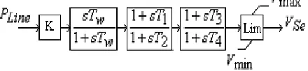
The SSSC injected voltage reference is normally set by a POD (Power oscillation damping) controller. In general, the structure of a FACTS POD controller is shown in Fig.2. It involves a transfer function consisting of an amplification block, a washout block and two lead-lag blocks and an output limiter. Commonly, the local signals of FACTS devices are always applied for the damping control. The inputs to the POD controller are the voltage at bus B2 and the current flowing in the line L1.
Fig. 2The structure of a simple FACTS POD controller
Fig. 3 Single line diagram of a 3-machine power system with two SSSCs
3. Control Scheme
3.1.Conventional FACTS POD Controller
In general, the structure of a series FACTS POD controller is shown in Fig.2. Commonly, the local signals of FACTS devices are always applied for the damping control. In this simulation, the active power (PLine) through
the SSSC is employed. The output is series injection voltage (VSe) which represents the control variable of the
SSSC. The parameters of the POD controller can be adjusted by trial and error[12]. The POD controller parameters are given in Appendix.
3.2.Fuzzy Logic Coordinated Controller Design
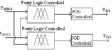
Most of the FACTS POD controllers belong to the PI (Proportional + Integral) type and work effectively in single machine system[12]. However, the performance of the above mentioned POD controllers deteriorates in multi-machine power systems. The damping performance of the POD controllers in multi-machine power systems can be improved by using fuzzy coordinated design[13]. The structure of the proposed fuzzy coordination controller is shown in Fig.4, where the inputs PSSSC1 and PSSSC2 are the active power flows through
SSSCs connected between Bus2 and Bus3, and Bus6 and Bus7 respectively. Thus, the conventional POD controllers are tuned by using fuzzy coordination controllers. The fuzzy coordination controller involves Fuzzification, Inference and Defuzzification units.
Fig. 4 SSSC based fuzzy coordination Controller
3.3.Fuzzification
Fig. 5 Membership Function
3.4.Inference
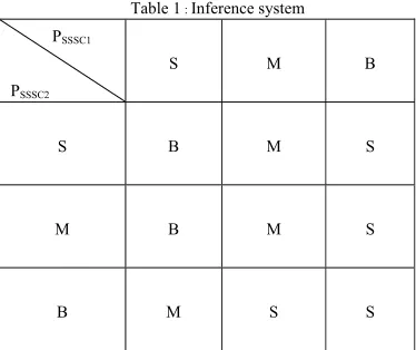
Fuzzy inference system (FIS) involves fuzzy rules for determining output decisions. The fuzzified input variables are mapped onto the output variables using these fuzzy rules. The rules can be obtained from the system operation and the knowledge of the operator. In this paper, the rules are trained using the ANFIS technology. Table 1 shows the inference system.
Table 1 : Inference system PSSSC1
PSSSC2
S M B
S B M S
M B M S
B M S S
3.5.Defuzzification
The defuzzification process transforms the fuzzy results of the inference into a crisp output. In this work, the centroid method is employed.
4. ANFIS Training
In this work, both membership functions and the inference system are optimized using ANFIS technology.
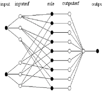
4.1.ANFIS Structure
Commonly, the ANFIS has five layers. In layer 1, each node generates membership grades of a linguistic label. In this paper, as shown in Fig.5, the triangular membership functions are selected. Parameters in this layer are referred to as premise parameters S1 and they can be trained using the ANFIS learning algorithm. Each node in layer 2 is a fixed node and calculates the firing strength of each rule via multiplication of the incoming signals. Nodes in layer 3 compute the normalized firing strength of each rule. In layer 4, there are only adaptive nodes and the output of the ith node is given by :
)
(
p
i
x
q
i
y
r
i
i
i
f
(1)In Eqn.(1),
i
is the output of layer 3.(
p
i
,
q
i
,
r
i
)
are referred to as the consequent parameter set S2. They can also be trained using ANFIS learning algorithms. The single node in layer 5 sums up all the incoming signals :Fig. 6 ANFIS structure
The training procedure is achieved based on the batch learning technique, where the tuning of the fuzzy logic controller is achieved with a back-propagation algorithm using input-output training data set. Considering the computation complexity and the resulting performance, parameters are trained using the gradient descent and the least square estimation (LSE) method.
4.2.Sugeno type Neuro-fuzzy Controller
Adaptive Neuro Fuzzy Inference System (ANFIS)[14-16] is more complex than Fuzzy Inference System (FIS), but users have some limitations : only zero-order or first-order Sugeno fuzzy models, And Method: prod, Or Method: max, Implication Method: prod, Aggregation Method: max, Defuzzification Method: wtaver (weighted average). On the other hand, users can provide to ANFIS their own number of MFs (numMFs) both for inputs and outputs of the fuzzy controller, the number of training and checking data sets (numPts), the MF’s type (mfType), the optimization criterion for reducing the error measure (usually defined by the sum of the squared difference between actual and linearized N curve).
4.3.Membership function Type (mfType)
Gbell MFs are preferred by ANFIS in most cases. For other types of MFs preferred by the user for a certain application (pimf, gaussmf, trimf, gauss2mf, dsigmf and psigmf), there is no rule in choosing them. The general rule is to obtain the best smallest error measure with minimum training parameters. MFs type such as sigmf and zmf are not accepted.
4.4.Number of Membership functions (numMFs)
The great advantage of neuro-fuzzy design method comparing with fuzzy design method consists in the small number of input and output MFs (usually 2…4), which implies the same maximum number of rules. Thus, the rule base and the occupied memory become very small.
4.5.Number of Epochs (numEpochs)
automatically generates a first-order Sugeno fuzzy type, using only 3 triangular MFs and 9 rules. ANFIS automatically trains its fuzzy model 10 epochs. For better results, the number of epochs can be increased.
5. Simulation Results and Discussion
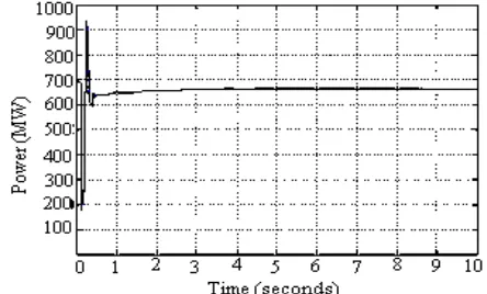
The two-machine power system model shown in Fig.1 is simulated in Matlab/Simulink environment for the cases of both with and without SSSC based damping controllers during a 3-phase short circuit fault of 100 ms duration at bus B4 and the simulation results are shown in Fig.7 and Fig.8. From the simulation results, it is inferred that in damping power system oscillations, the SSSC based damping controller is more effective than the system without damping controllers.
Then the SSSC based damping controller is made use of in the 3-machine power system model shown in Fig.3. A hybrid neuro-fuzzy coordination controller is designed following the procedure presented in the above section. The proposed scheme utilizes Sugeno-type fuzzy inference system controller, with the parameters inside the fuzzy inference system decided by the neural-network back-propagation method.
To verify the performance of the proposed neuro-fuzzy controller, a 3-phase short circuit fault of 100 ms duration is applied at Bus 3 in the 3-machine 9-bus power system model shown in Fig.3. The power system model is simulated in Matlab/Simulink environment for the cases of without SSSCs, with SSSCs, with fuzzy coordinated SSSCs, and with neuro-fuzzy coordinated SSSCs.
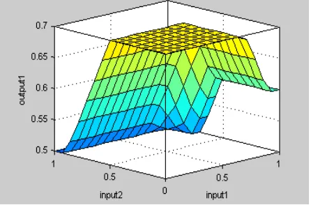
Figs.9-12 show the system dynamic responses for the above mentioned cases. From the Fig.9, it is inferred that a very poor power angle oscillation damping is observed without using SSSC, during a disturbance. From the Figs.10-12, it is clear that the designed neuro-fuzzy controller is robust in its operation and gives a superb damping performance compared with the other three cases. Fig.13 shows the surface plot of the ANFIS model. The input1 is the reference value of VSe. The input2 is the actual value of VSe. The output1 is the reference
value of current from the PI controller. Besides the simple architecture of the neuro-fuzzy controller, it has the potentiality of implementation in real time environment.
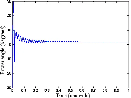
Fig. 7 Damping performance of a two-machine power system without SSSC based damping controller during a 3-phase short circuit fault of 100 ms duration at Bus B4
Fig. 9 Damping performance of 3-machine power system without SSSC during a 3-phase short circuit fault of 100 ms duration at Bus 3
Fig. 10 Damping performance of 3-machine power system with SSSC during a 3-phase short circuit fault of 100 ms duration at Bus 3
Fig. 12 Damping performance of 3-machine power system with Neuro-fuzzy coordinated SSSCs during a 3-phase short circuit fault of 100 ms duration at Bus 3
Fig. 13 Surface plot of proposed ANFIS model
6. Conclusion
In this study, first the simulation of a two-machine power system model with Static synchronous series compensator (SSSC) based damping controllers in the presence of a 3-phase short circuit fault is considered. The results show that the power system oscillations are damped out very quickly with the help of SSSC based damping controllers in few seconds. Next, the simulation of a 3-machine 9-bus power system model with SSSC based damping controllers in the event of a major disturbance is considered. Hybrid Neuro-Fuzzy (HNF) approach is employed for the coordination between the damping controllers for SSSC. The effectiveness of the proposed controller in increasing the damping of oscillations is studied on the 3-machine 9-bus power system model. The simulation results validate the robustness of the proposed control scheme. The results show that the proposed ANFIS technology is having improved dynamic response and at the same time faster than other conventional controllers. Moreover, this approach is also simple and easy to be realized in power systems.
Appendix A.
POD Controller Parameters :
K = 1.82, Tw = 3.0 sec., T1 =T3 = 0.02 sec., T2 =T4 = 0.15 sec.,
Vmax = 0.1, Vmin = -0.1.
References
[1] Y.N. Yu, “Electric Power System Dynamics”, Academic Press, 1983.
[3] Y.I. Abdel-Magid, M.A. Abido, S. AI-Baiyat, and A.H. Mantawy, “Simultaneous Stabilization of Multimachine Power Systems Via Genetic Algorithms”, IEEE Trans. PWRS, Vol.14, No.4, 1999, pp. 1428-1439.
[4] N.G. Hingorani and L. Gyugyi, Understanding FACTS : Concepts and Technology of Flexible AC Transmission Systems, IEEE Press, New York, 2000.
[5] M.A. Abido and Y.L. Abdel-Magid, “Analysis and Design of Power System Stabilizers and FACTS Based Stabilizers Using GA”, Proceedings of PSCC-2002, Session 14 Paper 3, Spain, June 24-28, 2002.
[6] B.S. Righy and R.G. Harley, “An Improved Control Scheme for a Series-capacitive Reactance Compensator Based on a Voltage-Source Inverter”, IEEE Trans. Industry Applications, Vol.34, No.2, 1998, pp.355-363.
[7] W. Qiao and R.G. Harley, “Indirect Adaptive External Neuro-control for a Series Capacitive Reactance Compensator Based on a Voltage Source PWM Converter in Damping Power Oscillations”, IEEE Trans. Industrial Electronics, Vol.54, No.1, 2007, pp. 77-85. [8] J.R. Jang, “ANFIS Adaptive-netwok-Based Fuzzy Inference System”, IEEE Trans. on Systems, Man and Cybernetics, Vol.23, No.3,
1993, pp. 665-685.
[9] S.P. Ghoshal, “Multi-Area Frequency and Tie-Line Power Flow Control with Fuzzy Logic Based Integral Gain Scheduling”, IE (I) Journal-EI, Vol.84, 2003, pp. 135-141.
[10] ”Fuzzy Logic Toolbox”, Available: www.mathworks.com.
[11] L. Angquist, B. Lundin, J. Samuelsson, “Power oscillation damping using controlled reactive power compensation – a comparison between series and shunt approaches”, IEEE Trans. on Power Systems, Vol.8, No.2, 1993, pp. 687-695.
[12] Lijun Cai and Istvan Erlich, “Fuzzy Coordination of FACTS Controllers for Damping Power System Oscillations”, Proc. of Modern Electric Power Systems-2002, miless.uni-duisburg-essen.de.
[13] P.K. Dash, S. Mishra, and G. Panda, “Damping Multi-modal Power System Oscillation Using a Hybrid Fuzzy Controller for Series Connected FACTS Devices”, IEEE Trans. on Power Systems, Vol.15, No.4, 2000, pp. 1360-1366.
[14] Seema Chopra, R. Mitra, and Vijay Kumar, “A Neurofuzzy Learning and its Application to Control System”, International Journal of Computational Intelligence, Vol.3, No.1, 2007, pp. 72-78.
[15] N. Magaji and M.W. Mustafa, “Optimal Thyristor Control Series Capacitor Neuro-Controller for Damping Oscillations”, Journal of Computer Science, Vol.5, No.12, 2009, pp. 983-990.