R E S E A R C H
Open Access
Reduction of rounding noise and lifting
steps in non-separable four-dimensional
quadruple lifting integer wavelet transform
Fairoza Amira Binti Hamzah
1*, Sayaka Minewaki
1, Taichi Yoshida
2and Masahiro Iwahashi
1Abstract
The wavelet transform (WT)-based JPEG 2000 is a standard for the compression of digital images that uses a separable lifting structure in which a multidimensional image signal is transformed separately along its horizontal and vertical dimensions. A non-separable three-dimensional (3D) structure is used to minimize the number of lifting steps in existing methods and can reduce the delay between input and output as each process is implemented by cascading in lifting calculation. This structure reduces rounding noise and the number of steps of the lifting scheme in the transform. The non-separable 3D structure in the 5/3-type transform for lossless coding reduces rounding noise, but it increases in the 9/7-type transform for lossy coding in the structure. A combination of 2D and 3D non-separable structures for 4D integer WT has beenproposedto solve this problem, but the original filter arrangements need to be preserved to reduce rounding noise. Therefore, in this study, a non-separable 2D structure for the integer implementation of a 4D quadruple lifting WT with a 9/7 filter is proposed. The proposed wavelet transform has the same output signal as the conventional separable structure except for the rounding noise. As the order of the original lifting scheme is preserved, rounding noise in pixels of the decoded image can be significantly reduced, and the upper bounds of quality and lossy decoded 4D medical images can be improved.
Keywords:Wavelet, Transform, Lifting, 4D, Rounding, Coding, Quadruple
1 Introduction
Discrete cosine transform (DCT)-based digital image signal compression was superseded by the discrete wave-let transform (DWT)-based JPEG 2000 as the standard used to compress digital images [1]. The JPEG 2000 re-stricts the user’s choice to two wavelet transforms— Dau-bechies 9/7 for lossy compression [2] and the 5/3 LeGall wavelet [3], which has rational coefficients for reversible or lossless compression. The JPEG 2000 also supports arbitrary transform kernels and specifies that they should be implemented by using a lifting scheme [4].
Recent advances in multidimensional image data have en-hanced the importance of research on suitable compression methods. Digital multimedia technologies have progressed from one-dimensional (1D) audio signals, and 2D and 3D image signals to 4D signals. The medical imaging industry
has also progressed to a filmless environment where the amount of digital data that need to be managed presents a significant challenge. Four-dimensional images are increas-ingly being collected and used in clinical and research appli-cations, such as 4D magnetic resonance imaging (MRI), computed tomography (CT), ultrasound, and functional MRI. Four-dimensional medical images have had a signifi-cant influence on the diagnosis of diseases and surgical plan-ning [5]. An image slice resolution of 512 × 512 has been the minimum standard, but nowadays, state-of-the-art scanning systems can output image slices at spatial resolutions of 1024 × 1024 or more at increasing pixel bit depths [6]. Limi-tations on storage space and transmission bandwidth, on the other hand, and the growing size of medical image datasets, on the other, have spurred research on the design of ad hoc tools. The increasing demand for efficiently storing and transmitting digital medical datasets has triggered investiga-tions into multidimensional and dynamic image compres-sion. Thus, a number of studies have examined the compression of 4D medical images, such as [7–9].
* Correspondence:[email protected]
1Department of Electrical, Electronics and Information Engineering, Nagaoka
University of Technology, Niigata, Japan
Full list of author information is available at the end of the article
By adopting the Joint Photographic Experts Group (JPEG) international standard, a class of separable 2D WT has been broadly developed for various applications designed to effi-ciently compress digital still images. As its transfer function is composed of the product of a 1D transfer function in two spatial dimensions, it can inherit the legacy of previously de-signed 1D structures suitable for hardware implementation [10, 11]. It can also feature regularity and low sensitivity to various kinds of noise [12]. Non-separable structures have been primarily introduced to enhance the accuracy of predic-tion by adapting to the local context of neighboring pixels [13,14]. Furthermore, several studies on reducing hardware complexity by introducing parallel processing to image cod-ing were reviewed in [15] and a parallelization of the 2D fast wavelet transform was proposed in [16]. Directionality has recently been utilized in a generalized poly-phase representa-tion [17–19] with the aim of designing adaptive high-pass fil-ters of wavelet transforms.
A new class of non-separable 2D structures has been re-ported in [20–22], where the transfer function can be expressed as a product of four 1D functions. The transform based on this structure is compatible with the separable transform. The non-separable structure is not a cascade of instances of 1D signal processing in a 1D structure, but re-quires multidimensional memory access. This structure can reduce the total number of steps of the lifting scheme and the rounding operations therein.
Various types of wavelet transforms have been reported to analyze the geometry of 4D images [23], 4D hyperspec-tral images [24], 4D medical volumetric data [8,9], 4D light field data [25], and 4D color images [26]. However, most of them use the separable 4D WT that contains a large amount of rounding noise. Therefore, a non-separable 3D integer WT was proposed in [27] to overcome its limita-tions. Unfortunately, this was limited to a double-lifting in-teger WT with a 5/3 filter especially applied for lossless coding. A non-separable quadruple 3D WT with a 9/7 filter was subsequently proposed in [28] for lossy coding. Never-theless, unlike in the double-lifting WT, the variance of rounding noise increased in the quadruple lifting WT even though the number of lifting steps decreased. Rounding noise in the transform can reduce the efficiency of the lossy coding structure. This paper is the first to use a non-separable 4D quadruple lifting integer WT with the aim of reducing rounding noise inside the transform as well as improving its coding performance. Note that a part of this paper was presented in [29].
This paper focuses on lossy coding of 4D signals using the 9/7-type transform based on the quadruple lifting steps, and a reduction in rounding noise in the integer implementation of the transform is affected. As a lifting step needs to wait for the results of calculations from the previous lifting step, many sequential lifting steps incur a long delay between input and output. The real
numbers assumed as signal values inside the transform are rounded into finite-length rational numbers. Shorter lengths imply lower computational load but more rounding noise. The space needed for memory storage can be reduced in a tradeoff with rounding noise [30].
This paper proposes a non-separable 2D quadruple lifting structure for 4D input signals to deal with the problem of degradation in image quality due to integer implementation. It has the advantage that its output sig-nals, apart from rounding noise, are identical to those of a conventional transform the transfer function of which is a product of 16 1D transfer functions. Unlike the prevalent 3D quadruple lifting structure, the order of lifting steps in the original separable 4D transform is preserved. Thus, the total rounding noise is reduced even though the total number of rounding operators re-mains the same as in prevalent methods. Experiments confirmed that the total rounding noise observed in each frequency band of the decoded images was significantly smaller. The upper bounds of the quality-decoded im-ages in lossy coding mode also improved.
The remainder of this paper is organized as follows: Section2introduces the two types of WT and the lifting structure in 1D WT. This structure is extended to the 4D case in Section 3, where the separable 4D structure is presented as “existing I” method. The non-separable structure is introduced in Section3.2. It uses a 3D struc-ture for 4D WT and is referred to as “existing II” method. In Section 4, the proposed methods are intro-duced and compared with the existing methods. They are combinations of non-separable 2D and 3D struc-tures, called the “proposed I method,” and a non-separable 2D structure called“proposed II” method. All methods are experimentally compared in terms of vari-ous aspects of six input signals in Section5. The conclu-sions of this paper are detailed in Section6.
2 Wavelet transform
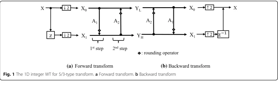
Figure 1 shows the forward and backward transforms of the integer WT developed for the 5/3-type transform of the lossless coding of a discrete 1D signal in JPEG 2000 [31]. Figure1ashows the forward transform of the integer WT and Fig.1bshows its backward transform. It is composed of two lifting steps. The input signal X is down-sampled and fed into the forward transform, which is transformed into a low-frequency band signal,YL, and a high-frequency
band signalYH.A1andA2are the coefficients of the filter
bank, andYLandYHare coded with an entropy encoder to
generate a bit stream for storage and communication. The band signals are then decoded and inversely transformed to obtain the reconstructed signal,X.
9/7-type transform for lossy coding of 4D signals. A problem related to the integer implementation of the transform is addressed here.
In detail, the input signal x(n), n= 0,1, ···, N-1 is di-vided into two groupsx0(m) and x1(m), m= 0,1,···,M-1,
M=N/2. It is expressed with theztransform as
Xcð Þ ¼z ↓2½zcX zð Þ; c∈f0;1g; ð1Þ
for
↓2½X zð Þ ¼ 1 Q
XQ−1
p¼0X z
1 QWp
Q
; WQ¼e j2π
Q; ð2Þ
whereQ= 2 and
X zð Þ ¼XNn¼−01x nð Þz−n; ð3Þ Secondly, the first lifting step is applied as
Xð Þ11ð Þ ¼z X1ð Þ þz R A1½ ð Þz X0ð Þz ; ð4Þ and the second lifting is applied as
Xð Þ02ð Þ ¼z X0ð Þ þz R A2ð Þz X1 ð Þ 1 ð Þz
h i
; ð5Þ
whereA1(z) andA2(z) are filters given as
A1ð Þz A2ð Þz
¼ h1 1þz−1
h21þz−1
; ð6Þ
Finally, the frequency band signals are generated as
YLð Þz
YHð Þz
¼ Xð Þ02 Xð Þ11
" #
; ð7Þ
for
Ybð Þ ¼z
XM−1
m¼0ybð Þm z
−m; b∈fL;Hg; ð8Þ
Note that R[ ] denotes the rounding operator that truncates a pixel value in real numbers to an integer. Calculation in a lifting step starts after the calculation results of the previous have been obtained. The greater the number of lifting steps, the higher the latency (or delay). Therefore, the authors reduce the total numbers of lifting steps and rounding operators in the 4D integer WT in the 9/7-type transform. Note that this paper focuses on reducing rounding noise in the transform to increase the coding performance for 4D data in lossy mode.
In 5/3 type transform, the coefficient values are given as
(a) (b)
Fig. 1The 1D integer WT for 5/3-type transform.aForward transform.bBackward transform
h1 h3 k−1 h2 h4 k
¼ −
1
2 0 1
1
4 0 1
2 6 4
3 7
5; ð9Þ
Lossless reconstruction can be guaranteed with the scaling factors,k−1andkare 1.
The 9/7 type transform has two more lifting steps and scaling. Namely, the third lifting step
Xð Þ13ð Þ ¼z X 1 ð Þ
1 ð Þ þz R A3ð Þz X 2 ð Þ 0 ð Þz
h i
; ð10Þ and the fourth lifting is applied as
Xð Þ04ð Þ ¼z X 2 ð Þ
0 ð Þ þz R A4ð Þz X 3 ð Þ 1 ð Þz
h i
; ð11Þ whereA3(z) andA4(z) are filters given as
A3ð Þz A4ð Þz
¼ h3 1þz−1
h41þz−1
; ð12Þ
In 9/7 type transform, the coefficient values are given as
h1¼−1:586134342059924
h2¼−0:052980118572961
h3¼0:882911075530934
h4¼0:443506852043971
k¼1:230174104914001
; 8 > > > < > > > : ð13Þ
Finally, the frequency band signals are generated with scaling as
YLð Þz
YHð Þz
¼ R k
−12−FXð Þ4 0
h i
R kþ12−FXð Þ3 1
h i
2 4
3
5; ð14Þ
Note that the input signal is scaled with 2Fbeforehand as shown in Fig.2. In the integer implementation,Fis set as a positive number. The smaller theFis, the shorter the bit depth of signals inside the transform will be.
3 Existing methods
3.1 Separable 4D structure (existing I)
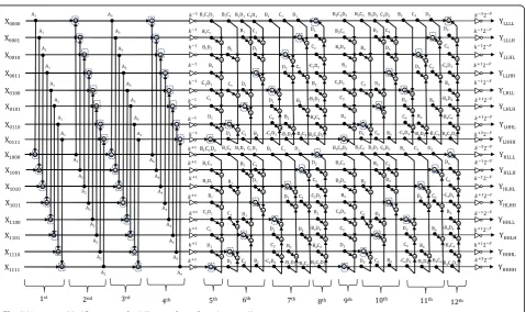
Figure 4 shows the 9/7-type separable 4D integer WT. In the JPEG 2000 standard, the 1D processing shown in Fig.2is applied to a 4D signal along thex,y,z,andt di-mensions, where xand y denote two spatial dimensions within a slice, z denotes the third spatial dimension within a volume, andtdenotes the fourth, temporal, di-mension. However, the separable 4D structure increases the number of rounding operators in the transform. This structure has 192 rounding operators.
For a 4D input signalX(z), the transform splits the input signal into 16 channels, X0000, X0001, X0010, X0011, X0100,
X0101, X0110, X0111, X1000, X1001, X1010, X1011, X1100, X1101,
X1110, and X1111as shown in Fig.3. It is denoted as
X0000ð Þz X0010ð Þz X0100ð Þz X0011ð Þz
⋮
X1110ð Þz X1111ð Þz
2 6 6 6 6 6 6 6 4 3 7 7 7 7 7 7 7 5 ¼
↓2D z1 D
W1ð Þz
↓2D 1
zD
W2ð Þz
⋮
↓2D 1
zD
W8ð Þz
2 6 6 6 6 6 6 6 6 4 3 7 7 7 7 7 7 7 7 5 ; ð15Þ where
W1ð Þz W2ð Þz W3ð Þz W4ð Þz W5ð Þz W6ð Þz W7ð Þz W8ð Þz
2 6 6 6 6 6 6 6 6 6 4 3 7 7 7 7 7 7 7 7 7 5 ¼
↓2C 1
zC
V1ð Þz
↓2C 1
zC
V2ð Þz
↓2C 1
zC
V3ð Þz
↓2C 1
zC
V4ð Þz
2 6 6 6 6 6 6 6 6 6 6 4 3 7 7 7 7 7 7 7 7 7 7 5 ; ð16Þ
V1ð Þz V2ð Þz V3ð Þz V4ð Þz
2 6 4
3 7
5¼ ↓
2B 1
zB P1ð Þz
↓2B 1
zB P2ð Þz
2 6 6 4 3 7 7 5
P1ð Þz P2ð Þz
¼↓2A 1
zA Xð Þz
and
↓2A½Xð Þz
↓2B½Xð Þz
↓2C½Xð Þz
↓2D½Xð Þz
2 6 4 3 7 5¼ 1 Q
XQ−1 p¼0X z
1=Q
A ∙WpQ;zB;zC;zD
1 Q
XQ−1 p¼0X zA;z
1=Q
B ∙WpQ;zC;zD
1 Q
XQ−1
p¼0X zA;zB;z 1=Q C ∙WpQ;zD
1 Q
XQ−1
p¼0X zA;zB;zC;z 1=Q D ∙WpQ
2 6 6 6 6 6 6 6 6 6 4 3 7 7 7 7 7 7 7 7 7 5
∙2F;
ð17Þ
for
Xð Þ ¼z XnN11¼−01XnN22¼−01XnN33¼−01XNn44¼−01
Xð Þnz−n1
A z−Bn2zC−n4z−Dn4;
ð18Þ
wherez= (zA,zB,zC,zD) andn= (n1,n2,n3,n4).
In JPEG 2000 standard, applying the 1st, 2nd, 3rd, and 4th lifting steps in the spatial dimension,xwith
A1ð Þz A3ð Þz A2ð Þz A4ð Þz
¼ h1 1þzþA1
h3 1þzþA1
h2 1þz−A1
h4 1þz−A1
;
ð19Þ
B1ð Þz B3ð Þz B2ð Þz B4ð Þz
¼ h1 1þzþB1
h3 1þzþB1
h2 1þz−1
B
h4 1þz−1
B
;
ð20Þ
and the 9th, 10th, 11th, and 12th lifting steps in the spatial dimension,zwith
C1ð Þz C3ð Þz C2ð Þz C4ð Þz
¼ h1 1þzþC1
h31þzþC1 h2 1þz−C1
h4 1þz−C1
;
ð21Þ
and the 13th, 14th, 15th, and 16th lifting steps in the temporal dimension,twith
D1ð Þz D3ð Þz D2ð Þz D4ð Þz
¼ h1 1þzþD1
h31þzþD1 h2 1þz−D1
h4 1þz−D1
;
ð22Þ
to the channel signals in (7), the transform outputs sixteen frequency band signals YLLLL(z), YLLLH(z),
YLLHL(z), YLLHH(z), YLHLL(z), YLHLH(z), YLHHL(z),
YLHHH(z), YHLLL(z), YHLLH(z), YHLHL(z), YHLHH(z),
YHHLL(z), YHHLH(z), YHHHL(z), and YHHHH(z) as
illus-trated in Fig. 4. This is referred to as a separable structure. As it has a large number of rounding oper-ators, there is a large volume of rounding noise in the transform. A non-separable 3D structure was thus
proposed in [27]. However, when used for a 4D sig-nal, the rounding noise in it significantly increases compared with that in a separable 4D structure. Thus, its coding performance is significantly affected by the rounding noise generated inside it.
3.2 Non-separable 3D structure (existing II)
Figure 5 shows the non-separable 3D structure of inte-ger WT for a 4D input signal designed in the 9/7-type transform based on the structure proposed in [28]. In the first to the fourth lifting steps, the 4D input signal, once it is decomposed into 16 channels, is applied to the spatial dimensionxas in Eq. (19).
Xð Þ0000B ð Þz Xð Þ0001B ð Þz
⋮
Xð Þ1111B ð Þz
2 6 6 4
3 7 7
5¼
R k−1Xð Þ0000A ð Þz
h i
R k−1Xð Þ0001A ð Þz
h i
⋮
R kþ1Xð Þ1111A ð Þz
h i
2 6 6 6 6 6 4
3 7 7 7 7 7
5; ð23Þ
Fig. 4Separable 4D structure for 9/7-type of transform (existing I)
Xð Þ0111D ð Þ ¼z X
B
ð Þ
0111ð Þ þz R k
þ32−FPð ÞD LHHHð Þz
h i
ð24Þ
for
Pð ÞLHHHD ¼
B1ð ÞzC1ð ÞzD1ð Þz B1ð ÞzC1ð Þz B1ð ÞzD1ð Þz
B1ð Þz C1ð ÞzD1ð Þz
C1ð Þz D1ð Þz
2 6 6 6 6 6 6 6 4 3 7 7 7 7 7 7 7 5 T ∙
Xð Þ0000B ð Þz Xð Þ0001B ð Þz Xð Þ0010B ð Þz Xð Þ0011B ð Þz Xð Þ0100B ð Þz Xð Þ0101B ð Þz Xð Þ0110B ð Þz
2 6 6 6 6 6 6 6 6 6 6 4 3 7 7 7 7 7 7 7 7 7 7 5 þ
B3ð ÞzC3ð ÞzD3ð Þz B3ð ÞzC3ð Þz B3ð ÞzD3ð Þz
B3ð Þz C3ð ÞzD3ð Þz
C3ð Þz D3ð Þz
2 6 6 6 6 6 6 6 4 3 7 7 7 7 7 7 7 5 T ∙
Xð Þ0000B ð Þz Xð Þ0001B ð Þz Xð Þ0010B ð Þz Xð Þ0011B ð Þz Xð Þ0100B ð Þz Xð Þ0101B ð Þz Xð Þ0110B ð Þz
2 6 6 6 6 6 6 6 6 6 6 4 3 7 7 7 7 7 7 7 7 7 7 5 ; ð25Þ
in the fifth lifting step. In this step, a 3D filtering with 3D memory accessingB1(z)C1(z)D1(z) is used. In the sixth
lifting step, the calculation ofYLHHL,YLHLH, andYLLHH:
Xð Þ0110D ð Þz Xð Þ0101D ð Þz Xð Þ0011D ð Þz
2 6 4 3 7 5¼
Xð Þ0110B ð Þ þz R k þ1
2−FPð ÞLHHLD ð Þz
h i
Xð Þ0101B ð Þ þz R kþ12−FPD ð Þ
LHLHð Þz
h i
Xð Þ0011B ð Þ þz R k
þ12−FPð ÞD LLHHð Þz
h i 2 6 6 6 4 3 7 7 7 5; ð26Þ for
Pð Þ0LHHLD ð Þz Pð Þ0LHLHD ð Þz Pð Þ0LLHHD ð Þz 2 6 4
3 7
5¼ BB11ð Þð ÞzzCD11ð Þð Þzz B10ð Þz B10ð Þz DC11ð Þð Þzz CD22ð Þð Þzz C1ð ÞzD1ð Þz C1ð Þz D1ð Þz 0 B2ð Þz
2 4
3 5
Xð Þ0000B ð Þz Xð Þ0001B ð Þz Xð Þ0010B ð Þz Xð Þ0100B ð Þz Xð Þ0111B ð Þz
2 6 6 6 6 6 6 4 3 7 7 7 7 7 7 5 ; ð27Þ
Pð Þ00LHHLD ð Þz Pð Þ00LHLHD ð Þz Pð Þ00LLHHD ð Þz 2 6 4
3 7
5¼ BB33ð Þð ÞzzCD33ð Þð Þzz B30ð Þz B30ð Þz DC33ð Þð Þzz CD44ð Þð Þzz C3ð ÞzD3ð Þz C3ð Þz D3ð Þz 0 B4ð Þz
2 4
3 5
Xð Þ0000B ð Þz Xð Þ0001B ð Þz Xð Þ0010B ð Þz Xð Þ0100B ð Þz Xð Þ0111B ð Þz
2 6 6 6 6 6 6 4 3 7 7 7 7 7 7 5 ; ð28Þ
Pð ÞLHHLD ð Þ ¼z P D
ð Þ0
LHHLð Þ þz P D
ð Þ00
LHHLð Þz
Pð ÞLHLHD ð Þ ¼z P D
ð Þ0
LHLHð Þ þz P D
ð Þ00
LHLHð Þz
Pð ÞLLHHD ð Þ ¼z PLLHHð Þ0D ð Þ þz Pð Þ00LLHHD ð Þz
8 > < >
: ; ð29Þ
where R[] denotes the rounding operation on a signal value. Similarly, prediction of X1111, X1110, X1101, X1100,
X1011, X1010, X1001, X1000, X0100, X0010, X0001, and
X0000are also independent. The total numbers of lifting
steps and rounding operators in the non-separable struc-ture were hence reduced from 16 to 12 and 192 to 96, respectively, comparing with the separable structure in Fig. 4. However, the quality of the decoded image was
degraded by the rounding noise inside the transform in its integer implementation. The proposed methods solve this problem as explained below.
4 Proposed methods
4.1 Non-separable 2D and 3D structure (proposed I)
To solve the problems of higher rounding noise and de-graded quality of lossy coding problems, the non-separable structure, which combines both 2D and 3D structures, is proposed. The total number of rounding operators is thus further reduced from 96 to 72. Figure6
illustrates the structure of the proposed I method. Once the 4D input signal is decomposed into 16 channels, the first, second, and third lifting steps are cascaded by using the separable 2D structure, followed by the non-separable 3D structure and the non-separable 1D structure. For example, the first lifting step is expressed as
Xð Þ11c1c21 ð Þ ¼z X11c1c2ð Þz
þR A½ 1B1X00c1c2ð Þ þz A1X01c1c2ð Þ þz B1X10c1c2ð Þz;
wherec1;c2∈f0;1g;
ð30Þ
Even though this proposed method has fewer rounding operators, the rounding noise in it is still higher than in Existing I method, the separable 4D structure. Therefore, it is necessary to maintain the original structure so that rounding noise in the transform is lower.
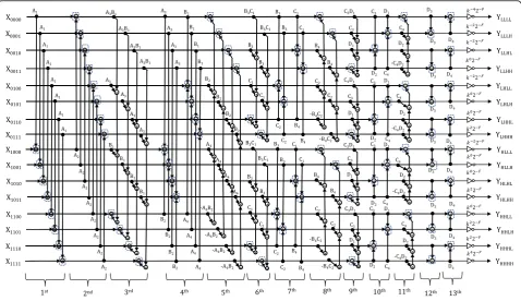
4.2 Non-separable 2D structure (proposed II)
To lower the rounding noise inside the transform, the non-separable 2D structure for 4D input signals is pro-posed. Figure 7 shows the proposed II method. Unlike the existing I, existing II, and proposed I methods, it consists of only a non-separable 2D structure. The ori-ginal order of lifting steps for each dimension is also maintained in this structure. The total number of lifting steps, however, is larger in existing II but smaller than existing I. The total number of rounding operators is smaller in existing I, and the rounding noise is lower, as confirmed in Section5.
The first and second lifting steps involve 1D structures expressed as
Xð Þ11c1c2c3ð Þ ¼z X1c1c2c3ð Þ þz R A½ 1X0c1c2c3ð Þz
Xð Þ01c1c2c3ð Þ ¼z X0c1c2c3ð Þ þz R A½ 2X1c2c3ð Þz
; where c1;c2;c3∈f0;1g
(
;
ð31Þ
Fig. 7Non-separable 2D structure for 9/7-type of transform (proposed II)
Xð Þ11c21c2ð Þ ¼z X 1
ð Þ
11c1c2ð Þz
þR A3B1Xð Þ00c11c2ð Þ þz A3X01cð Þ11c2ð Þ þz B1Xð Þ10c11c2ð Þz
h i
;
wherec1;c2∈f0;1g;
ð32Þ
Thus, proposed II is a combination of non-separable 2D structures and separable 1D structures.
4.3 Comparison of the structures
Table 1 compares the four structures: separable 4D, non-separable 3D, non-non-separable 2D and 3D, and non-non-separable 2D. As summarized in the table, the total number of lifting steps in the proposed non-separable 2D structure increases from 12 to 13 comparing with the existing non-separable 3D structure. However, the total number of rounding operators remains the same. Note that both are still smaller in number than the existing separable 4D structure. A different structure obtained by combining the 2D and 3D structures is first proposed to further reduce the number of rounding operators, but to reduce rounding noise, it is ne-cessary to maintain the original, separable 4D structure. Therefore, the non-separable 2D structure is proposed based on this original structure.
As shown in Fig.4, the existing I method is composed of lifting stepsA1, A2,….,D4, and is expressed as
Separ-able 4D
A1A2A3A4B1B2B3B4C1C2C3C4D1D2D3D4 ð33Þ
In existing I, the order of lifting steps for spatial dimen-sionxremains the same, but those of the steps for dimen-sionsyandz, and temporal dimensiont, change as
Separable 3D’
B1B2C1C2D1D2B3B4C3C4D3D4 ð34Þ
Part of this is implemented in the non-separable 3D structure (existing II).
Non-separable 3D
A1A2A3A4ðB1B2C1C2D1D2Þ3DðB3B4C3C4D3D4Þ3D ð35Þ
Unlike existing II, the proposed I structure is expressed as.
Non-separable 2D & 3D
A1A2B1B2
ð Þ2DðA3A4B3B4C1C2Þ3DðC3C4D1D2Þ2DD3D4 ð36Þ
To maintain the original structure of existing I, pro-posed II is expressed as.
Non-separable 2D
A1A2ðA3A4B1B2Þ2DðB3B4C1C2Þ2DðC3C4D1D2Þ2DD3D4 ð37Þ
Note that the brackets refer to the non-separable structure.
4.4 Derivation of the structure
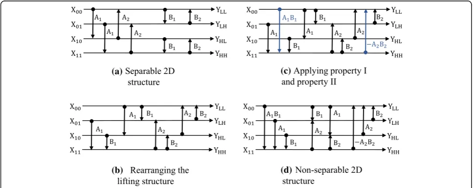
The derivation of the non-separable structure in Figs.5,6, and7from the separable structure in Fig.4is detailed here. We derived it using two the basic properties illustrated in Fig.8and as described in [32]. They are denoted by
PI: Y¼BA∙X¼AC0B∙X; ð38Þ
PII: Y¼AB∙X¼BC1A∙X; ð39Þ
for
A¼ A1 01 00
0 0 1 2 4
3 5;C0¼
1 0 0 0 1 0
þAB 0 1
2 4
3
5;X¼ XX01
X2 2 4
3 5; ð40Þ
B¼ 10 01 00
0 B 1 2 4
3
5;C1¼ 10 01 00 −AB 0 1 2
4
3
5;Y¼ YY01
Y2 2 4
3
5; ð41Þ
By using both the above properties, the process of deriv-ation of the non-separable structure for 4D WT is clarified. The basic properties for modification to be implemented in the non-separable structure shown in Fig.8a, b have differ-ent lifting procedures but are equivaldiffer-ent as shown in Eqs. (38) and (39). By adding properties I and II to the conven-tional separable structure, the lifting can be grouped to-gether, thus reducing the numbers of lifting steps and rounding operations in the transform. Therefore, the non-separable structure can be created systematically to reduce rounding and enhance coding performance.
The process of deriving the non-separable 2D for double lifting is shown in Fig.9based on [32]. Note that the same derivation process is used to obtain the non-separable quadruple 3D structure in Fig. 5, to combine the non-separable 2D and 3D structures for quadruple 4D integer WT as in Fig. 6, and to employ the non-separable 2D structure for quadruple 4D integer WT as in Fig.7.
A clear comparison in terms of the numbers of round-ing operators and liftround-ing steps between the separable and non-separable structures is provided in Fig.10.
Table 1Comparison of the methods
Structure Lifting steps Rounding operators
Memory accessing
Separable 4D (existing I) 16 192 1D
Non-separable 3D (existing II)
12 96 1D and 3D
Non-separable 2D and 3D (proposed I)
12 72 1D, 2D, and 3D
Non-separable 2D (proposed II)
4.5 Lifting steps and latency
The non-separable structure can reduce the numbers of rounding operations and lifting steps in the trans-form. The smaller the number of lifting steps, the lower the overall latency of the transform, as shown in [32]. Figure 11a illustrates an example of the im-plementation of the first lifting step in the double-lifting separable 2D structure shown in Fig. 10a. In this structure, each adder is implemented one by one in a parallel processor with the latency denoted by
“A.” Similarly, denoting the latency of the multipliers by “M,” it takes M+ 2A steps in total. Compared with the non-separable 2D structure in Fig. 10b, four ad-ders are simultaneously implemented in a parallel processor for the first and third lifting steps as shown in Fig. 11b and take M+ 4A steps each. The second lifting step implemented in Fig. 11c is according to Fig. 10b and has M+ 3A steps. As a result, the
separable 2D structure and the non-separable 2D structure took 4M+ 8A and 3M+ 11A steps, respect-ively. Thus, the latency ratio is defined as
L¼3ηþ11
4ηþ8 ; η¼
M
A; ð42Þ
Owing to the number of lifting steps, latency is reduced ifη> 3. Note that the above estimation is valid only for ex-amples shown in Fig.11. As the non-separable 2D and 3D for quadruple 4D integer WT are designed according to the same derivation of non-separable 2D for double 2D in-teger WT, the implementation examples in Fig.11are ap-plicable to them. The proposed non-separable 2D for quadruple 4D integer WT is expected to have lower la-tency than the separable 4D structure.
Fig. 8Basic properties for modification.aProperty I.bProperty II
(a)
(b)
(c)
(d)
5 Experimental results and discussions
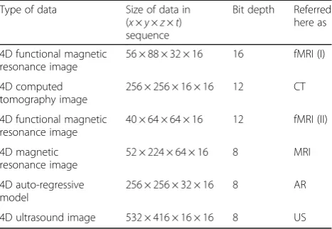
In the following experiments, six types of data were used to evaluate the rounding noise and coding performance, as shown in Table2.
Note that the MRI, functional magnetic resonance image (fMRI)(II), and US data were retrieved from [33,
34] and [35], respectively. MRI data represent highly
correlated data at consecutive time points with limited motion in the temporal dimension t and structural changes in the spatial dimensionz.
Each image is normalized to the range [0, 255] for display purposes as shown in Fig.12a–f. In this paper, the variance in noise in frequency domain and coding performance in lossless and lossy coding modes were investigated.
(a)
(b)
Fig. 10Separable and non-separable 2D structures.aSeparable 2D structure for double lifting with eight rounding operators and four lifting steps.bNon-separable 2D structure for double lifting with four rounding operators and three lifting steps
(a) (b) (c)
The 4D auto-regressive (AR) model used in our exper-iments can be expressed as
xð Þ1 n
1;n2;n3;n4
ð Þ ¼x nð 1;n2;n3;n4Þ þρ∙xð Þ1ðn1−1;n2;n3;n4Þ xð Þ2 n
1;n2;n3;n4 ð Þ ¼xð Þ1 n
1;n2;n3;n4
ð Þ þρ∙xð Þ2 n
1;n2−1;n3;n4
ð Þ
xð Þ3ðn1;n2;n3;n4Þ ¼xð Þ2ðn1;n2;n3;n4Þ þρ∙xð Þ3ðn1;n2;n3−1;n4Þ xð Þ4ðn1;n2;n3;n4Þ ¼xð Þ3ðn1;n2;n3;n4Þ þρ∙xð Þ4ðn1;n2;n3;n4−1Þ
8 > > < > >
: ;
ð43Þ
Note that ρ was set to 0.9 in the experiments in this paper, as the typical values of ρ for natural images are between 0.9 and 0.98 [36].
5.1 Evaluation of rounding noise
As fewer rounding operators do not imply fewer round-ing errors in total [21, 22], the total rounding noise in
the output frequency band signal was investigated. The rounding operation is a vital part of lossy compression.
A non-linear operation transforms a floating-point sig-nal into an integer sigsig-nal. An equivalent expression to the rounding operation is shown in Fig.13. A non-linear equation with additive noise is defined as
SRo ¼SRið Þ þz NRð Þz ; ð44Þ where SRi, SRo, andNRdenote the input signal, the out-put signal, and the additive noise of the rounding oper-ation, respectively. As the correlation between each of the of the errors and the signals was zero (based on stat-istical independence), the variance of output signal was calculated from
σ2
SRo ¼σ2SRi þσ
2
NR; ð45Þ
whereσ2
SRi, σ
2
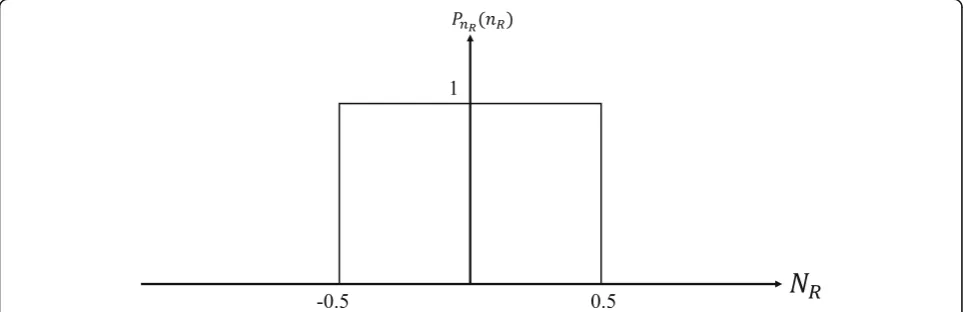
SRo, andσ2NR refer to the variance of the in-put signal, the outin-put signal, and the additive noise of the rounding operators, respectively. As the power of the probability density function (PDF) of additive noise is approximately flat, as shown in Fig.14, the variance of the additive noise for the rounding operations was calcu-lated as
σ2
NR ¼ Z 0:5
−0:5x 2
dx¼ 1
12; ð46Þ
In this study, rounding noise inside the circuit was mea-sured to observe the accumulative error in it due to the rounding operators. Figure 15 illustrates that rounding
Table 2Type of data used in the experiments
Type of data Size of data in (x×y×z×t) sequence
Bit depth Referred here as
4D functional magnetic resonance image
56 × 88 × 32 × 16 16 fMRI (I)
4D computed tomography image
256 × 256 × 16 × 16 12 CT
4D functional magnetic resonance image
40 × 64 × 64 × 16 12 fMRI (II)
4D magnetic resonance image
52 × 224 × 64 × 16 8 MRI
4D auto-regressive model
256 × 256 × 32 × 16 8 AR
4D ultrasound image 532 × 416 × 16 × 16 8 US
(a)
(b)
(c)
(d)
(e) (f)
noise was examined by using the error between the inte-ger signal and the real number signal. Rounding noise is defined by Eq. (47).
error¼y−yb; ð47Þ
Rounding noise was evaluated in six types of input sig-nals to compare the conventional and the proposed lift-ing structures, as shown in Fig.16a–f.
Figure 16a–f indicate the variance of the rounding error in each frequency band for fMRI(I), CT, fMRI(II), MRI, AR, and US data respectively. The average magni-tude of rounding errors for all data was reduced to 19. 11, 16.08, 16.81, 5.63, and 16.09%, respectively, except for US data, which was increased by 15.47%, between existing I structure and proposed II structure, as shown in Fig. 17. However, as the rounding noise in the LLLL frequency band for proposed II structure for the US data was lower than that in existing I, the coding perform-ance on the US data for proposed II method improved as shown in Fig. 20f. The HHHH frequency band of the existing II structure was the highest and resulted in a degradation in coding performance. The energy of the frequency band should be compacted to a low-frequency band signal to reduce entropy in the compressed image and enhanced coding performance. The higher the
variance of rounding noise in the low-frequency band signal, the lower the entropy of the compressed image. However, all structures had the highest compacted en-ergy in the high-frequency band signals. Therefore, we conclude that the lowest variance in rounding noise among all frequency band signals yields the best coding performance.
The reason for why the total number of rounding operators did not influence total rounding noise is in-vestigated in Fig. 18, which shows the variance of rounding noise in the frequency domain. In an ex-periment, only one rounding operator in the forward transform was activated. The horizontal axis denotes the activated rounding operator, numbered from top to bottom, from left to right in Figs. 4 to 7. As sum-marized in Table 1, the existing I, existing II, pro-posed I, and propro-posed II structures had 192, 96, 72, and 96 rounding operations, respectively. The total rounding noise in proposed II decreased even though the number of rounding operations, the source of the noise, remained the same as that in the existing II structure. This is because of the relatively large vari-ance in error in the structure. The varivari-ance in round-ing noise was the highest in the 63rd roundround-ing operator at 0.1844, the ninth rounding operator at 1. 2217, the 14th rounding operator at 0.5964, and the 56th rounding operator at 0.2127 for existing I,
Fig. 13Rounding operation and its equivalent expression
Fig. 15Rounding noise between integer and real number
(a)
(c)
(b)
(d)
(f)
(e)
existing II, proposed I, and proposed II, respectively. However, the average rounding noise in proposed II relative to existing I decreased by almost half from 0. 0646 to 0.0382. It can be concluded that the more frequent and the greater the extent to which noise is amplified in the lifting structure, the higher the rounding noise inside it. As the rounding noise inside the transform influences coding performance, it is in-vestigated in Section 5.2.
5.2 Evaluation of coding performance
Figure 19 illustrates the rate distortion curve, which compares the performance of the methods in the lossy coding mode for CT images. The horizontal and vertical axes represent the entropy rate measured in bits per pixel (bpp) and the peak signal-to-noise ratio (PSNR) of
the reconstructed signal, respectively. It shows that the proposed II structure outperformed the others at the same bitrate. The quality of the reconstructed signal in proposed II increased by 0.18, 16.11, and 26.44 dB over existing I, existing II, and proposed I, respectively. As the quality of the reconstructed image deteriorated con-siderably if it was transformed using existing II and pro-posed I. Figure 20a–e shows the coding performance results when images were transformed using existing I and proposed II only.
Figure20a–eshows the coding performance of existing I and proposed II on fMRI(I), fMRI(II), MRI, AR, and US data, respectively. Under the same bitrate, the quality of the reconstructed signal for proposed II increased by 0.40, 2.10, 0.27, 2.57, and 0.72 dB for fMRI(I), fMRI(II), MRI, AR, and US data, respectively. As both quantization noise
Fig. 17Average variance of rounding noise in each frequency band
and rounding noise were present in the lossy compression system, even though the former for all structures was the same, rounding noise in the proposed II structure was the lowest. Thus, the coding performance of this structure was the best. In conclusion, proposed II structure outper-formed all other structures in the experiments.
6 Conclusions
This paper proposed a non-separable 2D structure for 4D input signals in lieu of non-separable 3D structures. The total number of rounding operators was reduced by half compared with the prevalent separable 4D structure. How-ever, rounding noise owing to the integer implementation
of signal values inside the transform increased in the non-separable 3D structure, due to a change in its original lifting scheme. Therefore, by maintaining the original scheme, the proposed non-separable 2D structure reduced total round-ing noise in it and enhanced the quality of the recon-structed signal in lossy coding. Furthermore, the number of lifting steps, a reduction in which reduces the latency of the overall transform, was also reduced by 18.75% between the proposed non-separable 2D structure and the conventional separable 4D structure on the quadruple 4D integer WT. Our integer WT has the advantage of compatibility with the conventional integer WT. It also enhances compression performance on 4D images, such as medical images.
Fig. 19Coding performance in lossy mode for CT image
(a) (b) (c)
(d) (e)
Abbreviations
1D:One-dimensional; 2D: Two-dimensional; 3D: Three-dimensional; 4D: Four-dimensional; AR: Auto-regressive; Bpp: Bits per pixel; CT: Computed Tomography; DCT: Discrete cosine transform; DWT: Discrete wavelet transform; fMRI: Functional magnetic resonance image; JPEG: Joint photographic experts group; MRI: Magnetic resonance imaging; PDF: Probability density function; PSNR: Peak signal-to-noise ratio; US: Ultrasound; WT: Wavelet transform
Acknowledgements
We thank Saad Anis, Ph.D,, from the Edanz Group (www.edanzediting.com/ac) for editing a draft of this manuscript.
About the authors
Fairoza Amira Binti Hamzah received the Diploma of Electrical and Electronics Engineering from the Japanese Associate Degree Program, Selangor Industrial University, Malaysia, in 2012. Then, she received B. Eng. and M. Engrg. degree in Electrical, Electronics and Information Engineering in Nagaoka University of Technology in 2014 and 2016, respectively, and is currently pursuing Ph.D. of Engineering in the Information Science and Control Engineering department of the same university. In 2017, she had a research internship experience in Department of Computer Science, University of Warwick, UK. Her research interests are in digital signal processing and image compression. She is a Graduate Member of Board of Engineers Malaysia (BEM) and the Institute of Engineers Malaysia (IEM), and a Graduate Student Member of IEEE.
Sayaka Minewaki received her B. Eng. and M. Eng. degrees in Engineering from Kyushu Institute of Technology in 2001 and 2003, respectively. In 2006, she finished a Ph.D. program without dissertation at the Department of Artificial Intelligence, Kyushu Institute of Technology. In 2006, she joined the Yuge National College of Technology, where she served concurrently as a Lecturer. In 2016, she joined Nagaoka University of Technology, where she is currently an Assistant Professor of the Department of Electrical, Electronics and Information Engineering. Her research interests are in the fields of digital signal processing, image compression and natural language processing. Taichi Yoshida received B. Eng., M.Eng., and Ph.D. degrees in Engineering from Keio University, Yokohama, Japan, in 2006, 2008, and 2013, respectively. In 2014, he joined Nagaoka University of Technology as an Assistant Professor in the Department of Electrical, Electronics and Information Engineering. He then joined the University of Electro-Communications, Tokyo, Japan in 2018. His research interests are in the field of filter bank design and image coding application. He is a member of IEEE. Masahiro Iwahashi received his B. Eng, M. Eng., and D. Eng. degrees in electrical engineering from Tokyo Metropolitan University in 1988, 1990, and 1996, respectively. In 1990, he joined Nippon Steel Co. Ltd. From 1991 to 1992, he was dispatched to Graphics Communication Technology Co. Ltd. In 1993, he joined Nagaoka University of Technology, where he is currently a professor of the Department of Electrical Engineering, Faculty of Technology. From 1995 to 2001, he served concurrently as a lecturer of Nagaoka Technical College. From 1998 to 1999, he was dispatched to Thammasat University in Bangkok, Thailand, as a JICA expert.
His research interests are in the area of digital signal processing, multi-rate systems, and image compression. From 2007 to 2011, he served as an editorial committee member of the transaction on fundamentals. He is serving as a reviewer of IEEE, IEICE, and APSIPA. He is currently a senior member of the IEEE and IEICE.
Availability of data and materials Please contact author for data requests.
Authors’contributions
The corresponding and first author is the person who made the substantial contributions to the conception and design, acquisition, analysis and interpretation of the data. The manuscript is critically revised for intellectual content by the second, third, and fourth authors.
Ethics approval and consent to participate Not applicable.
Competing interests
The authors declare that they have no competing interests.
Publisher’s Note
Springer Nature remains neutral with regard to jurisdictional claims in published maps and institutional affiliations.
Author details
1Department of Electrical, Electronics and Information Engineering, Nagaoka
University of Technology, Niigata, Japan.2Department of Computer and
Network Engineering, The University of Electro-Communications, Tokyo, Japan.
Received: 13 July 2017 Accepted: 24 April 2018
References
1. M Unser, T Blu, Mathematical properties of the JPEG 2000 wavelet filters. IEEE Trans. Image Process.12(9), 1080–1090 (2003)
2. M Antonini, M Barlaud, P Mathieu, I Daubechies, Image coding using wavelet transforms. IEEE Trans. Image Process.1(2), 205–220 (1992) 3. D Le Gall, A Tabatai, inInternational Conference on Acoustics, Speech and
Signal Processing. Subband coding of digital images by using symmetric short kernel filters and arithmetic coding techniques (1988)
4. W Sweldens, The lifting scheme: a custom design construction of biorthogonal wavelets. Appl. Comput. Harmon. Analysis3(2), 186–200 (1996)
5. A Nait-Ali, C Cavaro-Menard,Compression of Biomedical Images and Signals
(Wiley, USA, 2008)
6. HK Huang,PACS and Imaging Informatics: Basic Principles and Applications
(Wiley, USA, 2010)
7. R Rajeswari, R Rajesh, inWorld Congress on Nature & Biologically Inspired Computing. Efficient compression of 4D fMRI images using Bandelet transform and fuzzy thresholding (IEEE, India, 2009).
8. V Sanchez, P Nasiopoulos, R Abughrabieh, Novel lossless fMRI image compression based on motion compensation and customized entropy coding. IEEE Trans. Inf Techno Biomed13(4), 645–655 (2009)
9. HG Lalgudi, A Bilgin, MW Marcellin, A Tabesh, MS Nadar, TP Trouard, Four-dimensional compression of fMRI using JPEG 2000. Proc. of SPIE, Medical Imaging: Image Processing5747, 1028–1037 (2005)
10. C Chrysafis, A Ortega, Line-based, reduced memory, wavelet image compression. IEEE Trans. Image Process.9(3), 378–389 (2000)
11. G Shi, W Liu, L Zhang, F Li, An efficient folded architecture for lifting-based discrete wavelet transform. IEEE Trans. Circuits, Systems II express briefs
56(4), 290–294 (2009)
12. M Vetterli, C Herley, Wavelets and filter banks: theory and design. IEEE Trans. Signal Processing40(9), 2207–2232 (1992)
13. DS Taubman, inIEEE International Conference on Image Processing. Adaptive, non-separable lifting transforms for image compression (1999)
14. S Fukuma, M Iwahashi, N Kambayashi, inIEEE International Symposium on Circuits and Systems. Adaptive multi-channel prediction for lossless scalable coding (1999)
15. C Yan, Y Zhang, J Xu, F Dai, L Li, Q Dai, F Wu, A highly parallel framework for HEVC coding unit partitioning tree decision on many-core processors. IEEE Signal Process Lett21(5), 573–576 (2014)
16. J Franco, G Bernabe, J Fernandez, ME Acacio, inEuromicro Int. Conf. On Parallel, Distributed and Network-Based Processing. A parallel implementation of the 2D wavelet transform using CUDA (IEEE, Germany, 2009)
17. T Yoshida, T Suzuki, S Kiyochi, M Ikehara, Two dimensional non-separable adaptive directional lifting structure of discrete wavelet transform. IEICE Trans. FundamE94-A(10), 1920–1927 (2011)
18. T Bruylants, A Munteanu, P Schelkens, Wavelet based volumetric medical image compression. Signal Process. Image Commun.31, 112–133 (2015) 19. FA Binti Hamzah, T Yoshida, M Iwahashi, H Kiya, Adaptive directional lifting
structure of three dimensional non-separable discrete wavelet transform for high resolution volumetric data compression. IEICE Trans. FundamE99-A(5), 892–899 (2016)
20. M Iwahashi, H Kiya, inIEEE International Conference Image Processing. Non separable 2D factorization of separable 2D DWT for lossless image coding (2009) 21. T Strutz, I Rennert, Two-dimensional integer wavelet transform with
reduced influence of rounding operations. EURASIP J Advances Signal Process75(2012).https://doi.org/10.1186/1687-6180-2012-75
(InTechOpen, 2013). Available from:https://www.intechopen.com/books/ discrete-wavelet-transforms-a-compendium-of-new-approaches-and-recent- applications/non-separable-two-dimensional-discrete-wavelet-transform-for-image-signals
23. Y Wang, H Hamza, inIndustrial Engineering Research Conference. 4D geometry compression based on lifting wavelet transform (The Institute for Operations Research and the Management Sciences, Florida, 2006) 24. JM Gomez, JB Rapesta, I Blanes, LJ Rodriguez, FA Llinas, JS Sagrista,“4D
remote sensing image coding with JPEG2000,”Satellite Data Compression, Communications and Processing VI,vol. 7810, 2010.https://doi.org/10.1117/ 12.860545
25. C-L Kuo, Y-Y Lin, Y-C Lu, inIEEE Int. SOC Conference. Analysis and implementation of discrete wavelet transform for compressing four-dimensional light field data (IEEE, Germany, 2013)
26. A Sang, T Sun, H Chen, H Feng, inInt. Conf. On Image Analysis and Signal Processing. A 4D nth-order Walsh orthogonal transform algorithm used for color image coding (IEEE, China, 2010)
27. M Iwahashi, T Orachon, H Kiya, inIEEE International Conference on Image Processing. Three dimensional discrete wavelet transform with deduced number of lifting steps (2013)
28. M Iwahashi, T Orachon, H Kiya, inProc. of Asia Pacific Signal and Information Processing (APSIPA) Annual Summit and Conference (ASC). Non separable 3D lifting structure compatible with separable quadruple lifting DWT (2013) 29. FA Binti Hamzah, T Yoshida, M Iwahashi, inProc. of IEEE ICASSP.
Non-separable Quaruple lifting structure for four-dimensional integer wavelet transform with reduced rounding noise (IEEE, New Orleans, 2017) 30. M Iwahashi, H Kiya, inDiscrete Wavelet Transforms. Condition on word
length of signals and coefficients for DC lossless property (InTechOpen, ISBN 978-953-307-313-2, 2011), pp. 231–254. Available from:https://www. intechopen.com/books/discrete-wavelet-transforms-algorithms-and- applications/condition-on-word-length-of-signals-and-coefficients-for-dc-lossless-property-of-dwt
31. “Joint Photographic Experts Group: JPEG 2000 Image Coding System”. Patent ISO / IEC FCD 15444-1, 2000.
32. S Poomrittigul, M Iwahashi, H Kiya, Reduction of lifting steps of non separable 2D quadruple lifting DWT compatible with separable 2D DWT. IEICE Trans. Fundam. Electron. Commun. Comput. Sci.E97-A(7), 1492–1499 (2014) 33. D Boye et al., inProc. SPIE 8669, Medical Imaging 2013: Image Processing.
Population based modeling of respiratory lung motion and prediction from partial information (2013)
34. JV Haxby, MI Gobbini, ML Furey, A Ishai, JL Schouten, P Pietrini, Distributed and overlapping representations of faces and objects in ventral temporal cortex. Science293(5539), 2425–2430 (2001)
35. C Cortes, L Kabongo, I Macia, OE Ruiz, J Florez,Ultrasound image dataset for image analysis algorithms evaluation,Innovation in Medicine and Healthcare 2015. Smart Innovation, Systems and Technologies, vol 45 (2015), pp. 447–457 36. J-R Ohm, inMultimedia communication technology: representation,

![Fig. 8 and as described in [32]. They are denoted by](https://thumb-us.123doks.com/thumbv2/123dok_us/885921.1586020/9.595.314.540.311.471/fig-described-denoted.webp)