28
Real And Reactive Power Saving In Three Phase
Induction Machine Using Star-Delta Switching
Schemes
Ramesh Daravath, Lakshmaiah Katha, Ch. Manoj Kumar, AVS Aditya
ABSTRACT: Induction machines are the most commonly used industrial drives for variety of applications. It has been estimated that induction motors consumes approximately 50 % of all the electric energy generated. Further, in the area of renewable energy sources, such as wind or bio-mass energy, induction machines have been found suitable for functioning as generators. In this context, it may be mentioned that a star-delta switching is common for the starting of three-phase induction motor. Now, it is proposed to use this star-delta switching for energy conservation of induction machines, i.e., at times of reduced loads, the machine switched back to star connection. Using a three-phase, 400 V, 50 Hz, 4-pole induction machine, it has been demonstrated that the star-delta switching of stator winding of three-phase induction machine (motor / generator operations) reconnected in star at suitable reduced loads with a switching arrangement, can result in improved efficiency and power factor, as compared to a fixed delta or star connection. The predetermined values along with the experimental results have also been presented in this report. A simulation program has been developed for the predetermination of performance of the phase induction machine using exact equivalent circuit. A case study on a 250 kW, 400 V, 4-pole, three-phase induction machine, operated with different load cycles, reveals the significant real and reactive power savings that could be obtained in the present proposal.
Index Terms: Real and Reactive power saving, light loading, case study of induction machine, phase controlled anti parallel thyristor bank, star-delta switching, harmonics, predetermined values
————————————————————
1
I
NTRODUCTIONIn recent years, there is an increased emphasis on the energy saving in electrical apparatus and systems. Since Induction motors form major portion of electrical load in industries, reactive power/energy saving in induction machines can be principally achieved by minimising iron loss in the motors at a light load by means of decreasing the voltage impressed to the stator terminals [1-3]. A phase control circuit using anti-parallel thyristor units can be designed as a closed loop scheme for automatically adjusting the stator terminal voltage of induction motor depending on the load conditions. It is also known that the simple star-delta switch commonly used for starting delta connected induction motors can also be employed for running the motor in star connection during the periods of reduced loads. The maximum load for star connection can be about 40 % of the rated load, the applied voltage being reduced by 1/3 times of normal value. In this paper it is proposed that this star-delta configuration can be more profitably used for improving the power factor and efficiency of operation of the motor/ generator at reduced load conditions.
EXACT EQUIVALENT CIRCUIT OF THREE-PHASE INDUCTION MACHINE
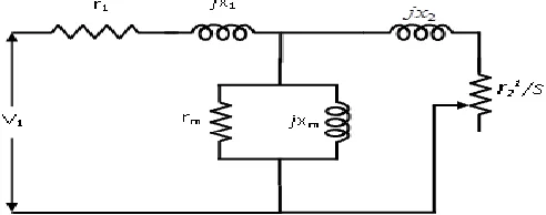
Exact equivalent circuit shown in fig.1 determines the total performance of induction machine and the expression for the various performance quantities are calculated as per the following equations [5]:
Fig. 1 Equivalent circuit of induction machine
Stator impedance Z1=r1+jx1
E1=V1*Z12S/( Z1+ C1* Z12S)
Where C1=1+Z1Ym
I21=E1/Z12S, Z12S=(r21/s) +jx21
Rotor input=I21r21/s
Rotor losses = I21r2
Rotor output Pm= I21r21/s -losses
Torque= V12* r21/s /[(r1+ r21/s)2+(x+C1x21)2]
I1=I21 (1+YmZ2S1)
Stator input P1 = V1I1cos1 (2.9)
Efficiency (η) =Pm/P1*100 (2.10)
STAR- DELTA SWITCHING
Applications requiring varying loads, a two-stage star-delta operation would result in improved overall efficiency and power factor compared to a fixed stator connection. For this two-stage operation, it requires six terminals to be taken out to the machine terminal box. Based on the load variation on the machine, the stator winding has to be switched from one setting to the other. Such a controller can be built as a solid state configuration, using 5 pairs of anti-parallel thyristor units as shown in Fig. 2, suitable for the proposed two-stage switching. Appropriate thyristor units should be given gate pulse and switched-on to obtain the required stator connections. The thyristor units to be switched-on and the corresponding stator connections are given in Table 1. Starting with the delta-connected stator at full load, star-connection will be used during suitable reduced loads. Thus, with the same sinusoidal applied line voltage (VL) to the motor terminals, the voltage per section for each of the settings are as follows:
Stator connection Voltage per section
(i) Delta () VL
(ii) Star (Y)
V
/
3
L Table 1
29 Fig. 2 Star-delta switching circuit (two-stage operation)
The delta / star settings of stator winding connections and the corresponding thyristor units to be switched-on
Table 1
CALCULATIONS OF SAVINGS FOR MOTORING OPERATION
A three-phase, 4-pole, 400 V, 250 kW induction motor with a delta / star stator winding is considered. Typical resistance and reactance parameters (all in terms of stator) for this machine are R1 = 0.033 Ω, R2 = 0.025 Ω, X1 = 0.150 Ω, X2 = 0.150 Ω, Rm = 40.0 Ω and Xm = 5.250 Ω. For the calculation of kWh and kVARh taken by the motor, the loading pattern of the motor over the day is to be known and it depends on the application of the motor. For the present study, two loading patterns given in Table. 2 are considered.
Loading Numbers of hours in a day at each loading Pattern 1 Pattern 2
Full load 3 2
(3/4) Full load 3 2
(1/2) Full load 3 1
(1/3) Full load 3 1
(1/4) Full load 3 5
(1/5) Full load 3 5
(1/10) Full load 3 5
No load 3 3
Table. 2 Loading patterns considered for the motor over a day
To prove the benefit of using the two-stage switching, with each of the loading pattern given in Table 2, the kWh and kVARh taken by the motor in a day are calculated for the following cases:
i. motor operated with the two-stage star- delta switching i.e. with delta connection in the range of 250 kW to 140 kW and in the star connection in the range of 140 kW to no-load
ii. No switching (i.e., motor operated only in delta connection at all loads)
For any given load on the motor, the real power (kW) and reactive power (kVAR) input to the motor can be calculated. Then, kWh and kVARh can be calculated taking into account, the time duration at each load setting. As an example, such calculations made with loading pattern 1, are given in Table. 3. Table. Table 3 Daily kWh and kVARh taken by the 250 kW case study motor for loading pattern 1 for two-stage stator switching(stator winding connection for each load is also indicated)
Table 3
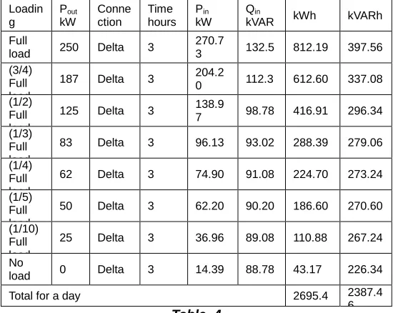
Let the motor be operated with a fixed stator connection from full load to no-load namely, delta connection itself. The kWh and kVARh calculations made with loading pattern 1 are given in Table. 4. Table. 4 Daily kWh and kVARh taken by the 250 kW case study motor for loading pattern 1 with fixed delta stator winding connection
Loadin g Pout kW Conne ction Time hours Pin kW Qin
kVAR kWh kVARh
Full
load 250 Delta 3
270.7
3 132.5 812.19 397.56 (3/4)
Full load
187 Delta 3 204.2
0 112.3 612.60 337.08 (1/2)
Full load
125 Delta 3 138.97 98.78 416.91 296.34
(1/3) Full load
83 Delta 3 96.13 93.02 288.39 279.06
(1/4) Full load
62 Delta 3 74.90 91.08 224.70 273.24
(1/5) Full load
50 Delta 3 62.20 90.20 186.60 270.60
(1/10) Full load
25 Delta 3 36.96 89.08 110.88 267.24
No
load 0 Delta 3 14.39 88.78 43.17 226.34
Total for a day 2695.4 2387.4
6 Table. 4
Stator winding connection Thyristor units to be given gate pulse
Delta D1, D2, D3, E1, E2 & E3 Star S1, S2, S3, T1, T2 & T2
Loadin g Pou t kW Conn ection Time Hours Pin kW Qin
kVAR kWh kVARh
Full load
25
0 Delta 3
270.7 3
132.5 2
812.
19 397.56 (3/4)
Full load
18
7 Delta 3
204.2 0
112.3 6
612.
60 337.08
(1/2) Full load
12
5 Star 3
136.2
0 65.77 408.
60 197.31
(1/3) Full load
83 Star 3 90.24 44.17 270.
72 132.51
(1/4) Full load
63 Star 3 68.07 37.45 204.
21 112.35
(1/5) Full load
50 Star 3 54.97 34.49 164.
91 103.47
(1/10) Full load
25 Star 3 29.21 30.72 87.6
3 92.16
No
load 0 Star 3 6.46 29.6 19.3 8 88.8
Total for a day 2580
.24
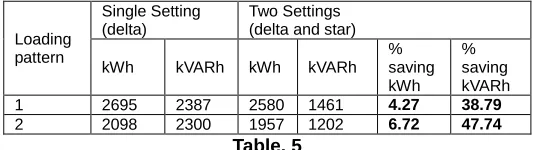
30 For each of the above two cases, similar calculations were
made for the other loading pattern listed earlier in Table. 2. The summary of kWh and kVARh values is given in Table. 5 . Taking the single setting as the reference, the percentage saving in kWh and kVARh in the two-stage switching is also shown in the Table 5. It can be concluded that, compared to the fixed stator connection, the two-stage operation gives an increased saving in kWh and kVARh. Consequently, in industries employing a number of medium or large size three-phase induction motors, there will be a reduction in the Energy bill and overall kVA demand and hence in the kVA tariff. This increase in saving becomes more and more in the case of motors working at light loads for greater time duration in a day. Table. 5 Comparison of kWh and kVARh for two-stage and single setting stator connections for the different loading patterns for the 250 kW case study motor
Loading pattern
Single Setting (delta)
Two Settings (delta and star)
kWh kVARh kWh kVARh % saving kWh
% saving kVARh 1 2695 2387 2580 1461 4.27 38.79 2 2098 2300 1957 1202 6.72 47.74
Table. 5
Note: Percentage saving is with respect to single setting.
CALCULATIONS OF SAVINGS FOR GENERATOR OPERATION The usefulness of this two-stage controller is illustrated, with a case study on the same three-phase, 400 V, 50 Hz, 250 kW, 4-pole squirrel-cage induction motor considered in section 4.2, now used for generator operation, when the rotor is driven by a wind turbine above synchronous speed. As explained in earlier section, in the case of induction motor, the mechanical load on the motor varies as the application demands. In the case of induction generator, the mechanical input to the generator from the wind turbine, varies as per the annual seasonal variations in the wind velocity in a given location. Hence the electrical power output of the generator fed to the grid varies with wind speed. The data regarding the wind velocity variation over one year period and the corresponding mechanical input for a 250 kW wind turbine is given in Table. 6 [7]. This table shows Mechanical power input to a wind driven generator versus the time duration over one year period To prove the benefit of using the two-stage switching, the kWh supplied to the grid and kVARh taken by the generator are calculated on an annual basis (since wind speed varies seasonally over a one year period). Such calculations were made for the following cases:
S. No.
Mechanical power input to the generator kW
Time duration, Hours
1. 15.08 1048
2. 30.16 2177
3. 57.30 2419
4. 87.46 1048
5. 111.59 484
6. 147.78 404
7. 183.97 484
Total (24 hours x 12 months x 28 days) 8064 Table. 6
i. generator operated with the two-stage star-delta switching i.e. with delta connection in the 266 kW to 150 kW range and in the star connection in the 150
kW to no-load range
ii. generator operated only in delta connection throughout the power range of operation i.e., at all wind speeds
For any given input to the generator, the real power output (kW) of the generator and reactive power (kVAR) input to the generator can be calculated. Then, kWh and kVARh can be calculated taking into account the time duration for each power output of the generator. So, with two-stage switching, such calculations made are given in Table.7. Let the generator be operated with a fixed stator connection from full load to no-load with delta connection itself. Table. 7 kWh and kVARh obtained with two-stage stator switching for the 250 kW case study generator (stator winding connection for each power output are also indicated)
Table.7 the kWh and kVARh obtained with two winding star-delta stator winding connection
Pin
kW Connection Time hours
Pout kW
Qin
kVAR kWh kVARh
15.08 Star 1048 11.03 30.06 11,559 31,503 30.16 Star 2177 25.86 31.30 56,297 68,140 57.30 Star 2419 52.11 35.44 1,26,054 85,729 87.46 Star 1048 80.66 69.81 84,532 41,721 111.59 Star 484 103.00 51.11 49,852 24,737 147.78 Star 404 135.62 67.36 54,790 27,213 183.97 Delta 484 167.88 108.78 81,254 52,650
Annual Total 4,64,338 3,31,693
Table. 7
Table.8 kWh and kVARh obtained with fixed delta stator winding connection
Pin
kW Connection Time hours
Pout kW
Qin
kVAR kWh kVARh
15.08 Delta 1048 3.18 88.99 3,333 93,262 30.16 Delta 2177 18.17 88.99 39,556 1,94,754 57.30 Delta 2419 45.01 90.95 1,08,879 2,20,008 87.46 Delta 1048 74.62 93.58 78,202 98,072 111.59 Delta 484 98.15 96.41 47,505 46,662 147.78 Delta 404 133.17 101.87 53,801 41,155 183.97 Delta 484 167.88 108.78 81,254 52,650
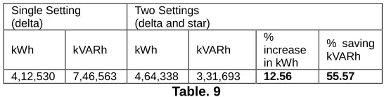
Annual Total 4,12,530 7,46,563
Table. 8
31 Table. 9
Note: Percentage increase / saving is with respect to single setting.
CONCLUSION
Detailed analysis of performance of the induction machine in the delta and star settings has been presented. It is shown that the machine can be designed for a given voltage and power rating to operate with delta for above 40% rated load and then switched to star at reduced load conditions for improving power factor and efficiency. This has been demonstrated with experimental results on a three-phase, 4-pole, 50 Hz, 400 V, 3.70 kW induction machine. Both predetermined and experimental results obtained on the induction machine are presented. Further, it is of interest to predetermine the quantum of improvement in power factor when the induction machine is switched to star connection from delta
REFERENCES
[1] N. Mohan, ―Improvement in energy efficiency of induction motors by means of voltage control‖, IEEE transaction on Power apparatus and systems, Vol. PAS-99, No. 4, July/ August 1980, pp.1466-1471.
[2] A. Abdel-halim, A.F. Almarshoud, and A.I. Alolah, ―Performance of grid-connected induction generator under naturally commutated ac voltage controller‖, Electric Power Components and Systems, Vol.32, No.7, July 2004, pp.691-700.
[3] Hideo Tomita and Toshimasa Haneyoshi, ―An optimal efficiency control for energy saving of ac motor by thyristor voltage controller‖, IEEE international conference IECON 1988, pp.816-819.
[4] N. Kumaresan , N.Ammasai Gounden, M.Subbiah, T.R. Selvakumar, ―A Thyristor controller for energy conservation in three-phase Induction motors‖, Fifth international conference on electrical rotating machines, ELROMA-99, 25th and 26th January 1999, Mumbai, pp.1-8.
[5] S.A. Hamed, B.J. Chalmers, ―Analysis of variable voltage thyristor controlled induction motors‖, IEE proceedings, Vol.137, Pt.B.No.3, May 1990, pp. 184-193.
[6] M.G. SAY, ―Alternating current machines‖, The English Language Book Society and Pitman publishing, Edinburgh, UK, 1976.
[7] N. Kumaresan and M. Subbiah, ―Innovative reactive power saving in wind-driven grid-connected induction generators using a delta-star stator winding: part I, Performance analysis of the delta-star generator and test results‖, Wind Engineering, Vol.27, No.2, 2003, pp.107 –
120.
[8] N. Kumaresan and M. Subbiah, ―Innovative reactive power saving in wind-driven grid-connected induction generators using a delta-star stator winding: part II, Estimation of annual Wh and VARh of the delta-star generator and comparison with alternative schemes‖, Wind Engineering, Vol.27, No.3, 2003, pp.195-204.
[9] S. Sudha, N. Ammasaigounden and M. Subbiah ―A thyristor controller for power factor improvement of wind-farm induction generators‖, pp. session V-19-26, Proceedings of the Fourth International Seminar on Power Electronics & Automation ELECRAMA-99, IEEMA, Mumbai, India, 1999.
[10] M.A. Abdel-Halim, ―Solid-state control of a grid connected induction generator‖, Electric Power Components and systems, Vol.29, 2001, pp. 163-178
BIOGRAPHIES
Mr. Ramesh Daravath was born on 03.07.1986 in Hyderabad, Telangana, India. He got his M.Tech degree in Power electronics from National Institute of technology, Tiruchirapally in 2010. He is presently an Assistant Professor in the department of Electrical and Electronics Engineering in Gitam University. His field of interest is recent role of power electronics devices in power system operation, control & stability and renewable energy sources
Mr. Lakshmaiah katha was born on 15.07.1984 in Hyderabad, Telangana, India. He got his M.Tech degree in Industrial Electronics from National Institute of technology, Surat, Gujarat in 2009. He is presently an Assistant Professor in the department of Electrical and Electronics Engineering in Gitam University. His field of interest is recent role of power electronics devices in power system operation, reduction of harmonics in power electronics controller and renewable energy sources
Mr. Ch Manoj Kumar was born on 17.08.1994 in Hyderabad, Telangana, India. He is presently a student in the department of Electrical and Electronics Engineering in Gitam University.
Single Setting (delta)
Two Settings (delta and star)
kWh kVARh kWh kVARh
% increase in kWh
% saving kVARh
32 Mr. AVS Aditya was born on 19.05.1996