IJSRST1841068 | Received : 12 Oct 2018 | Accepted : 24 Oct 2018 | September-October -2018 [ 4 (10) : 280-296]
Themed Section: Science and Technology
280
Analysis of PMSG-Based Wind Power Generator Performance
under Faults
M. Venkata Gowtham1, P. Sujatha2
1P.G Scholar, Dept. of Electrical & Electronic Engineering, Jawaharlal Nehru Technological University,
Anantapur A.P. India
2Professor, Dept. of Electrical & Electronics Engineering, Jawaharlal Nehru Technological University,
Anantapur A.P. India
ABSTRACT
Fuzzy logic control of a full-scale permanent magnet synchronous generator (PMSG) based wind turbine with dc-link voltage control through the machine-side converter can possibly give inherent low-voltage ride-through (LVRT) execution without extra equipment parts. In any case, a few essential execution aspects identified with this topology are not tended to in this writing. This paper examines the effects of the LVRT control on the stability and risk of resonance, effective operation, and exhaustion in a full-scale PMSG-based wind power generation system. An analytical model, considering the double mass nature of the turbine generator and commonplace LVRT prerequisites is created, approved, what's more, used to describe the dynamic execution of the wind generation system under LVRT control and practical generator characteristics. To upgrade the operation and reduce the exhaustion under LVRT control, two solutions, in view of dynamic damping control and dc-link voltage transmission capacity retuning, are proposed, dissected, and thought about. Keywords : Low-voltage ride-through (LVRT), PMSG, Fuzzy Logic Controller (FLC), DFIG, Wind Energy Conversion System (WECS), PI Controller.
I.
INTRODUCTIONWIND TURBINES innovation has turned out to be exceptionally best in class with the goal that wind power is considered as a noteworthy green source in modern power systems. In this manner, the penetration level of wind power generation is expanding quickly without any signs of slowing down. While the traditional issues of wind power, for example, removing the greatest accessible wind power, have been illuminated; the expanded penetration level of wind power is making new issues for power systems. Consolidating wind power generators in frequency regulation and low-voltage ride thorough (LVRT) are among these major issues. Frequency regulation has
increased huge consideration in the writing in late years [1],and grid codes for LVRT have been institutionalized furthermore, actualized in a few nations.
International Journal of Scientific Research in Science and Technology (www.ijsrst.com)
281
under LVRT. In spite of the fact that the crowbar strategy is broadly used in DFIGs [5], it is described by the loss of control and the waste of energy. As an option, the demagnetizing control strategy has been proposed; be that as it may, it has not been generally adopted because of its complexity.
Every one of these challenges, other than some different issues, for example, reliability, losses, and the cost of slip rings and gearboxes, decrease the benefits of DFIGs and result in an expanding pattern toward utilizing direct-drive permanent magnet synchronous generators (PMSG) with full scale back- to-back converters [9]. Not with standing, this topology with conventional control (i.e., dc-link voltage control by means of the grid side converter) yields high dc-link voltage during fault conditions. A few methodologies have been proposed to conquer this trouble. Reference proposes the utilization of a breaking resistor to dissipate excessive dc-link energy; be that as it may, this technique expands the losses. The utilization of the rotating mass of a wind generator for storing the excessive generation during the fault is proposed in. The destinations of these investigations were to not just upgrade the dc-link voltage dynamics during the fault, but also to improve different aspects of the grid voltage even under asymmetric faults [3-4]. The aftereffects of these investigations are promising and introduce the PMSG as a generator with a natural LVRT ability without the requirement for any extra segments. Be that as it may, the double mass nature of the turbine-generator mechanical dynamics and its relatively soft shaft characteristics are not considered in these works.
The natural resonance of PMSG-based wind power generators under conventional conditions has been explored altogether [5]. Strangely, a portion of the most punctual articles in this field have brought up the danger of reverberation and proposed moderation procedures. As it were, adopting a realistic double mass model for a PMSG-based wind turbine is essential since utilizing the single-mass model can
prompt an incorrect and deceptive evaluation of LVRT operation. On the other hand, using the rotating masses in a PMSG for storing the excessive energy during the fault will explore its shaft to the power system transients. Considering the delicate quality of a direct drive PMSG shaft, the LVRT control scheme may expand the fatigue and speed up the aging of the wind generator [11].
Recently, it has been discovered that wind generators Suffer from faster aging than expected, mostly as a result of mechanical fatigue. In spite of the fact that tending to the exhaustion caused by wind speed variation has increased noteworthy consideration the effect of faults on the LVRT capable PMSG fatigue is not tended to in the present writing. For conventional synchronous generators, the impact of power system faults on the generator fatigue is altogether tended to in the writing. It has been demonstrated that these faults increases the stresses and wear the generator faster. Indeed, even DFIGs, which as a rule receive crowbars during a fault, have been examined for possible mechanical tensions.
To describe the advantages and disadvantages of the LVRT-capable control technique, detailed modeling and thorough analysis are required. This paper researches the effects of the LVRT control on the stability of wind power generator and risk of resonance in its mechanical drive, successful operation during faults, and fatigue in a full-scale PMSG-based wind power generation system [10-12]. A diagnostic model considering the double mass nature of the turbine/generator and normal LVRT prerequisites is produced, approved, and used to describe the dynamic performance of wind generation system under LVRT control and practical generator characteristics.
International Journal of Scientific Research in Science and Technology (www.ijsrst.com)
282
transmission bandwidth re-tuning, are proposed and analyzed. The fundamental commitments of this paper to the field are
1) Providing a three-stage small signal model for a PMSG based wind generator to dissect the fault ride-through dynamics by considering the double mass mechanical dynamics and LVRT characteristics. 2) Investigating the stability risk of resonance, and successful operation of a PMSG-based wind power generator under LVRT.
3) Studying the effect of the LVRT control on the generator fatigue.
4) Studying and comparing at the performance of two possible solutions for execution improvement and fatigue decrease in a PMSG-based wind generator with LVRT.
II.
MODELINGTraditionally, the grid- side converter (GSC) is used to direct the dc-link voltage while the wind generator-side converter (WSC) removes the maximum available power. During a fault, the GSC loses its capability to inject or sink active power, practically or completely; in this manner, a voltage violation may happen in the dc-link voltage. On the other hand, to use the generator rotating mass for storing away the excessive energy during a fault, switching the control elements of the WSC and GSC has been proposed.
Fig. 1. PMSG-based grid-connected wind power generator.
This switching could be either permanent or, only temporary during faults. In this paper, the performance of a LVRT-capable PMSG-based wind generator in which the control functions of the WSC and GSC are permanently switched is analyzed. It is
easy to show that no difference exists in the conduct of a PMSG-based wind generator under ordinary operating conditions with the dc-link voltage regulated by either the GSC or the WSC.
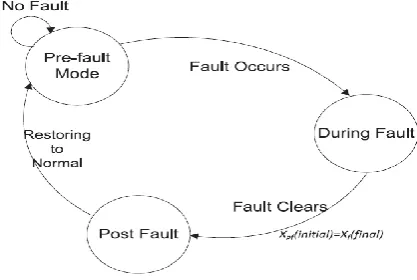
Fig. 2. Schematic view of the LVRT modeling approach.
International Journal of Scientific Research in Science and Technology (www.ijsrst.com)
283
modes and the corresponding linearized models will be talked about in the following sections.
A. Pre-Fault
This state can be recognized as a typical working condition, be that as it may, it has a noteworthy normal component with the "during fault" period. In fault, when the WSC controls the dc-link voltage, the WSC and thus the generator, in both normal and fault conditions, work comparably to manage the dc-link. The GSC performance during fault conditions, a work similar to dc-link.
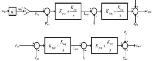
Fig. 3. Block diagram of the Wind side controller.
To support the closed control of a PMSG, a FOC control system is used in the d-q reference frame is as a rule utilized. This frame links the q-axis current iq with the active power estimation, though the reactive power is needy on the d-axis current part id, which is more frequently than not controlled to zero. The reference of the q-axis current part is produced to control the dc-link voltage, VDC, as shown by (1),
where Kp and Ki are the proportional-integer (PI)
regulator parameters, and the "ref" subscript signifies the desirable value:
( ) (1)
(2)
The current reference is compared with the actual current values and it can feed to PI current controller as shown in Fig. 3. Much of the time, the current dynamics, the relation between the actual and desired q-axis currents can be estimated by (2), where Τi is the
closed loop current control time-constant. This
current is identified with the electromagnetic torque by (3), where Tg, P, and λm are the electromagnetic
torque, pole pair number, and the electromagnetic flux constant of a PMSG, respectively:
(3)
(4)
On the one hand, the electromagnetic torque impacts the dc link voltage by means of the generator electric output power Pgen, as given by (4), where ωg is the
rotational speed of the generator. Condition (5) relates the PMSG output power and GSC output power, Pgrid
to the dc-link voltage, where C and Pnom speak to the
dc-link capacitance and nominal power. Pgen and Pgrid
here are in per unit though alternate parameters have their well known SI units (Watt, Farad, and Voltage)
( ) (5)
On the other hand, Tg is an essential variable in the
mechanical some portion of the generator as appeared by (6)– (8), where H, T, Ks , D, θ, and ω speak to the
inertia constant, torque, shaft stiffness, damping factor, shaft angle and rotating speed, individually; and
Fig. 4. Block diagram of the Grid side controller.
Subscripts B, 0, t, and g denote the base, initial, turbine, and generator, respectively. Obviously, the initial values of the torques and speeds of the generator and turbine are the same
(6) ( ) (7)
International Journal of Scientific Research in Science and Technology (www.ijsrst.com)
284
The wind turbine execution can be depicted by (9), where ρ is the air density; CP is the power coefficient
of the wind turbine; λ is the tip ratio; θ is the pitch angle; Ar is the effective area covered by the turbine
blades; β is the pitch angle; VW is the wind speed; and
Pm is the mechanical input power and is equal to the product of Tt and ώt,
(9)
(10)
In ordinary working conditions, the reference grid power is set to separate the most extreme available power, as Fig. 4 appears. Reference demonstrates that if the pitch angle is always kept at zero, this ideal power can be communicated by (10) in which KOPT is a constant. The GSC controller is fast enough to assume that the actual amount of Pgrid is equal to its reference value. In a double mass mechanical system, resonance is possible; in this manner, an active damping controller can be utilized to suppress resonance without the physical losses related with a passive damping solution. To finish the model, a typical active damping controller is augmented in the system dynamics. Condition (11) portrays the active damping technique, at first recommended. Fundamentally, it is a band-pass filter aiming to increment the damping of the natural resonance frequency, ωad, of the generator. This damping can be disposed of just by allocating Dv, the active damping gain, to zero. In (11), Vnom is the nominal dc-link voltage. The utilization of the active damping in both normal and fault situation will be talked about later. (11)
To build the final model, the system dynamics need to be linearized; however because of lack of space, this step is not detailed here not point by point here except when it has introduced the new states or parameters, for example, (12)– (15), where Δφ1 , Δφ2 , Δφ3 and Δφ4 are acquainted with acknowledge (11) and (1). The adjustment in the mechanical input power, ΔPm, all in general is a function of the pitch angle, rotor rotational speed and wind speed. Nonetheless, the pitch angle is normally zero, and due to the maximum power point tracking (MPPT), dPm/dωt = 0. Along these lines, the mechanical power can be communicated as a single variable function of the wind speed as in (16). The linearization point in the modeling is the system's equilibrium point, which is a function of wind speed (12)
(13)
(14)
(15)
International Journal of Scientific Research in Science and Technology (www.ijsrst.com)
285
B. During Fault
During the fault, a model change is required, due mostly to the inability of a wind power generator to inject the available wind power to the system.
√ (18)
In this manner, the main difference here is the grid power, which can never again be described by (10). Since any point over these two lines ought to be endured by the generator, the fast recovery speaks to a scenario where the line voltage is restored to an area of 10% voltage deviation directly after 150 ms for this situation, the active power injection is not limited by
the reactive power mandate and the system is not in the "During fault" condition after a short time interval. In the slow recovery, the limit line 1 is considered where the voltage is increasing linearly with time, thus after 900 ms, the required reactive power injection is decreasing linearly. Condition (19) at bottom of the page demonstrates the system model under the fault condition. This model receives the final equilibrium point of the per-fault stage as the linearization point. Also, the ac-system is thought to be strong enough so that the interaction of the ac-system with the wind generator after fault recovery can be neglected.
C. After Fault Clearance
After the time instant indicated by t* implies that (17)
is yet again substantial to describe the system; however, it is not in its equilibrium point any more. This initial point could be easily extracted from the past part. At the end of the day, the last states of the fault part could be utilized as initial values for this mode. To simply the model, the wind speed changes could be overlooked here. At that point this mode could be comprehended as an initial value response.
D. Model Verification
To approve the proposed demonstrate, a typical 2.0 MVA PMSG based wind turbine is simulated for detailed gritty time-domain simulation studies. The
turbine and generator parameters are given in the Appendix, and the controllers are depicted in Figs. 3 and 4. The time-domain simulation model uses a well-tuned phase locked loop (PLL) as well. The proposed model and the time-domain simulation model have similar parameters and are excited by a three-phase solid fault happening at the point of common coupling.
III.
DOUBLE-MASS PMSG AND LVRTInternational Journal of Scientific Research in Science and Technology (www.ijsrst.com)
286
generator system control parameters. The analysis and solutions displayed in this segment illustrate the usefulness of utilizing the proposed analytical model.
A. Successful LVRT Operation
A conventional PMSG-based wind generator ordinarily has no active or passive damping system. Consequently, numerous specialists have talked about the risk of resonance in these generators, particularly on account of the relatively soft shaft dynamics [7]. In fact, the active damping presented in (11) is one of the arrangements talked about to solve this issue. In any case, has demonstrated that an electromagnetic torque with positive derivative as for the generator speed (dTg/dωg = 2KOPTωg > 0) is sufficient to ensure the
generator stability. In typical circumstances where the GSC and WSC active powers are equal, the generator torque is equal to KOPTω2g. In this way, the MPPT
produces a stabilizing torque in the generator, and additional remedy is necessary.
1) Problem Description: The positive dTg/dωg
condition can absolutely change if a fault happens. During faults, Pgrid is reduced to zero, and the
generator never again takes after the MPPT control. Despite the fact that the WSC can in any case direct the dc-link, the risk of instability in the mechanical system of the generator exists. Utilizing the pre-fault model for the post-fault situation infers that the system stability before a fault ensures the stability after the fault clearance. In this manner, to the conditions that the generator experiences during the fault, the generator will be restored to its pre-fault status if it were a steady point. Be that as it may, the circumstance is considerably more complicated. In reality, some relays will separate the generator if the observed parameters violate their allowed range. Stability, as well as the system limitations ought to not be abused. The system designer must check the limit violation as well.
The soft shaft of the mechanical system does not allow equal involvement of both rotating masses in storing energy. The generator rotating mass, which is more controllable, stores a larger portion of excessive energy than what is stored in a system with a stiff shaft, or equivalent, with a single-mass model. Nonetheless, this mass is generally substantially lighter than the turbine mass. A single mass show predicts parallel changes in the angular speeds of the masses, and thus, division of the excessive energy between them will be founded on their inertia. The energy stored in a rotating mass is a function of the square of its angular speed, ω, and its inertia H.
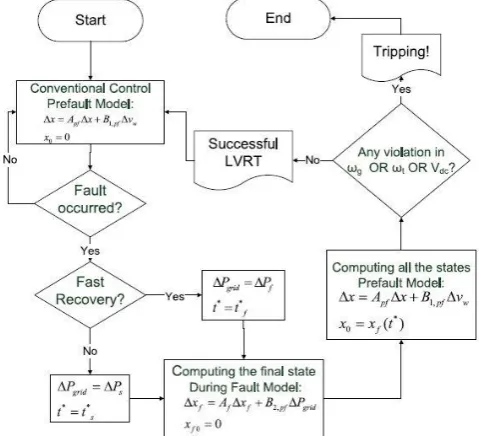
Fig. 5. Flowchart of the complete LVRT model.
International Journal of Scientific Research in Science and Technology (www.ijsrst.com)
287
can lead to deceiving LVRT capability results. This essential finding is missing in the present writing supporting the LVRT control method for PMSG-based wind generators.
2) Remedy: To stabilize the system during the fault and control the states, the dc-link voltage control bandwidth, as one of the officially accessible control levers, can be utilized. The dc-link voltage control bandwidth fdc can be calculated, as given by (20), by expecting a fast current controller, i.e., a small enough τi. The Kic parameters can be adopted to control fdc,
√
(20)
A smaller bandwidth implies that the controller is slower, and a wind generator is not responding to changes rapidly. In other words, now the dc-link should assume the part of a buffer that does not allow the generator to be presented to quick changes. In this case, fault transisents will be suppressed by the dc-link slow dynamics instead of being directly imposed on the rotating masses of the generator. This real part of the dc-link in stabilizing the system under faults is interestingly with the philosology of LVRT in a PMSG-based wind generator, in which the rotating mass of the generator is favored over the dc-link to store the excessive energy. From one perspective during a fault, the system turns out to be incidentally unstable, and there is no control of the energy management between sources.
B. Fatigue Analyses
Scientists comprehended the significance of fatigue analysis of power generators a generally long time ago back. In the writing, fatigue is related with the notigue of stress. At the point when the stress is higher than a specific point of confinement, the shaft material deforms irreversibly, and this nonreversible deformation can be interpreted as fatigue. Then again, this outcome additionally infers that under that at a
certain stress limit, the shaft stays in the elastic stress region, furthermore, the machine experience no faster aging. A machine in this condition has not yet achieved its fatigue limit, which depicts the most maximum stress that does not result in an fatigue. Inspite of the fact that the shaft stress is a linear function of the shaft torque, the relation of fatigue and the shaft torque is significantly more complicated. The connection of stress and strain makes hysteresis cycles, what's more, to calculate the impact of stress on the fatigue, the maxmimum stress, avg stress and number of each cycle during a generally long time should be calculated. The strategy utilized is very nonlinear, cumulative and complicated. After some further calculation, it can be detailed as
(21)
Clearly, the fatigue estimation, F, is a function of the shaft torque and its subsidiary. The positive parameters a and g are ascertained on the web, and, due to the cumulative nature of fatigue, they vary after some time. From one viewpoint, the shaft torque and its derivative can be utilized as lists for the fatigue investigations. Then again, restricting the mechanical tensions can keep them from including to the generator fatigue. In this way, the shaft torque and its derivative can be gauged and controlled to limit shift fatigue.
International Journal of Scientific Research in Science and Technology (www.ijsrst.com)
288
mechanical stresses are considerably higher. Actually, in an expectedly controlled PMSG-based wind turbine, significantly less and, ideally, no, tensions are induced on the shaft of the generator because of power system faults. A conventional generator continues to separate the maximum available energy from wind regardless of faults, and every one of the tensions should be handled by the dc-link capacitor and GSC.
Along these lines, the LVRT control strategy eliminates the requirement for new segments to dissipate the excessive energy during the fault, yet this technique can expand the aging of the generator. The mechanical stress can be reduced by means of active damping control or dc-link voltage control bandwidth re-tuning, however at the cost of higher stress on the dc-link capacitors. This mechanical stress issue, related arrangements, and tradeoffs are not addressed to in the literature.
2) Remedy: The active damping control is analyzed here as well. Considering that the dc-interface capacitors are the weakest segments in power converters, a system designer can be faced with a strong trade-off. On the one hand, with either no or a small amount of active damping, the dc-link capacitor does not encounter any serious overvoltage, however, the turbine-generator shaft destroys all the more rapidly. Then again, the active damping controller can decrease or eliminate with the mechanical stresses at the cost of destroying the dc-link capacitor. Such issues can confine the effectiveness and adoption of the LVRT-capable control strategy for PMSGs [8-9].
a) Impact of Fault Duration: In a fast recovery, the fault clears relatively quickly. This circumstance is alluring; in any case, the fault clearance acts as another disturbance stimulating the resonance of the mechanical system once more. The clearance distribution might add to the past distribution, the fault itself, which made mechanical oscillations in any
case. These starting oscillations are not normally totally damped some time recently the fault clearance. Despite what might be expected, in the slow recovery situation, the mechanical system has more opportunity to be damped prior to the second disturbance, or the fault clearance.
b) Impact of Unsymmetrical faults: Unsymmetrical faults are not more often than not as extreme as symmetric three-phase to-ground faults (at a similar area), however they happen all the more frequently in typical power systems. On account of the accumulative nature of fatigue, they can assume play an important role in wearing out generator. The principle contrast in the unsymmetrical fault condition is just in the "during fault" stage, where the input grid power for the most part does not go to zero, and rather, a moment arrange second-order power is superimposed on the average value of Pgrid. These
facilitations disappear when the fault clears.
Fig 6. System under study
IV.
FUZZY LOGIC CONTROLLERInternational Journal of Scientific Research in Science and Technology (www.ijsrst.com)
289
engine, rule base and defuzzifier.
Fig. 7. Fuzzy Logic Controller
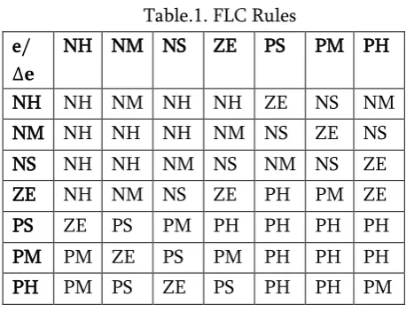
The fuzzy variables are expressed by linguistic variables they are Negative High (NH), Negative Medium (NM), Negative Small (NM), Zero (ZE), Positive Small (PS), Positive Medium (PM), Positive High (PH) for all input and output variables. The rules are set based upon the knowledge of the system and the working of the system. The rule base adjusts the duty cycle for the PWM of the inverter according to the changes in the input of the FLC.
The number of rules can be set as desired. The numbers of rules are 49 for the seven membership functions of the error and the change in error (inputs of the FLC) and control output.
Table.1. FLC Rules e
NH NM NS ZE PS PM PH
NH NH NM NH NH ZE NS NM NM NH NH NH NM NS ZE NS NS NH NH NM NS NM NS ZE ZE NH NM NS ZE PH PM ZE PS ZE PS PM PH PH PH PH PM PM ZE PS PM PH PH PH PH PM PS ZE PS PH PH PM
Fig. 8. Control Surface
The above fig.8 represents the control surface of the fuzzy logic controller output with respect to inputs error and change in error.
V.
SIMULATION RESULTSThe 3-ph ground faults are used to study this system and the fault occurs at bus 4 at after t=38s in all cases. Here we are considering a severe fault close to the wind generator allows for observing the worst-case scenario.
A. Shaft Stiffness
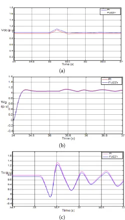
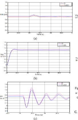
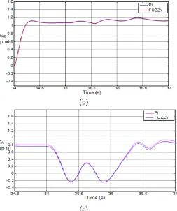
The shaft stiffness and weight ratio of the rotating masses are changed to study the analytical results. The slow recovery scenario is adopted here, where the active power injection of the GSC is forced to follow the slow recovery scenario, to examine the worst-case scenario. The results are shown in Fig.8a, 8b, 8c. While these changes do not impact the dc-link voltage, the generator rotating mass can experience a 30% over speed .Meanwhile, the turbine rotating speed does not exceed 1.18 pu. The changing parameters are Hg/Ht=0.125, Ks=1.6 pu, Ks=1.2 pu, Hg/Ht=0.07. The
International Journal of Scientific Research in Science and Technology (www.ijsrst.com)
290
(a)
(b)
(c)
Fig.8A. Impact of doubly-mass model specifications when a slow recovery occurs after fault: (a) DC-link voltage. (b) Generator rotating speed. (c) Turbine
rotating speed, with changing parameter Hg/Ht=0.125,Ks=1.6pu
(a)
(b)
(c)
Fig. 8B. Impact of doubly-mass model specifications when a slow recovery occurs after fault: (a) DC-link voltage. (b) Generator rotating speed. (c) Turbine rotating speed, with changing parameter Ks=1.2pu
(a)
(b)
(c)
International Journal of Scientific Research in Science and Technology (www.ijsrst.com)
291
B. DC-Link Controller Bandwidth
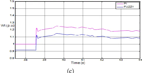
A fast recovery scenario is also tested; the results are shown in Fig. 9A, 9B, 9C, 9D. As predicted by the theoretical analysis, a lower dc-link voltage control bandwidth reduces the amplitude of oscillations on the rotating masses speeds at the cost of larger changes in the dc-link voltage. The figure also depicts the mechanical tensions and how using the dc-link as a buffer can save the generator shaft from higher stresses. Although the stress on the mechanical system of the generator is reduced, the capacitor will wear out faster. The changing parameters are BWdc=5Hz,
BWdc=0.075Hz, BWdc=1Hz, BWdc=2Hz. The results are
followed as fig. 9A, 9B, 9C, 9D. with fuzzy and PI controller comparisions.
(a)
(b)
(c)
Fig.9A. Impact of dc-link controller bandwidth when a fast recovery occurs after fault (a) DC-link voltage. (b) Generator rotating speed. (c) Torque of shaft. With
changing parameter BWdc=5Hz
(a)
(b)
(c)
Fig. 9B. Impact of dc-link controller bandwidth when a fast recovery occurs after fault a)DC-link voltage(b) Generator rotating speed. (c) Torque of shaft. With
International Journal of Scientific Research in Science and Technology (www.ijsrst.com)
292
(a)
(b)
(c)
Fig. 9C. Impact of dc-link controller bandwidth when a fast recovery occurs after fault a) DC-link voltage (b) Generator rotating speeds. (c) Torque of shaft. With
changing parameter BWdc=1Hz
(a)
(b)
(c)
Fig. 9D. Impact of dc-link controller bandwidth when a fast recovery occurs after fault a)DC-link voltage(b) Generator rotating speed. (c) Torque of shaft. With
changing parameter BWdc=2Hz
C. Active Damping
International Journal of Scientific Research in Science and Technology (www.ijsrst.com)
293
(a)
(b)
(c)
Fig.10A. Impact of the active damping when a slow recovery happens after fault; (a) DC-link voltage. (b) Generator rotating speed. (c) Torque of shaft. With No
Active Damping.
(a)
(b)
(c)
Fig. 10B. Impact of the active damping when a slow recovery happens after fault; (a) DC-link voltage. (b) Generator rotating speed. (c) Torque of shaft. With
Dv=1 pu.
(a)
International Journal of Scientific Research in Science and Technology (www.ijsrst.com)
294
(c)
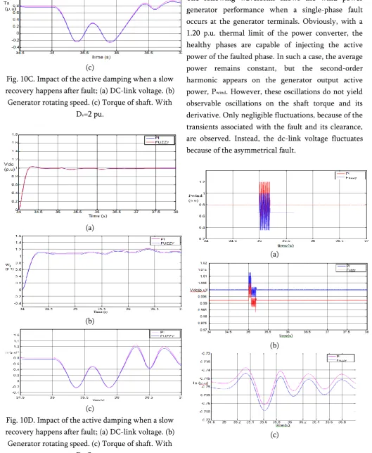
Fig. 10C. Impact of the active damping when a slow recovery happens after fault; (a) DC-link voltage. (b) Generator rotating speed. (c) Torque of shaft. With
Dv=2 pu.
(a)
(b)
(c)
Fig. 10D. Impact of the active damping when a slow recovery happens after fault; (a) DC-link voltage. (b) Generator rotating speed. (c) Torque of shaft. With
Dv=3 pu.
D. Asymmetric Fault
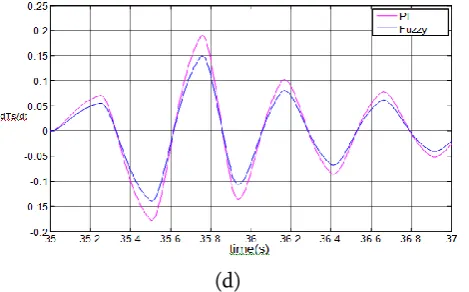
The following waveforms shows the wind power generator performance when a single-phase fault occurs at the generator terminals. Obviously, with a 1.20 p.u. thermal limit of the power converter, the healthy phases are capable of injecting the active power of the faulted phase. In such a case, the average power remains constant, but the second-order harmonic appears on the generator output active power, Pwind. However, these oscillations do not yield
observable oscillations on the shaft torque and its derivative. Only negligible fluctuations, because of the transients associated with the fault and its clearance, are observed. Instead, the dc-link voltage fluctuates because of the asymmetrical fault.
(a)
(b)
International Journal of Scientific Research in Science and Technology (www.ijsrst.com)
295
(d)
Fig. 11. Impact of a single-phase fault that occurs at the generator terminal: (a) Output power of wind generator. (b) DC-link voltage. (c) Torque of shaft. (d)
Derivative of torque of shaft.
VI.
CONCLUSIONThe modeling and analysis of a direct-drive PMSG-based wind power generator during fault and post-fault conditions were presented in this paper. An analytical multi-mode model, considering the double-mass nature of the turbine/generator and typical LVRT requirements was developed and validated against the detailed nonlinear time-domain simulation results. The model was successfully used to conduct a detailed analysis to characterize the generator performance under LVRT control, and to tune the control system parameters. The analysis showed the following.
1) Using the rotating masses for storing the excessive energy during the fault can lead to over-speeding the generator.
2) An LVRT-capable PMSG can be subjected to mechanical stresses and, accordingly, faster aging, due to electrical system faults.
3) The use of the active damping method reduces the mechanical tensions at the cost of increasing the electrical stress on the dc-link capacitor.
4) The use of the dc-link voltage control bandwidth retuning reduces the mechanical stresses; however, it yields a higher electrical stress on the dc-link
capacitor as compared to the active damping methods.
The waveforms which we got from the simulation results are the comparison of both power systems using PI control and Fuzzy control and we can clearly conclude that the power system with fuzzy control has attained the stability more faster as compared to PI control.
VII.
APPENDIXGenerators:
DG1 (wind generator) parameters [6],[13] Specifications Rating
Pole pairs 2MVA 32 Mechanical system HG HT DG DT Ks 0.53s 4.27s 0 0 1.6pu/elec.rad
DC-link Cdc
Vdc
120mF 1.8kV Controller Regulator
Parameter s
(SI units)
Kp=0.02
Ki=100
Ti=0.3ms
DG2 (Synchronous generator) parameters Specifications Rating 2.5MVA Mechanical System
(Non- reheat Thermal Turbine [11],[12]) Droop gain TCH TG H 80 pu 450 ms 0.08 s 3 s AVR parameters KA
TA
International Journal of Scientific Research in Science and Technology (www.ijsrst.com)
296
VIII.
REFERENCES
1. M F. M. Arani and Y. A. I. Mohamed, "Assessment and Enhancement of a Full-Scale PMSG-Based Wind Power Generator Performance Under Faults" IEEE Trans. On Energy conversion, pp. TEC-00524-2015. 2. S M. Muyeen, R. Takahashi, T. Murata, and J.
Tamura, "A variable speed wind turbine control strategy to meet wind farm grid code requirements," IEEE Trans. Power Syst., vol. 25, no. 1, pp. 331-340, Feb. 2010.
3. V Yaramasu, B. Wu, S. Alepuz, and S. Kouro, "Predictive control for low-voltage ride-through enhancement of three-level-boost and NPC-converter-based PMSG wind turbine," IEEE Trans. Ind. Electron., vol. 61, no. 12, pp. 6832-6843, Dec. 2014.
4. S Alepuz, A. Calle, S. Busquets-Monge, S. Kouro, and B. Wu, "Use of stored energy in PMSG rotor inertia for low-voltage ride-through in back-to-back NPC converter-based wind power systems," IEEE Trans. Ind. Electron., vol. 60, no. 5, pp. 1787-1796, May 2013.
5. H Geng, D. Xu, B. Wu, and G. Yang, "Active damping for PMSG-based WECS with DC-link current estimation," IEEE Trans. Ind. Electron., vol. 58, no. 4, pp. 1110-1119, Apr. 2011.
6. V Akhmatov, "Analysis of dynamic behaviour of electric power systems with large amount of wind power," Ph.D. Dissertation, Elect. Power Eng., rsted-DTU, Tech. Univ. Denmark, Lyngby, Denmark, 2003.
7. T Ackermann ed., Wind Power in Power Systems. Hoboken, NJ, USA: Wiley, 2005, vol. 140.
8. H Wang and F. Blaabjerg, "Reliability of capacitors for DC-link applications in power electronic converters An overview," IEEE
Trans. Ind. Appl., vol. 50, no. 5, pp. 3569-3578, Sep./Oct. 2014.
9. G Chen et al., "Reliability-oriented design considerations for high-power converter modules," in Proc. IEEE 35th Annu. Power Electron. Spec.Conf., vol. 1, pp. 419-425, 20-25 Jun. 2004.
10. P. Rodriguez, A. V. Timbus, R. Teodorescu, M. Liserre, and F. Blaabjerg, "Flexible active power control of distributed power generation systems during grid faults," IEEE Trans. Ind. Electron., vol. 54, no. 5, pp. 2583-2592, Oct. 2007.
11. P. C. Kundur, Power System Stability and Control. New York, NY, USA: McGraw-Hill, 1994.
12. I. C. Report, "Dynamic models for steam and hydro turbines in power system studies," IEEE Trans. Power Appl. Syst., vol. PAS-92, no. 6,pp. 1904-1973, Nov. 1973.