Enhancement of Voltage Profile by the Performance of
PMSG-Based Wind Power Generator by Using the Fuzzy logic
Controller
V. Priyanka1, K. V. Ramana Reddy2
1Student, Gouthami Institute of technology & Management for women, Proddatur, Andhra Pradesh, India 2Assistant Professor, Gouthami Institute of technology & Management for women, Proddatur, Andhra Pradesh,
India ABSTRACT
In this work full-scale permanent-magnet synchronous generator (PMSG)-based wind turbine with dc-link voltage control via the machine-side converter has the potential to provide inherent low-voltage ride-through (LVRT) execution without any extra hardware components. However, several important performance aspects related to this analogy are not addressed in this literature. LVRT control impacts chance of resonance, stability operation, and fatigue in the PMSG-based full-scale system generation of wind power. The logical model, considered the double-mass nature of the turbine/generator and typical LVRT essentials, is developed, validated, and used to characterize wind generation system dynamic performance using generator practical characteristics and LVRT control. To make better operation and reduce the fatigue under LVRT control, two solutions, found as active damping control and dc-link voltage bandwidth retuning, are proposed, compared, and analyzed. The elaborated nonlinear results of time-domain simulation declare the exactness of developed model and with analytical results. By using the fuzzy controllers improves voltage profile with its characteristics.
Keywords : PMSG, LVRT, dc-link voltage, GSC
I.
INTRODUCTIONWind turbines technology is very advanced that’s why wind power is considered as a major green source in modern power systems generation .The usage of wind energy is increasing there is without slowing down[1]-[3]. While the classical issues with wind power, such as extracting the maximum accessible wind power, has been solved, the enhanced penetration level of wind power is creating new problems for power systems. Incorporating wind power generators in frequency regulation and low-voltage ride thorough (LVRT) are among these serious issues. Frequency regulation creates significant attention in the modern days [4]-[6] and grid codes for LVRT have been standardized and
implemented in several countries [7].Naturally, LVRT standards emphasize the need to give a wind power generator connected to the grid and to improve the voltage profile throughout low-voltage transients. In this project all the generators in wind farm are not required to allow LVRT capability [8].
of slip rings and gearboxes, reduce the advantages of DFIGs and result in an increasing trend toward utilizing permanent-magnet synchronous generators (PMSG) with dual converters of full-scale. By using double mass nature of PMSG based generator we easily estimate the LVRT requirements. Many more advantages for the PMSG based wind power generator are the excessive energy can be used to during fault condition to clear the transients. Suppose considering the soft type of direct drive PMSG shaft, the scheme of LVRT can increase the fatigue and the speed of aging of wind generator.
This paper mainly speaks about the wind power generator stability on LVRT requirements and mechanical drive resonance, operation under the faults and fatigue in PMSG-based full-scale system generation of wind power. The main theme of this paper to the field is
1) For the PMSG- based wind power generator having the three-stage small-signal model for analyzing the fault –ride through problems for taking double mass nature turbine and LVRT characteristics. 2) The operation of the PMSG-based wind generator under LVRT can investigates the stability, hazard of resonance, and successful operation.
3) The impact LVRT control on the generator fatigue can be studied.
4) The performance of two possible solutions for the PMSG-based wind power generator under LVRT can be assessment and improved, can be studied and compared.
II.
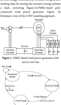
MODELINGFigure.(1) Represents the PMSG-based wind generator. It’s having the grid side converter (GSC) used to modulate dc-link voltage. Another important part is wind-generator-converter wants maximum available power. In the fault condition, the GSC losses its capability to inject or sink active power, completely; thus, a voltage violation may occur in the
dc-link voltage. Alternatively, to utilize the generator rotating mass for storing the excessive energy present a fault, switching Figure.(1).PMSG-based grid-connected wind power generator. Figure. (2) Schematic view of the LVRT modeling approach.
Figure 1. PMSG-based wind power generator with active crow bar
Figure 2. Scheme view of the LVRT modeling approach
can be not the simple thing. The figure.2 represents the schematic view of the LVRT modelling approach.
A. Pre-Fault:
The name for the pre-fault condition is normal condition. Some similarities in during fault condition in the features. Always WSC controls the dc link voltage. If it is normal or fault condition WSC can regulate the dc-link. But the GSC performance in the fault condition different dynamics and disturbances imposed on the on the dc-link.
To facilitate the close control of PMSG, a field-oriented control system implemented in the d-q reference frame is usually employed. This frame associates the q-axis current iq with the active power
production, whereas the reactive power is dependent on the d-axis current component, id.Which is usually
regulated to zero.”
B. During Fault
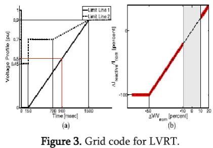
During the fault, a model modification is needed, due mainly to the inability of a wind power generator to inject the available wind power to the system. Fig. 3 clarifies the situation, presenting a typical LVRT standard [7].Fig. 3(a) shows the voltage limits for LVRT, where Fig. 3(b) shows the reactive power injection code requiring a wind power generator to reserve its entire thermal limit for reactive power injection for a voltage dip of more than 50%.
Figure 3. Grid code for LVRT.
(a) Voltage limits (b) Reactive current injection by the generator during a fault.
This requirement means that for a slow recovery (e.g., up to 900 ms),no active power can be injected into the system, and even after that occurs, the active power injection should be increased gradually to respect the grid codes and converter rating.
C. After Fault Clearance:
“
Figure. 4. Generator output power during a fault, considering fast (red) and slow (blue) recovery
scenarios.
After the time instant denoted by t∗ in Fig. 4, the GSC returns to its previous control, introduced in (10), trying to restore its initial pre-fault operating point. It means that is once more valid to describe the system; however, it is not in its equilibrium point anymore. This initial point could be easily extracted from the previous part. In other words, the final states of the fault part could be used as initial values for this mode. To simplify the model, the wind speed changes could be ignored here. Then this mode could be understood as an initial value response.”
III.
DOUBLE MASS PMSG AND LVRTA. Successful LVRT Operation
No active or passive damping mechanism for the conventional PMSG-based wind generator. The risk of resonance can be discussed by the many authors i.e. relatively about the generators especially discussed about the soft shaft dynamics. The problems are solved by the introduction of active damping. By using an electromagnetic torque equation with positive derivative for the generator speed (dTg/dωg=2Koptωg>0) it gives clarify about the stability.
1) Problem Description: If the fault occurs in the system automatically changes in the positive dTg/dωg
condition.fig.4 represents the during fault condition Pgridis reduced to zero, and the MPPT control doesn’t
followed the generator the dc link can be regulated by the WSC, the generator exists the risk of instability in the mechanical system.fig.8 represents the three-phase fault at the generator terminals before and during the fault the dominant poles location. If the system is reasonably damped it is in normal (pre-fault) condition the system is during fault condition vulnerable to resonance.
Remedy
During the fault condition stabilize the system and the state can be controlled. A smaller bandwidth means that the controller is slower, and a wind generator is not responding to changes rapidly. In other words, now the dc-link should play the role of a buffer that does not allow the generator to be exposed to fast changes. In this case, fault transients will be suppressed by the dc-link slow dynamics instead of being directly imposed on the rotating masses of the generator. This major role of the dc-link in stabilizing the system under faults is in contrast with the philosophy of LVRT in a PMSG-based wind generator, in which the rotating mass of the generator is preferred over the dc-link to store the excessive energy.”
B. Fatigue Analyses
Researchers understood the importance of fatigue analysis of power generators a relatively long time
ago. In the literature, fatigue is associated with the notion of stress. When the stress is higher than a certain limit, the shaft material will go through the plastic strain region. In this region, the shaft material deforms irreversibly, and this no reversible deformation cans be interpreted as fatigue.”
On the other hand, this result also implies that under that at a certain stress limit, the shaft remains in the elastic stress region, and the machine experiences no faster aging. A machine in this condition has not yet reached its fatigue limit, which describes the maximum stress that does not result in any fatigue.”
IV.
TIME –DOMAIN SIMULATION RESULTSTheoretical analysis can be verified from the previous sections, by using the non linear typical model Ontario, Canada-based system with the help of time domain simulation technique, are employed. DG2 means, the second unit is modeled based on the details. The system includes the droop and excitation characteristics. The systems having low X/R ratio(X/R=2) nothing but distribution systems are modeled as a lumped R-L parameters. Parallel R-L elements represent the loads for the system.
The system studied under the disturbance of a three- phase to ground fault happens at bus #4 at t=35sec in most the cases. The worst case scenario can observe near the wind generator may the fault is severe. The Matlab/Simulink can be used for study the simulation results.
A. Shaft Stiffness:
experienced by the generator rotating mass unit, because the speed of the turbine doesn’t exceed 1.18 per unit. The results in the single mass model can lead to misleading results.
B. DC-Link Controller Bandwidth:
The testing for fast recovery also over. The figure.6 shows the results, from the theoretical analysis; bandwidth reduces by using a lower dc-link voltage controller. By using the dc link voltage controller larger changes in the rotating masses speeds. The figure also describes the mechanical stresses and how to save the generator shaft from the higher stresses. By using the dc link as a buffer the capacitor will wear out faster because of the stress on the mechanical system of the generator is reduced.
C. Active Damping:
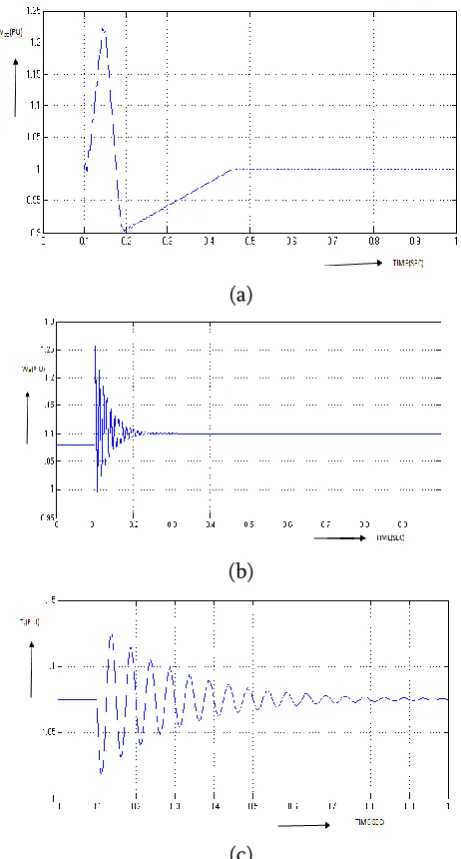
Figure.7 represents the generator characteristics for the slow voltage recovery case when the active damping is applied. Same for before onetime domain simulations gives same theoretical findings. The fluctuations are reduced by the active damping in the generator rotating mass, for the dc-link voltage speed increases with the cost of higher deviations. Figure.7 (b) represents that speed of wind is 12m/s, speed of generator rotating can exceed 1.20 per unit. This is near to the higher speed threshold of turbines. The successful LVRT yields by the active damping method and the mechanical stresses on the turbine shaft reduce, as shown in the analysis.
D. Asymmetrical Fault:
Figure .8 represents a single –phase fault occur at the generator terminals in the wind power generator. Obviously, with a 1.20 p.u.it is a power converter thermal limit, the active power is injected to the faulted phases by using the healthy phases. In this case the active power remains constant, the generator output is active power, Pwind but it has the second
order harmonic appears in the system. However, these oscillations do not yield observable oscillations
on the shaft torque and its derivative. By neglecting the fluctuations, because of the transients associated with the fault and its clearance, are observed.
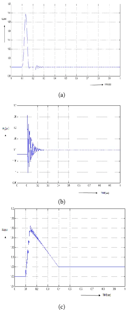
(a)
(b)
(c)
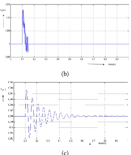
Figure 5. Impact of doubly-mass model specifications when a slow recovery occurs after fault: (a) DC-link
(a)
(b)
(c)
Figure 6. Impact of dc-link controller bandwidth when a fast recovery occurs after fault. (a) DC-link voltage. (b) Generator rotating speed. (c) Torque of
shaft.
(a)
(b)
(c)
Figure 7. Impact of the active damping when a slow recovery happens after fault;
(a) DC-link voltage. (b) Generator rotating speed. (c) Torque of shaft.
(b)
(c)
Figure 8. Impact of a single-phase fault that occurs at the generator terminal:
(a)Output power of wind generator. (b) DC-link voltage. (c) Torque of shaft.
V.
CONCLUSION
By using the PMSG-based wind power generator at different fault conditions like during fault and post fault conditions we modeled and analyze the system each and every thing present in this paper. One of the different models i.e. an analytical multi model system is considering for the double mass nature of turbine/generator and LVRT requirements for analyzing the non-linear time domain simulation results. To characterize the generator under LVRT requirements and to tune the control parameters by using this system successfully.
The following shows the analysis requirements are: 1) the excessive energy can be stored for the requirement of over speeding the generator by using the rotating mass unit. 2) Mechanical stresses in that faster aging with the faults can be subjected by using an LVRT-capable PMSG. 3) For reducing the
mechanical tensions by using active damping method for increasing the stress of dc link capacitor cost also increases.4) For reducing the mechanical stresses here by using the dc-link voltage control band width returning. Active damping method having less electrical stress compared to dc-link capacitors. The time domain simulation results are analytical results and discussions. Here by using the fuzzy controllers improve the voltage profile and active power.
VI.
REFERENCES
[1]. (2014). Global wind energy outlook.[Online]. Available:www.gwec.net
[2]. 20%Wind Energy by 2030, increasing wind energy’s contribution to U.S.Electricity Supply. Washington, DC, USA, Jul. 2008, U.S. Department ofEnergy. [3]. "Wind by numbers: Economic benefits of wind
energy," Canadian WindEnergy Association [Online]. Available:http://www.canwea.ca
[4]. S.DeRijcke, P. Tielens, B. Rawn,D.VanHertem, and J. Driesen, "Trading energy yield for frequency regulation: Optimal control of kinetic energyin wind farms," IEEE Trans. Power Syst., vol. 30, no. 5, pp. 2469-2478,Sep. 2015.
[5]. M. F. M. Arani and Y. A. I. Mohamed, "Analysis and impacts of implementingdroop control in DFIGs on micro grid/weak-grid stability," IEEETrans. Power Syst., vol. 30, no. 1, pp. 385-396, Jan. 2015.
[6]. M. F. M. Araniet al., "Implementing virtual inertia in DFIG-based windpower generation," IEEE Trans. Power Syst., vol. 28, no. 2, pp. 1373-1384,May 2013. [7]. (Apr. 2006). E. ON Netz GmbH, Grid Code: High and
Extra High Voltage,Germany.[Online]. Available: http://www.eon-netz.com
[8]. S.M.Muyeen, R. Takahashi, T.Murata, and J. Tamura, "A variable speedwind turbine control strategy to meet wind farm grid code requirements,"IEEE Trans. Power Syst., vol. 25, no. 1, pp. 331-340, Feb. 2010.
[9]. R. Cardenas, R. Pena, S. Alepuz, and G. Asher, "Overview of controlsystems for the operation of DFIGs in wind energy applications," IEEETrans. Ind. Electron., vol. 60, no. 7, pp. 2776-2798, Jul. 2013. [10]. L. Zhou, J. Liu, and S. Zhou, "Improved