Simulation and Calculation of Peak Temperature
in Friction Stir Welding Process of Aluminium
Plates
Mayur Shivajirao Patil Dr. S. A. Mastud
M. Tech Student Assistant Professor & Head
Department of Production Engineering Department of Production Engineering
VJTI, Mumbai, India. VJTI, Mumbai, India.
Abstract
The main objective of this paper work is to optimize the welding parameters such that the maximum temperature in the work piece material reaches up to 80-90% of melting point of base material in friction stir welding of aluminum plates. Friction stir welding (FSW), invented and established by The Welding Institute (TWI) in 1991 amongst the emerging new welding technologies, is used frequently for welding of high strength aluminum alloys which are difficult to weld by conventional fusion welding techniques. Friction stir welding (FSW) is a relatively new welding process that may have significant advantages compared to the fusion processes as follow: joining of conventionally non-fusion weldable alloys, reduced distortion and improved mechanical properties of weldable alloys joints due to the pure solid-state joining of metals. The study of microstructure and flow of material around the welding tool during friction stir welding (FSW) is closely linked to many of the key issues related to the process. The heat source in this model is the friction between the material and the probe and the shoulder. For understanding the FSW thermo mechanical process, the thermal history in the friction stirred weld is simulated numerically. It is necessary that the model can be further to optimize the FSW process in order to minimize peak temperature within process window. The welding process was simulated using COMSOL MULTIPHYSICS software and developed thermal profile. Modeling and simulation of FSW has been a great challenge due to the complexity of the process. The results clears that an increase in the rotational speed and coefficient of friction causes increase in the peak temperature in workpeice. The simulation result is compared to available experimental results. According to results in steady state model, when tool is at center in process the temperature is not maximum at center but slightly front of the tool, this is due to preheating in the workpeice. Keywords: Comsol Multiphysics, FSW, Steady State Model, Thermal Profile
________________________________________________________________________________________________________
I.
INTRODUCTION
Friction stir welding (FSW) is a recently emerged solid-state joining technology patented by The Welding Institute (TWI) in 1991. The process is illustrated in Fig. 1, where a rotating cylindrical shouldered tool plunges into the butted plates and locally plasticizes the joint region during its movement along the joint line that causes a join between the work pieces. In this process, the heat is originally derived from the friction between the welding tool (including the shoulder and the probe) and the weld ed material, which causes the welded material to soften at a temperature less than its melting point. The softened material underneath the shoulder is further subjected to extrusion by the tool rotational and transverse movements. It is expected that this process will inherently produce a weld with less residual stress and distortion as compared to the fusion welding methods, since no melting of the material occurs during the welding. Despite significant advances in the application of FSW as a relatively new welding technique for welding aluminum alloys, the fundamental knowledge of such thermal impact and thermo mechanical processes are still not completely understood. It is well known that the residual stress of the weld negatively affects its fatigue properties and its anticorrosion performance. Several investigations of the residual stress distribution in FSW weld were conducted by experimental methods. To gain physical insight of the FSW process and the evolution of the residual stress, the development of models and simulation techniques is a necessity. It will also be beneficial to use models and simulation techniques to minimize the residual stresses in the weld since this method will guide the implementation of the process with optimal parameters and with a minimum amount of trial-and-error. Song and Kovacevic have modeled the heat transfer in FSW using the finite difference method. Few papers have directly dealt with the modeling of the thermo mechanical stresses in FSW. [1]
induces dynamic recrystallization and recovery that refines the stir region. Therefore friction stir welded joints have improved mechanical properties such as tensile strength, ductility, hardness than conventional fusion welded joints.[2]
Fig. 1: Schematic View of the FSW Process. [3]
II.
MICROSTRUCTURAL REGIONS IN FSW WELDS
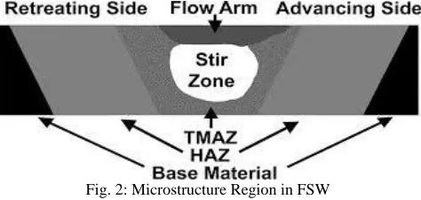
The friction stir welded joints possess four mutually distinct microstructural regions as shown in the figure-2. Starting from outside towards the center of the weld, the first region is the un-affected zone i.e. the base metal. No property or microstructural changes occur in this zone. Second region is called heat affected zone or HAZ. A very little microstructural changes used to occur in the HAZ due to the heat of welding but no plastic deformation of base takes place in this zone. The microstructure in this zone consists of coarse grained structure. The third region is thermomechanically affected zone or TMAZ. Although the TMAZ undergoes plastic deformation, recrystallization does not occur in this zone due to insufficient deformation strain but it is affected by the welding heat and considerable microstructural changes takes place in this region. The grain size in this region is found to be finer than HAZ. Fourth region which is plasticized and recrystallized due to the frictional heat produced by the action of rotating pin of FSW tool is called Nugget zone or stir zone. This region consists of very fine recrystallized equi-axed grains. [4]
Fig. 2: Microstructure Region in FSW
III.
FINITE ELEMENT MODELING OF FSW
Various FEM studies are conducted by many researchers to investigate the heat generation, residual stress and microstructure developments. Maximum temperature developed in FSW of 304L stainless steel was studied by Prasanna et.al. by using ANSYS.[6] The result of simulation shows good agreement with the experimental result and peak temperature developed was 1056.835⁰C. Biswas et.al. studied the effect of tool geometries on the thermal history of aluminium alloy 1100. They found that tool geometry with concave shoulder and conical pin was found to be preferable for FSW of AA 1100.[7]
Meshing: A.
source Q having a linear distribution of heat from the center to the outside diameter of the tool is applied to the top surface of the work piece to simulate the heat generation due to the friction. This heat source Q moves with the velocity of 1.59 mm/s along the weld line on the top surface of the work piece.
Fig. 3: Mesh Model of Workpeice
Nomenclature for Model: B.
The friction stir welding process is dominated by the effect associated with material flow and large mechanical deformation, which in turn is affected by process parameters such as
1) Rotational speed, 2) Axial force.
3) Coefficient of friction. [5]
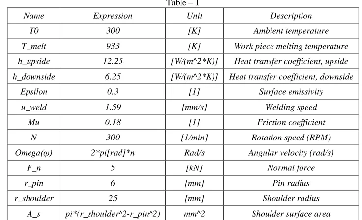
Table – 1
Name Expression Unit Description
T0 300 [K] Ambient temperature
T_melt 933 [K] Work piece melting temperature
h_upside 12.25 [W/(m^2*K)] Heat transfer coefficient, upside
h_downside 6.25 [W/(m^2*K)] Heat transfer coefficient, downside
Epsilon 0.3 [1] Surface emissivity
u_weld 1.59 [mm/s] Welding speed
Mu 0.18 [1] Friction coefficient
N 300 [1/min] Rotation speed (RPM)
Omega(ῳ) 2*pi[rad]*n Rad/s Angular velocity (rad/s)
F_n 5 [kN] Normal force
r_pin 6 [mm] Pin radius
r_shoulder 25 [mm] Shoulder radius
A_s pi*(r_shoulder^2-r_pin^2) mm^2 Shoulder surface area
The model simulates the heat generated in the interface between the tool’s pin and the work piece as a surface heat source.
=3.4 W/m^2
Here μ is the friction coefficient, rp denotes the pin radius, ω refers to the pin’s angular velocity (rad/s), and
Y (T)
is the average shear stress of the material.Additionally, heat is generated at the interface between the tool’s shoulder and the
=382004 W/m^2
Here Fn represents the normal force, As is the shoulder’s surface area, and T melt is aluminum’s melting temperature. As before, μ is the friction coefficient and ω is the angular velocity of the tool (rad/s). Above the melting temperature of aluminum, the friction between the tool and the aluminum plate is very low. Therefore, the model sets the heat generation from the shoulder and the pin to zero when the temperature is equal to or higher than the melting temperature. Figure 4 and 5 shows the resulting temperature field and isosurface in workpeice of simulation no. 2.
Fig. 4: Temperature Field In The Aluminum Plate.
Fig. 5: Isosurface of W/P.
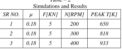
Simulations and Results: C.
Table – 2 Simulations and Results
SR NO. µ F[KN] N[RPM] PEAK T[K]
1 0.18 5 200 650
2 0.18 5 300 818
4 0.18 6 200 714
5 0.18 6 300 918
6 0.18 6 400 934
7 0.18 7 200 781
8 0.18 7 300 933
9 0.18 7 400 935
10 0.2 5 200 687
11 0.2 5 300 875
12 0.2 5 400 945
13 0.2 6 200 751
14 0.2 6 300 930
15 0.2 6 400 935
16 0.2 7 200 834
17 0.2 7 300 930
18 0.2 7 400 935
19 0.25 5 200 770
20 0.25 5 300 941
21 0.25 5 400 934
22 0.25 6 200 862
23 0.25 6 300 930
24 0.25 6 400 936
25 0.25 7 200 930
26 0.25 7 300 935
27 0.25 7 400 936
Fig.4 shows the temperature distribution across the work piece during welding. In order to verify the model, FSW experimental data published by researchers in international journals are referred here. According to Tang et al, the maximum temperature developed during FSW process ranges from 80% to 90% the melting temperature of the welding material. Here the melting point of aluminum is 933 K (660°C). The peak temperature calculated is 87% of the melting point of alloy chosen for the study.
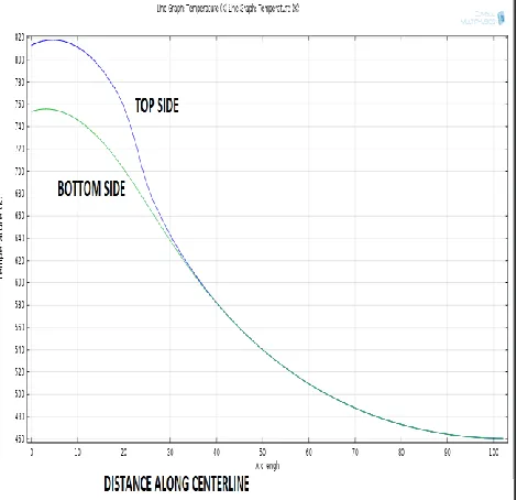
In fig. 6 graph shows relation between temperature and distance from centerline and from graph is clear that temperature is higher at top surface of plate than the bottom surface. Following fig.7 shows slice section of workpeice at center; here we see that maximum temperature in process is not in center but in front of centerline that is in the front of tool due to preheating. Here we clearly see that maximum temperature in center is 784 K.
Fig. 7: Slice Section
IV.
CONCLUSION
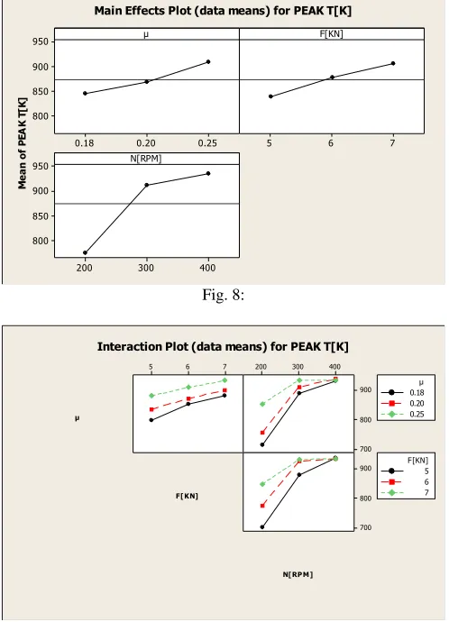
Out 27 simulations taken from COMSOL MULTIPHYSICS software, 5 are within rang of 80-90% of M.P. of base metal in FSW. Variations in process parameters by keeping the geometry same have major effects on temperature profile during FSW. From the temperature distribution results that peak temperature increases by increasing the coefficient of friction, vertical force and tool rotation. By using minitab software, main effect plot and interaction plot for peak temperature are plotted.
Fig. 8: Fig. 9 M e a n o f P EA K T [K ] 0.25 0.20 0.18 950 900 850 800 7 6 5 400 300 200 950 900 850 800 µ F[KN] N[RPM]
Main Effects Plot (data means) for PEAK T[K]
µ
F[KN]
N[RPM]
7 6
5 200 300 400
REFERENCES
[1] C.M. Chen, R. Kovacevic , ―Finite element modeling of friction stir welding—thermal and thermo mechanical analysis‖ International Journal of Machine
Tools & Manufacture 43 (2003) 1319–1326.
[2] Lee WB, Yeon YM, Jung SB. The improvement of mechanical properties of friction stir welded A356 Al alloy. Master Sci Eng 2003; A355:154-9.
[3] J.H. Hattel, K.L. Nielsen, C.C. Tutum, ―The effect of post-welding conditions in friction stir welds: From weld simulation to ductile failure‖, European
Journal of Mechanics A/Solids.
[4] Deepak Sharma1, Dr. Rajesh Kumar Bhushan, ―Thermo mechanical Modeling of FSW: A Review‖ School of Mechanical Engineering, Shri Mata Vaishno
Devi University, Katra, Jammu and Kashmir, India
[5] N. BhanodayaKiranBabu, A. Prabhu Kumar and M. Joseph Davidson , ―A REVIEW OF FRICTION STIR WELDING OF AA6061 ALUMINIUM
ALLOY‖ ,Department of Mechanical Engineering, ChristuJyothi Institute of Technology, Jangaon, Warangal, India ,Department of Mechanical Engineering, JNTUH College of Engineering, Hyderabad, India,Department of Mechanical Engineering, National Institute of Technology, Warangal, India
[6] P.Prasanna, B. Subba Rao, G. Krishna Mohana Rao; Finite element modeling for maximum temperature in friction stir welding and its validation; Int J Adv
Manuf Technol; 2010;51:925-933.