CFD Simulation of Ice Slurry Flow in Vertical Pipe
Kamal Singh Rawat
Department of Mechanical Engineering, College of Technology, GBPUAT, Pantnagar, Uttarakhand -263145, India.
Article Received: 20 September 2017 Article Accepted: 22 December2017 Article Published: 05 January 2018
1. INTRODUCTION
Due to the energy, environmental and safety challenges, demand of secondary loop refrigeration systems increases.
Refrigerant in the secondary loop system can be a single phase or two-phase fluids, however two-phase mixture as
the secondary loop refrigerant take advantage of the high latent heat during the phase change process and less
pumping power than single phase fluids. In the two-phase secondary loop refrigerants, ice slurry and carbon
dioxide shows the huge potential. Ice slurry has a high energy storage density, higher heat transfer coefficient and it
also reduces the system size (storage tank and pipelines), however carbon dioxide has some disadvantages as
two-phase secondary loop refrigerant [1]. Due to these attractive features, the ice slurry gains much attention as a
secondary loop refrigerant over other single phase fluids. Ice slurry can be defined as a dispersed ice particles in
carrier liquid (either water or binary solution of water and freezing point depressant). In the ice slurry the size of the
ice particles may vary from 0.1 mm to 1.0 mm, however smaller particle size more beneficial [2]. For the particular
applications, the initial size of the particle, concentration and configuration of carrier liquid may vary.
The dispersed ice particles make measurement and visualization of ice slurry a formidable task using experimental
techniques. However, Computational fluid dynamics (CFD) is a competent and flexible approach in order to obtain
ample information about the flow, especially velocity and particle concentration profile [5]. Some work already
done to solve such problem through CFD [3-6], however still qualitative literature is not available on modelling.
Wang et al., 2013 offered an Eulerian CFD model based on KTGF and presented velocity and ice concentration
profile in a vertical pipe [4]. However, the author ignores the effect of two interfacial forces, i.e. turbulent
dispersion and lift force [6], which are considered in the present work. In the present work, computational
investigation of the isothermal ice slurry flow has been carried out to predict the velocity and the ice particle
distribution during the upward flow in a 23 mm diameter and 2 m long vertical pipe. The properties have been
calculated for the ice slurry of a mixture of 10.3 wt % ethanol in water.
A B S T R A C T
In the last decade, ice slurry gains much attention as a two-phase secondary loop refrigerant due to its high cooling capacity and environmentally friendly nature. However the flow of ice slurry in the pipe during transportation, is a complex phenomenon as it affected by many parameters, i.e. mean velocity, ice particle size, ice concentration and type of flow etc.. In the present work, computational investigation of ice slurry flow without melting in a vertical pipe has been carried out, in order to develop the basic idea of the ice slurry flow in the vertical pipe. Euler-Euler CFD model with the kinetic theory of granular flow (KTGF) has been used to predict the velocity and the ice particle distribution during the flow. Firstly the present model is validated with existing experiment result in literature, then model is applied to the present problem. Result shows that, the ice slurry velocity profile is almost symmetric due to uniform ice fraction distribution on the horizontal cross-section at initial velocity of 1 m/s and 10% ice concentration. Apart from that, effect of different flow direction (upward and downward) on flow also investigated.
2. MATHEMATICAL MODELING
The Eulerian model considers all the phases are in continuum, that interpenetrates each other and exchange
momentum, hence this technique also known as the interpenetrating continua model. In this approach, each
conservation equation is solved for each phase separately. In this work, flow is considered to be incompressible and
ice particles are presumed to be smooth and globular in shape. The particle cohesion is ignored during the flow.
For the liquid and solid phases, the continuity equations are defined below:
(1)
(2)
In a control volume, the relation between liquid and solid fraction is given as,
(3)
Where, v, α, ρ are the velocity, volume fraction and density respectively. The subscripts l, s are for the liquid and
solid respectively.
The momentum balance for both phases is expressed as
Liquid phase:
(4)
(5)
Solid phase:
(6)
(7)
where R is interfacial force, µ is viscosity, is unit tensor and is bulk viscosity, which is the measure of solid
particles resistance to compression and expansion which is adopted from Lun et al., 1984 [7].
(8)
The solid shear viscosity based on KTGF represented as Gidaspow, 1994 [12].
Where ds, , and go,ss are the solid particle diameter, restitution coefficient, granular temperature and radial
distribution function respectively. Radial distribution is the probability of solid-solid interaction which is define as
Lun et al., 1984 [7].
(10)
Where is maximum packing limit and Ps is the solid pressure, described by the KTGF in the following
equation.
(11)
In general interfacial forces in slurry flow substantially cover lift, drag, virtual mass and turbulent dispersion
forces. The interfacial forces in the present work include lift, drag and turbulent dispersion forces, however; the
effect of the virtual force can be neglected. Drag force is described by with the help of Gidaspow, 1994 [8] and the
lift force on the solid phase is calculate in the present work as Drew et al. 1993 [9]. The interface turbulent
momentum transfer is defined using Burns et al. 2004 [10]. Turbulence modeling in the dense slurry flow is done
by per phase model as per Zhang and Shi [6].
2.1 Boundary Conditions
In the present study, modeling of isothermal ice slurry flow in vertical pipe has been carried out in a CFD software
package FLUENT 15. The boundary conditions are defined separately for both the phases at inlet, outlet and wall of
the pipe. For the inlet, velocity-inlet condition with the velocities perpendicular to the cross-section of the pipe for
both the phases and the uniform ice particle volume fraction for solid phase is specified. For the outlet,
pressure-outlet condition with zero gauge pressure is specified for both the phases. For the liquid and solid phase
no-slip condition and partial slip condition with a specularity coefficient of 0.2 are specified respectively at the pipe
wall.
2.2 Numerical Procedures
The problem domain is divided into hexahedron grid and further improved near the wall domain. In the present
work results are presented for 362,000 cells with 362 on the cross-section and 500 per unit length along the pipe.
The grid independence test was also performed, however, further refinement does not influence results
significantly. Finite volume method with SIMPLE algorithm, for coupling pressure and velocity, is applied to solve
continuity, momentum and other supporting equations discussed above. All the solutions presented here are
calculated for transient condition with time step 0.001 s and converged to residuals of 10-5.
2.3 Validation
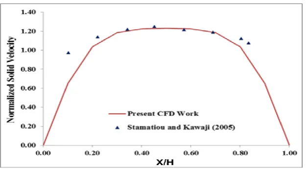
Firstly the present model is validated with existing experiment results in literature to ensure that the present model
experimental result of Stamatiou and Kawaji [11]. Figure shows the normalized velocity (in-situ velocity on
horizontal line / initial velocity) on the ordinate and normalized position of line (X/H) on abscissa. The results are
compared for the 6.2% based NaCl ice slurry with particles diameter of 0.1 mm in a 610
310
25.4 mm verticalduct at an initial velocity of 0.159 m/s and 1.9% initial particles concentration.
Fig. 1. Comparison of experimental and numerical results of slurry velocity profile in vertical pipe
3. RESULTS AND DISCUSSION
For the application of comfort cooling in buildings, ice slurry has to flow through vertical pipes during
transportation. Therefore, it is important to investigate the flow through vertical pipe to develop an efficient
transport system. In this section, computational investigations of ice slurry flow have been carried out in a 23 mm
diameter and 2 m long vertical pipe. The simulations are done at initial velocity of 1 m/s and initial particle
concentration of 10 %. The effect of the flow direction of ice slurry in the vertical pipe is also investigated.
The flow of the ice slurry in the horizontal pipe is not affected by the flow direction as the gravitational force
always acts in the perpendicular and downward direction of the flow however, in the case of vertical pipe the
direction of the flow (upward or downward) is important. Therefore, it is essential to investigate the effect of flow
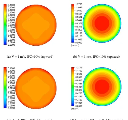
direction on pressure drop, velocity and particle distribution. Fig. 2 shows the contours of solid particle and velocity
distribution for the different flow directions at higher initial velocity of 1 m/s. The results are obtained for the 10 %
ethanol based slurry with particle size of 0.1 mm at 10% initial particle concentration.
The contours (a) and (c) show the ice particle distribution for upward and downward flow directions, respectively at
the outlet of the pipe. It can be observed from the contours (a) and (c) that the variation in the particle concentration
at the cross section is negligible and particle are homogenously distributed as gravitational force is acting in the
parallel direction of the flow. The contours (b) and (d) show the ice particle velocity distribution for upward and
downward flow directions, respectively, at the outlet of the pipe. It can be observed from the contours (b) and (d)
that the velocity distribution is symmetric at the cross section due to uniform particle distribution and higher initial
It can be observed from Fig. 4.20, that there is no significant effect of the flow direction on the velocity and particle
distribution during the ice slurry flow in the vertical pipe. However, the pressure losses are more in the downward
direction of the flow.
(a) V = 1 m/s, IPC=10% (upward) (b) V = 1 m/s, IPC=10% (upward)
(c) V = 1, IPC = 10% (downward) (d) V = 1 m/s, IPC = 10% (downward)
Fig. 2. Contours of solid particle and velocity distribution for different flow directions
Fig. 3 shows the contours of pressure drop in the vertical plane at the center of the pipe cross section. The contour
(a) and (b) show the pressure drop for the upward and downward flow directions respectively. It is clearly shown
that, the pressure drop value is more in the case of downward flow direction. In the case of downward flow, the
gravitational force is in the same direction of the flow. However, the buoyancy force on the particle acts in the
opposite i.e. upward direction due to which pressure losses are more in the downward direction of the flow. The
similar trend of pressure loss for the ice slurry flow in vertical pipe has been presented by the Kumano et al. [12] in
(a) V = 1 m/s, IPC = 10% (upward) (b) V = 1 m/s, IPC = 10% (downward)
Contours of pressure drop for the different flow directions
4. CONCLUSION
Euler-Euler multiphase model has been used to investigate the velocity and concentration profile of ice particles
during the ice slurry flow in a vertical pipe. Following conclusions can be inferred from these profiles:
During the ice slurry flow in a vertical pipe, velocity profile occurs symmetric along the center of the pipe
due to symmetric ice concentration distribution. During the ice slurry flow in upward and downward
directions, the particles are almost uniformly distributed as gravitational force is acting in the parallel
direction of the flow.
The ice particle velocity distribution for upward and downward flow is symmetric at the cross section due
to uniform particle distribution.
The pressure drop is more in the case of downward flow direction in comparison to upward flow direction
as the buoyancy force on the particle acts in the opposite or upward direction due to which pressure losses
are more in the downward direction of the flow.
During the ice slurry flow in the vertical pipe, only homogeneous and heterogeneous flow regimes. The velocity
and particle distribution for ice slurry flow in vertical pipe has also been investigated for other higher velocities and
concentrations. However, there is no significant change has been found in the velocity and particle distribution. The
particles are distributed uniformly across the cross section at different initial velocities and initial partial
concentrations. However, effect of particle-wall collision is still present at higher initial velocity and initial particle
REFERENCES
[1] Wang, K., Eisele, M., Hwang, Y. and Radermacher, R., 2010. Review of secondary loop refrigeration systems.
International Journal of Refrigeration, 33(2), pp.212-234.
[2] Tian, Q., He, G., Wang, H. and Cai, D., 2014. Simulation on transportation safety of ice slurry in ice cooling
system of buildings. Energy and Buildings,72, pp.262-270.
[3] Niezgoda-Żelasko, B. and Zalewski, W., 2006. Momentum transfer of ice slurry flows in tubes, modeling.
International Journal of Refrigeration, 29(3), pp.429-436.
[4] Wang, J., Wang, S., Zhang, T. and Liang, Y., 2013. Numerical investigation of ice slurry isothermal flow in
various pipes. International Journal of Refrigeration, 36(1), pp.70-80.
[5] Wang, J., Zhang, T. and Wang, S., 2013. Heterogeneous ice slurry flow and concentration distribution in
horizontal pipes. International Journal of Heat and Fluid Flow, 44, pp.425-434.
[6] Zhang, P. and Shi, X.J., 2015. Thermo-fluidic characteristics of ice slurry in horizontal circular pipes.
International Journal of Heat and Mass Transfer,89, pp.950-963.
[7] Lun, C.K.K., Savage, S.B., Jeffrey, D.J. and Chepurniy, N., 1984. Kinetic theories for granular flow: inelastic
particles in Couette flow and slightly inelastic particles in a general flowfield. Journal of fluid mechanics, 140,
pp.223-256.
[8] Gidaspow D. Multiphase flow and fluidization: continuum and kinetic theory descriptions. Academic press;
1994.
[9] Drew DA, Lahey RT. In Particulate Two-Phase Flow. Butterworth-Heinemann. Boston, MA509–566. 1993.
[10]Burns AD, Frank T, Hamill I, Shi JM. The Favre averaged drag model for turbulent dispersion in Eulerian
multi-phase flows. In5th international conference on multiphase flow, ICMF 2004 May 30 (Vol. 4, pp. 1-17).
[11]Stamatiou E, Kawaji M. Thermal and flow behavior of ice slurries in a vertical rectangular channel. Part I:
Local distribution measurements in adiabatic flow. International Journal of Heat and Mass Transfer. 2005 Aug
31;48(17):3527-43.
[12]Kumano, H., Yamanada, Y., Makino, Y., & Asaoka, T. (2016). Effect of initial aqueous solution concentration