Design Parameters Estimation and Design Sensitivity
Analysis in Manufacturing Process of Rubber Pad by
Using Finite Element Technique
Abbas Allawi Abbas
1Maher Ali Hussein
2Mohand Mosa Mohammad
3Iraq Awsat Technical University ,51009 Babylon,
-Furat Al -/Al Mussaib Technical Institute
-Al 3 1,2,
1[email protected] 2[email protected] 3[email protected]
Abstract-- For this time being; one of the main approaches in mass production is to control both quality and raw material consuming by smart design and analysis method. Estimating and controlling the main design parameters which effects on the productivity and quality, with design sensitivity analysis to control and optimize the geometry topology is the important key for any efficient manufacturing process. This article introduces a work relating to manufacturing process of a rubber pad which used in many industrial applications like automobile and aerospace by using finite element analysis. An efficient model has been created for solving this manufacturing process by using FEM. Commercial software (ABAQUS/CAE) has been adopted in this research for developing a standard design based on finite element analysis. This analysis will includes estimating and finding the effects of updating and modifying the geometry according to stresses concentration, thereby finding and specifying the main effecting parameters to estimate and determine the appropriate geometry design. One of the main objectives is to alter or modify the geometry to minimum or lowering axial stresses values, which help for increasing the service life. Study of design sensitivity is very important in improving any design through analysis process. It has been found from simulation results that effects of radius influence on stress generation is more than the effects of changing in rubber thickness. This analysis will also provide important information’s to ensure that the values of strains and stresses will not exceed the maximum range and rest in acceptable limits. Simulation results can be used to validate the experimental results and establish a new design formula through comparison. It has been found that a good relation between simulation results and experimental results. In order to increase the stiffness of the unit; steel parts are normally used and attached with rubber in many structural applications to bond and support the structure. The bonding between steel part and rubber will be stronger than the rubber material and will be very efficient with good suitability to attach during molding process.
Index Term-- ABAOUS, Rubber, Simulation, Manufacturing,
Design and Analysis.
1- INTRODUCTION
Nowadays there is a high competition between industrial companies, and they tend hardly to reduce the cost and time of their products for survival. Forming process is one of the important methods that used in manufacturing field for typical and complicated geometries. However the primary cost for this process is high, because it’s required a specific and
multiple tools with higher technology, but in same time it’s the optimal method regarding to the product size and quality [1, 2]. One of the rubber distinguishing properties is its ability of large recovering from deformations. The nonlinear behaviour of relationship between the stress and strain during deformation make the rubber can recover up to 500% from the nominal strains. This also can be normally characterized by some steps from softening, impact stiffening until the material reach final elongation limits. Rubber forming and curing behaviour can be consider as a time dependent process, and the stiffness will highly effected by the strain rate which rapidly increase during the process[ 3] . Numerical simulation by (ABAQUS) can reduce the cycle of a product development, time and cost by through identifying the problems of potential forming before any fabrication process. The part quality during manufacturing also can improve to ensure appropriate process [4]. Rubber forming process is widely used in producing many parts for automotive and aerospace applications. In simulation process, rubber parts cannot modeld as a shell elements due to the large time consuming during the process. This deficiency can be eliminated by using axisymmetric (2D) model [5]. The overall quality and final performance of many engineering processes are usually described by some design parameters including their values and variations. The analysis of topological sensitivity for any geometry will needs an integrated design method based on advanced mathematical calculations [6, 7]. Whenever the sensitivity of the geometry decrease the robustness of the system will increase. When the performance deviations values are close to their limits; then sensitivity analysis is very important, because any deviation in design requirements will not accept and not satisfied [8, 9]. To achieve optimized performances and to define their values; design sensitivity analysis are widely used to find the relationships between the various parameters, because its helps to measure the changes and variations of performance in the main parameters [10, 11]. In rubber forming; the major relaxation can happened in very short time, and the relation between bulk modulus and shear modulus is very large, so this property and behaviour will makes the rubber as an incompressible material. This can be described as viscoelastic behaviour [12, 13].
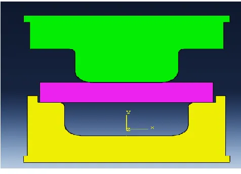
In this research; a rubber pad with dimensions of (75) mm in long and (5) mm thickness, with fillet radius (8) mm and (3) mm are used for analysis process as shown in Figure (1).
Fig. 1. Model geometry with diminutions in 2D and 3D form.
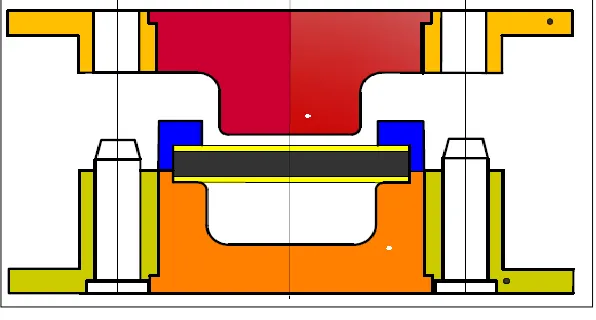
The manufacturing process tools are encompassing many parts; they are: insert, core lower plate, upper plate, guide, holder and rubber (90A). (CK45) steel with thickness (0.5) mm was placed above and under the rubber for enforcement purposes. Rubber hardness will in shore units. All tooling parts are illustrated in Figure (2) and Figure (3).
Fig. 2. 2D Mold assembly before action.
The tools consist of two pieces of steel with (206 GPa ) young modulus of elasticity, with (0.3) Poisson's ratio. Rubber (MAT 27) is used in this research, and the mechanical properties of rubber are listed in Table (1).Some boundary conditions must be taken in to consideration. So in terms of deformation and displacement; insert, blank holder and core are classified as rigid body, while the rubber is deformable. The process will start as the core move downward to be in touch with the rubber pad, and the process will end when the rubber pad formed to the final shape.
Table I
The Mechanical properties of rubber.
No.
Type
A
B
Density(kg/m
3)
Poisson’s Ratio
1
Shore 90
2.8
0.71
1.1x10
-90.5
Mathematically; it’s possible to define thestrainenergy density (€) by:- € = A (K1 -3) + B (K2 -3) +C (K23 -1) +D (K3 -1)2 (1) Where C = 0.5A+ B, K1, K2, K3 = invariants of right Cauchy Tensor C.
D= A (5 v -2) + B (K2 v -5) / 2(1- 2 v) (2) Where (v) is a Poisson’s ratio.
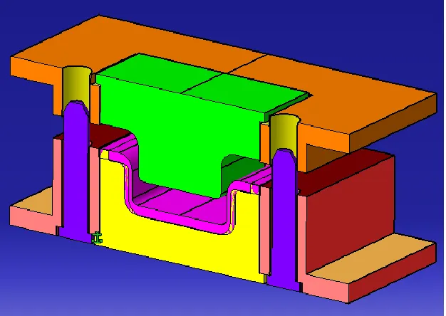
Modelling the assembly system before the simulation and experimental process will help for prevent any interference between the parts, decrease the error and time cost during simulation and will enhance the results. (CATIA V5 R16) are adopted for this process. Figure (4) and Figure (5) illustrating different steps in modelling process.
Fig. 5. Front sectional view of the 3D Model at the process end.
The key parameters include design parameters, design variable and the main functions. This process is involving analysis of the manufacturing process, topological distribution of the geometry and overall performance.
2- Finite Element Simulation Process
In this research; the finite element software (ABAQUS/CAE) has been adopted for analysis and simulation. In ABAQUS analysis; rubber material is modeld as fully deformable material (fully hyperplastic incompressible). That’s means all levels of strain is soft compared with steel material.
The initial step in simulation process is to make contact between rubbers and insert surfaces. The clearance between the core and insert will represent the product thickness (5) mm. Rubber material will be consider as an incompressible and hyperplastic which is very soft and have a high strain level.Figure (6) illustrate the contact between surfaces.
Fig. 6. Contact between surfaces.
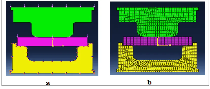
Fig. 7. (a) Load and boundary condition, (b) Parts mesh.
The behaviour of rubber during the forming process is consider as nonlinear elastic, and will describe by the nonlinear elastic function of strain energy, and this consider as a polynomial in second order for basic strain invariants. The analysis procedure of rubber pad is consider as multi steps in which the rigid body (Core) will move down toward rubber fold and distributes this material to the vicinity with clearance (5)mm (product thickness). These folds will fill the inside cavity between insert and core which form the rubber pad, as in Figure (8).
Fig. 8. First step of simulation while the core in contact with rubber.
Fig. 9. Second step of simulation while the core push the rubber downward
Fig. 10. Final step of simulation. Forming completed and the core move up.
The interaction and interference between the rubber material and the contact surfaces will be considered as glued with no required for any treatment.
In the final step of simulation shown in Figure (10);its appears that the geometry formation of the rubber pad is like folds of different surfaces will meet to contact itself and form a single surface.
Fig. 11. 4-node bilinear, hybrid withconstant pressure (CAX4H)
For this geometry, the analysis assumed and suggested that constrain must be imposed to the part thickness to form a connecting nodes along the curvature surface and fillet radius.
Changing and reducing the radius fillet with respect to the thickness and according to the nodal distribution will help to optimize the shape topology and yield the maximum axial stresses to the minimum values. The nonlinearity behaviour of these types of analysis can be referee to material properties under study as shown inFigure (12). The function of strain energy will be describing the behaviour of nonlinear elastic for rubber. During the strain invariants; this will consider as a second order polynomial quadrilaterals.
Fig. 12.Changing offillets with respect thickness.
The capability of self-contact in ABAQUS is available forlarge-slidingtwo-dimensional analysis. The components which can folds through forming process and substantially will change their shape according to some variables like pressure, surfaces alignment and temperature. This will help to control the orientation of the material to form optimal topology distribution and generate different surfaces in contact with each other’s.
3- EXPERIMENTAL SETUP
The experimental parts starting after assembling all the parts according to assembly design. Hydraulic press with adjustable stroke length and platforms dimension has been used according to the standard as shown in Figure (13).
The rubber folds distribution inside the insert with extra flash amount can be estimated and adjusted experimentally from the
beginning from few trials. . Shore scale is normally used for measuring rubber hardness. Samples used are normally (5) mm thickness with suitable area has
been selected. The test can be repeated for many samples to find the average values of hardness after forming process. 4- RESULTS AND DISCUSSION
The best method for numerically solving this type of nonlinear behaviour change and complex geometry, with many contact surfaces and material properties is by using Finite Element analysis.
Many of simulation parameters in this process are successfully modelled and determined during this finite element analysis.To establish a suitable correlation between shape design parameter and the analysis of design sensitivity, the option “parameter shape variation” specified with nodal coordinate’s gradients was applied during simulation process. These gradients can be simply obtained through changing the gradients of shape design (radius and thickness) with respect to specific time and record the coordinates as illustrated in Figure (14).
Fig. 14. Geometry nodal gradients distribution with respect to radius and thickness.
The high strain values which generated due the pressure will prevented or decreases by increasing the contact area between the rubber pad and insert surfaces.Strain values will reach the maximum values in the starting of forming process due to the high dislocation forcess of the particles especially between the adjacent surfaces near the pad holder. Contour graph in Figure (15) illiustate the herein above.
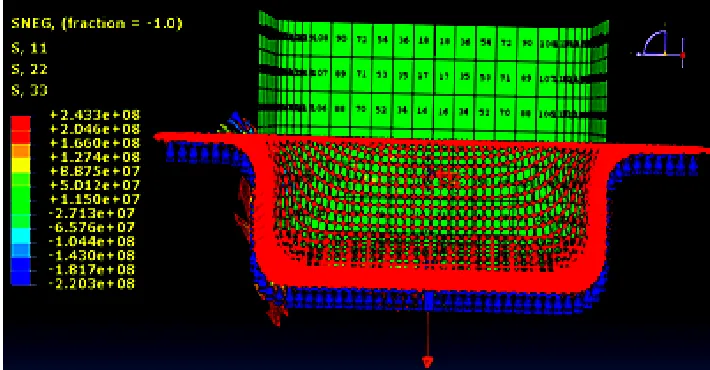
It has been found that effects of radius influence on stress generation is more than the effects of changing in rubber thickness, so in this case it’s desirable to be advise to change and increase the fillet radius than thickness to reduce the generation stresses. Axial stress contours for the deformed mesh at the end of axisymmetric analysis for rubber pad are shown in Figure (16).From this counter it’s very clear that the maximum stresses will occur near the fillet (radius) beside and alongside of all contact surfaces.
Fig. 16. Stress contour for the deformed mesh.
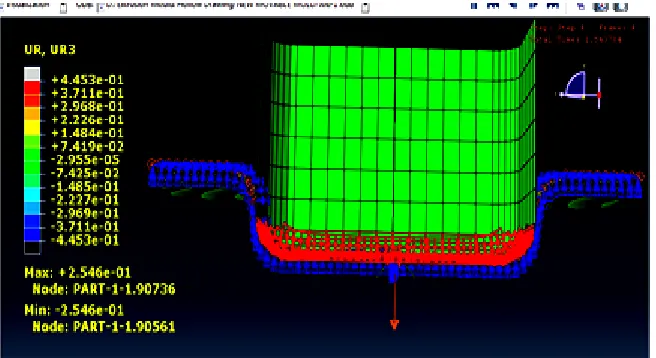
After upsetting and the core start rising up, and according to the variables of shape design, it’s found that, the axial stresses will be concentrate withmaximum values at the small fillets and large thickness values. Figure (17) shows the records of maximum and minimum stress values for some nodes.
Fig. 17. Contour of maximum and minimum stressconcentration for nodes.
Fig. 18. Pressure –Time relationship. Fig. 19. Displacement –Time relationship.
Comparison between the experimental results and simulation results revelled that there’s a good correlations between these results according to the strain – stress results as shown in Figure (20).Also in terms of compression ratio, the values of hardness test approved these results.
Fig. 20. Comparison between experimental and simulationresults.
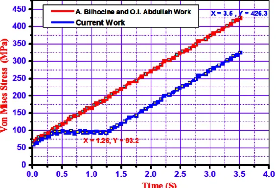
Fig. 21 Validation of present work in terms of Von-Mises Stresses.
5- CONCLUSIONS
Some conclusions can be listed from this study; they are:- -The work research discussed here is an import issue in
improving the manufacturing analysis of elastomer production. The first estimation from this analysis; its approved that (ABAQUS) is a powerful tools and good technique for analysis this type of manufacturing process. -Regarding to the material nature; there is an extensive contact
between the nodes, elements and surfaces. This helps in expanding the analysis and maximizes the output results during simulation.
-There are many goals have been achieved during the process; like load prediction and uniform geometry.The distribution of rubber folds inside the cavity with extra flash amount can be estimated from the beginning from few trials.
- According to this analysis, it’s found that, the main effecting parameters on the geometrical topology are the fillets zone and wall thickness.
- In this rubber model; the effects of large displacement, nonlinearities and large deformations on behaviour of material formation and distribution is very clear.
- Finite element simulation by (ABAQUS) enhance the results by modelling the actual process prior the experimental part and help to reduce the consuming time in design and test.In comparison purposes based on less costly time in test and redesign tools, and to reach the approach with completed results with respect of modelling the actual process; numerical analysis with (ABAQUS) which can match theories needs like stresses and strain changes. The reduction in cost and time is not less than (50) %.
- The ideal design parameters used with any model will enhance the results and performance by minimizing the cost, mass and volume of material.
REFERENCES
[1] L. Chen, H. Chen, Q. Wang, Z. Li, (2015). “Studies on wrinkling and control method in rubber forming using aluminium sheet shrink flanging process”. Materials and Design.65 505 - 510.
[2] A. del Prete, G. Papadia and B. Manisi, (2011). ‘Computer Aided Modelling of Rubber Pad Forming Process’. Key Engineering Materials. 473 637 - 644.
[3] OSCAR J. CENTENO G. (September 2009) . Finite Element Modeling of Rubber Bushing for Crash Simulation Experimental Tests and Validation. Master’s Dissertation. ISRN LUTVDG/TVSM--09/5163--SE (1-66) ISSN 0281-6679. [4] P. Pedersen. (Apr 2007). “On the Design of Compliant
Mechanisms Using Topology Optimization”. Mechanics of Structures and Machines. Volume 25, Pages 493-524.
[5] Austrell P.-E.,(2009). “Modeling of Elasticity and Damping for Filled Elastomers”, Report TVSM-1009, Lund University, Division of Structural Mechanics, Sweden.
[6] S. Caro, F. Bennis and P. Wenger. (2015). “Tolerance Synthesis of Mechanisms: A Robust Design Approach”. ASME Journal of Mechanical Design, 127 ,1, pp. 86–94.
[7] L. Chen, H. Chen, Q. Wang, Z. Li, (2015). “Studies on wrinkling and control method in rubber forming using aluminium sheet shrink flanging process”. Materials and Design.65 505 - 510. [8] D. B. Parkinson. (2000). “The application of a Robust Design
Method to Telebanking.”. ASME Journal of Mechanical Design. 122, pp 149–154.
[9] M.-S. Huang and T.-Y. Lin. Vergnano. (2008). “An innovative regression model-based searching method for setting the robust injection molding parameters”. Journal of Materials Processing Technology, 198, 3 , pp 436-444.
[10] S. Caro, F. Bennis and P. Wenger. (2015). “Tolerance Synthesis of Mechanisms: A Robust Design Approach”. ASME Journal of Mechanical Design, 127 ,1, pp. 86–94.
[11] Yu Wang, Jie Gao, Zhen Luo, Terry Brown & Nong Zhang. (Apr 2015). “Level-set topology optimization for multimaterial and multifunctional mechanical metamaterials”. The University of Technology, Sydney, NSW, Australia. Journal Engineering Optimization. Volume 49, Issue 1. Pages 22-42.
[12] Ren-Jye Yang &Kyung K. Choi. (Mar 2007). “Accuracy of Finite Element Based Shape Design Sensitivity Analysis”. Journal of Structural Mechanics. Volume 13, Issue 2- Pages 223-239. [13] A.O. Andrisano, M. Ansaloni, F. Leali, M. Pellicciari, A.
Vergnano. (2011). “A novel method for sensitivity analysis and characterization in integrated engineering design”. Department of Mechanical and Civil Engineering – University of Modena and Reggio Emilia (Italy). Proceedings of the IMProVe. Volume 13, Issue 2- Pages 223-239