DOA ESTIMATION & BEAM FORMING USING AD8302
Kuldeep B. Miraje1 &Dr. Uttam L. Bombale
21.INTRODUCTION
In the last decade's direction of arrival estimation and beam forming methods are evolving in large scale. These methods have wide scope and applications in communication, navigation, SONAR, RADAR, RADAR jammer and other military application. There are various methods adopted for direction finding depending on accuracy and complexity challenging task is to select the appropriate method for particular application.
Use of communication technology is growing at a faster rate over the years. There are various techniques developed to enhance the demand for higher data rate and more number of users per channel. Communication technology emerges from the first generation to the fourth generation in early days. The need for increased data rate and more number of subscribers per channel is also a challenging task for various service providers. Hence the use of direction detection and beam forming techniques is the early need. Direction detection technology determines the position of a subscriber and transmits signals to that particular direction only. Due to this technology, there is increased security and signal strength at receiving side.
Smart antenna is the main concern of this DOA estimation phenomenon, where smart antenna (also known as adaptive array antennas, multiple antennas and, recently, MIMO) is nothing but "smart antenna is nothing but antenna with its ability to perform signal processing for finding direction of transmitting antenna by the use of amplitude/phase/time difference of arrival or for beam forming, to survive in rescue operation or mobile tracking". Beam forming is the "method for adopting radiation pattern of the antennas in particular direction and nulling pattern in other direction by constructively change phase/time of signals to be transmitted. that increases signal strength in particular direction and reduce noise" The smart antenna system estimates the direction of arrival of the signal, using techniques such as MUSIC (MUltiple SIgnal Classification)[1,2], estimation of signal parameters via rotational invariance techniques (ESPRIT)[1] algorithms, Matrix Pencil method or one of their derivatives. They involve finding a spatial spectrum of the antenna/sensor array and calculating the DOA from the peaks of this spectrum. These calculations are computationally intensive. Matrix Pencil is very efficient in case of real time systems and under the correlated sources.
Use of signal processing circuitries like FPGA [2], DSP [4], SDR [5], and DAQ [6] are common methods for direction detection. These components are used in signal processing purpose for finding phase/amplitude/frequency difference of receiving antenna signal. These circuitries take antenna input calculate phase/amplitude difference between those antenna signals and determines the exact direction of arrival of the signal. Use of these circuitries in a circuit is much bulky and costly. To avoid this in the proposed system phase detector circuitry is used which is nothing but AD8302 [7] chip. This phase detector is very low cost and more reliable than other circuitries.
The AD8302 is a fully integrated system for measuring gain/loss and phase in numerous receive, transmit, and instrumentation applications. It requires few external components and a single supply of 2.7 V–5.5 V. The AC-coupled input signals can range from –60 dBm to 0 dBm in a 50 Ω system, from low frequencies up to 2.7 GHz. The outputs provide an accurate measurement of either gain or loss over a ±30 dB range scaled to 30 mV/dB and of phase over a 0°–180° range scaled to 10 mV/degree. Both subsystems have an output bandwidth of 30 MHz, which may optionally be reduced by the addition of external filter
1 M. Tech. Student, Department of Electronics Technology, Department of Technology Shivaji University, Kolhapur (416004)
Maharashtra, India
2 Associate Professor, Department of Electronics Technology. Department of Technology Shivaji University, Kolhapur
(416004) Maharashtra, India
International Journal of Latest Trends in Engineering and Technology
Vol.(9)Issue(1), pp.207-212
DOI: http://dx.doi.org/10.21172/1.91.31
e-ISSN:2278-621X
Abstract - Adaptive antenna is emerging area in telecommunication industries which has ever-growing scope and application in RADAR as well as communication industry. Nowadays DOA estimation and beam forming are wildly used in RADAR and 4G/5G technology. In this paper, we proposed a system which will determine the direction of transmitting antenna (DOA estimation) using phase detector and transmit signal in that direction (beam forming). This process makes antenna more directives and increases the efficiency. In the proposed system one transmitting antenna is transmitting at frequency 2.4-2.5 GHz from a certain angle. There are two receiving antennas which receive signals but there is some phase/time/amplitude difference between those two antenna signals. From that phase/time/amplitude difference, the exact angle of arrival of signals is calculated. After determining the angle of arrival using VCO, power divider and phase shifter the direction of transition of antenna signal is changed this method is called beamforming. Use of the phase detector circuit reduces complexity and need of use of complex algorithms like MUSIC, ESPRIT etc., this also reduces overall cost.
capacitors. The AD8302 can be used in controller mode to force the gain and phase of a signal chain toward predetermined set points.
For connecting phase detector circuit in the proposed system, we have used Arduino Uno. The Arduino Uno is a microcontroller board based on the ATmega328. It has 14 digital input/output pins (of which 6 can be used as PWM outputs), 6 analog inputs, a 16 MHz crystal oscillator, a USB connection, a power jack, an ICSP header, and a reset button. It contains everything needed to support the microcontroller; simply connect it to a computer with a USB cable or power it with an AC-to-DC adapter or battery to get started. The Uno differs from all preceding boards in that it does not use the FTDI USB-to-serial driver chip. Instead, it features the Atmega8U2 programmed as a USB-to-USB-to-serial converter.
This paper discusses proposed system in section II, whereas in section III results are given. Section IV gives overall conclusion and Section V given all the references referred while studying.
2.PROPOSEDSYSTEM
There are various components are used in DOA estimation and beam forming process which are work together in a relation to perform desired task.
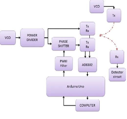
Figure 1. Hardware Block Diagram
2.1 Direction Detection
As shown in above fig in first part direction of transmitting antenna is determined. There are two receiving antennas are placed half wavelength apart from each other. This transmitting antenna transmits a signal at a certain angle from receiving antennas. Those two receiving antenna receive signal, due to transmitter is transmitting at some degree from center location the transmitted signal can reach receiving antenna at different time. The nearest antenna can receive signal early Also there is some phase or amplitude difference between those two receiving antenna signals. From that phase/time/amplitude difference, we have to calculate the exact angle of radiation of signal. Phase detector AD8302 is a phase difference calculating IC which can calculate phase difference up to 1800 and give output voltage in range of 0 to 1.8V from this voltage we can calculate the exact angle of arrival of signal. AD8302 had Accurate Phase Measurement Scaling (10 mV/Degree). Also, there are other methods by the use of time difference or amplitude difference of arrival of signal but are not much effective and practical.
VOUT =VSlope log (VIn /Vx) (1)
Where,
VIn - Input Voltage
Vx - Intercept Voltage
VSlope - Slope Voltage
VMagnitude =VSlope log (VIn-A /VIn-B) (2)
Where,
VIn-A and VIn-B - Input Voltages
VMagnitude - Magnitude Difference Voltage
Where,
VPhase - Phase Difference Voltage
Figure 2. Graph of Phase Difference V/S Output Voltage
The voltage output of phase detector is given to ADC to transmit serially to computer for that purpose Arduino Uno kit is used which has in built ADC and DAC (PWM). It has 14 digital input/output pins (of which 6 can be used as PWM outputs), 6 analog inputs. By the use of voltage output from AD8302 Arduino can calculate the exact angle of arrival this data is then transmitted to the computer serially. In computer GUI of angle of arrival, detection is visualized by using windows form application in visual studio by the use of meter gauge dynamic link library.
2.2 Beam Forming
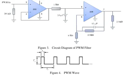
From the first part, we can calculate the exact angle of arrival of signal so in second part we work on beam forming process. Now take a look at circuit diagram one VCO is connected which is 0 to 2.7GHz voltage controlled oscillator. This oscillator can generate signal of 2.4 GHz using tuning voltage 3V. This VCO signal is then transmitted to the power divider circuit. This power divider can divide this signal into two equal signals. As we know Beam forming is the method used to create the radiation pattern of the antenna array by adding constructively the phases of the signals in the direction of the targets/mobiles desired and nulling the pattern of the targets/mobiles that are undesired/interfering targets. For that purpose, we need to change phase of one of the two power divider outputs using phase shifter. Power divider had two outputs one is directly fed to the antenna and another is given to the phase shifter circuit which is controlled by biasing/tuning voltage. The biasing signal is given from Arduino Uno. DAC converter (PWM) is used to tune the phase shifter. This signal can change the phase of the output of phase shifter signal. In correlation with that, the signal can be changed and direction of radiation of signal is changed.
Figure 3. Circuit Diagram of PWM Filter
Where,
Vs=5V
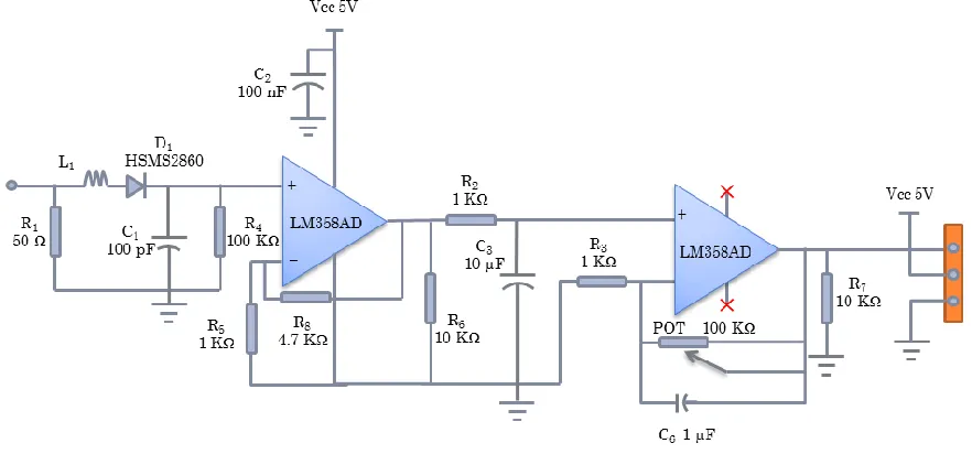
As shown in above fig PWM signals are converted into analog signal using this PWM filter. For ensuring the results of beam forming method detector circuit is used. As antenna signals received by beam forming are very small in magnitude. This circuit can convert antenna received signals into voltage output and amplify those small voltage values, to determine signal strength at various angles.
Figure 5. Circuit Diagram of Detector Circuit
3.RESULT
By the use of above method, we calculated result as shown in following. Where direction of arrival is shown using GUI on computer and beam forming results are measured using voltage measuring instrument.
Figure 6. Resulted GUI on computer for visualize angle of arrival of signal for that we get 1.80 V at detector output
Angle of arrival Voltage received at phase detector output in volts
Angle of arrival Voltage received at phase detector output in volts
000 0.90 1000 1.70
100 1.00 1100 1.60
200 1.10 1200 1.50
300 1.20 1300 1.40
400 1.30 140 1.30
500 1.40 150 1.20
600 1.50 160 1.10
800 1.70 180 0.90
900 1.80
Table 1: Resulted voltages at detector output on different angles
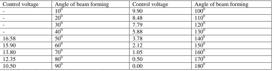
Following result are obtained after beam forming as we change tuning voltage of phase shifter angle of beams forming also changes. The control voltage of phase shifter is from 0 to 15 volts.
Control voltage Angle of beam forming Control voltage Angle of beam forming
- 100 9.90 1000
- 200 8.48 1100
- 300 7.79 1200
- 400 5.88 1300
16.58 500 3.78 1400
15.90 600 2.12 1500
13.80 700 1.05 1600
12.35 800 0.50 1700
10.50 900 0.00 1800
Table 2: Resulted angle as varying control voltage
4.CONCLUSIONS
This paper gives overview of various DOA estimation techniques along with their advantages and flows in DOA estimation process. From that, it concludes that music and sprite are two best suitable methods for DOA estimation. There are various parameters which can cause in change of accuracy as well as bandwidth like no of snapshot, no of transmitted signals, distance between two antennas etc. there are various signal processing circuitries are used for direction finding. Use of FPGA, DAQ, DSP, SDR and other methods increase complexity of circuitry. Newly adopted phase detector circuit is more reliable than other circuitries as they are cheap and easy to handle. In the proposed work we had used AD8302 phase detector which gives best result. Due to use of phase detector circuit, the cost is reduced by a scale factor of 97% along with reduction in complexity.
5.REFERENCES
[1] Moustafa M. Abdalla Electronic Engineering Dept. Engineering Academy Tajoura – Libya Mostafa B. Abuitbel Electronic Engineering Dept. Engineering Academy Tajoura – Libya Mohamed A. Hassan Electrical Engineering Dept. Azzaytuna University Tarhona – Libya “Performance Evaluation of Direction of Arrival Estimation Using MUSIC and ESPRIT Algorithms for Mobile Communication Systems” 978-1-4673-5616-9/13/$31.00 ©2013 IEEE.
[2] Mikel Arenas, Adam Podhorski, Saioa Arrizabalaga, Jon Goya, Beatriz Sedano, Jaizki Mendizabal CEIT and Tecnun (University of Navarra) Manuel de Lardizábal 15, 20018 San Sebastián. “Implementation and validation of an Angle of Arrival (AOA) determination system” 978-1-4673-7228-2/15/$31.00 ©2015 IEEE.
[3] Yang Bina , He Fenga , Jin Jinb , Xiong Huaganga , Xu Guanghana, “DOA estimation for attitude determination on communication satellites” Received 13 May 2013; revised 4 November 2013; accepted 10 December 2013.
[4] Ying Liua, Hongyuan Cuia aUniversity of Chinese Academy of Sciences, Beijing, 100190, China “Antenna Array Signal Direction of Arrival Estimation on Digital Signal Processor (DSP)” Procedia Computer Science 55 ( 2015 ) 782 – 791 1877-0509 © 2015 Published by Elsevier B.V. Information Technology and Quantitative Management (ITQM 2015)1877-0509 © 2015 Published by Elsevier B.V.
[5] Hsieh-Chung Chen, Tsung-Han Lin, H. T. Kung, Chit-Kwan Lin, Youngjune Gwon School of Engineering and Applied Sciences Harvard University “Determining RF Angle of Arrival Using COTS Antenna Arrays: A Field Evaluation”.
[6] Raed M. Shubair, Mahmoud A. Al-Qutayri, and Jassim M. Samhan Etisalat University College “A Setup for the Evaluation of MUSIC and LMS Algorithms for a Smart Antenna System” Journal Of Communications, Vol. 2, No. 4, June 2007.
[7] Tyler Chun, University Of Hawaii Patent Citation Publication number WO2012161883 A2 Application number PCT/US2012/033385 “Autonomous multiple-interrogator RF-jammer WO 2012161883 A2” Publication date Nov 29, 2012.
[8] Janis Werner, Student Member, IEEE, Jun Wang, Aki Hakkarainen, Student Member, IEEE, Nikhil Gulati, Member, IEEE, Damiano Patron, Student Member, IEEE, Doug Pfeil, Kapil Dandekar, Senior Member, IEEE, Danijela Cabric, Member, IEEE, and Mikko Valkama, Member, IEEE “Sectorized Antenna-based DOA Estimation and Localization: Advanced Algorithms and Measurements” 10.1109/JSAC.2015.2430292, IEEE Journal on Selected Areas in Communications, 0733-8716 (c) 2015 IEEE.
[9] S. Sana, Sahil Waqar, H. Yusaf, M. Waqas and Fayyaz A. Siddiqui Centre of Excellence in Science and Applied Technology (CESAT), Islamabad, Pakistan “Software Defined Digital Beam Forming Processor” copyright 2016 IEEE.
[10] Ali Gorcin and Huseyin Arslan “A Two-Antenna Single RF Front-End DOA Estimation System for Wireless Communications Signals.” IEEE Transactions on Antennas and Propagation, Vol. 62, No. 10, October 2014.
[11] Pooja Gupta, S.P. Kar “Music and Improved Music Algorithm to Estimate Direction of Arrival” This full-text paper was peer-reviewed and accepted to be presented at the IEEE ICCSP 2015 conference.
Step-Size Of Least Mean Squares Filter In The Accuracy Of Extraction Of Passive RFID Root Music Direction-Of arrival Estimates” Philippine Section 12-16 November 2013 Hotel Centro, Puerto Princesa, Palawan, Philippines ©2013 IEEE.
[14] Marshall Grice', Jeff Rodenkirch', Anatoly Yakovlev', H. K. Hwang', Zekeriya Aliyazicioglu', Anne Lee2 'California State Polytechnic University, Pomona, Electrical and Computer Engineering, gricegdcsupomona.edu, jirodenkirchdgcsupomona. edu, aayakov1ecvgdcsupomona.edu, h1,dihwang csuipomona.ed., zaliy_zicigcsupomona.edu Pomona, California 91768, USA 2Raytheon Company, Ann L_Lee n.com El Segundo, CA, USA “Direction Of Arrival Estimation Using Advanced Signal Processing” 1-4244-1057-6/07/$25.OO ©)2007 IEEE.
[15] Kyungjung Kim, Tapan K. Sarkar, Fellow, IEEE, Hong Wang, and Magdalena Salazar-Palma, Senior Member, IEEE “Direction Of Arrival Estimation Based On Temporal And Spatial Processing Using A Direct Data Domain (D3) Approach” IEEE Transactions On Antennas And Propagation, Vol. 52, No. 2, February 2004.