Architectures & Applications
Brasser, Franz Ferdinand Peter(2020)
DOI (TUprints): https://doi.org/10.25534/tuprints-00011912
Lizenz:
CC-BY-NC-ND 4.0 International - Creative Commons, Namensnennung, nicht kom-merziell, keine Bearbeitung
Publikationstyp: Dissertation
Fachbereich: 20 Fachbereich Informatik
H
-
S
A
& A
p p l i c a t i o n s
Vom Fachbereich Informatik (FB20)
an der Technischen Universität Darmstadt
zur Erlangung des akademischen Grades eines Doktor-Ingenieurs genehmigte Dissertation von:
MSc. Franz Ferdinand Peter Brasser
Geboren am27. April1984in Wolfenbüttel, Deutschland
Referenten:
Prof. Dr.-Ing. Ahmad-Reza Sadeghi (Erstreferent) Prof. Gene Tsudik, PhD (Zweitreferent)
Tag der Einreichung:06. April2020
Tag der Disputation:23. Juni 2020
System Security Lab Fachbereich für Informatik Technische Universität Darmstadt
Enclave Computing Paradigm: Hardware-assisted Security Architectures & Applications © April2020
p h d r e f e r e e s:
Prof. Dr.-Ing. Ahmad-Reza Sadeghi (1st PhD Referee) Prof. Gene Tsudik, PhD (2nd PhD Referee)
Darmstadt, Germany April2020
Veröffentlichung unter CC-BY-NC-ND4.0International Namensnennung, nicht kommerziell, keine Bearbeitung
Hardware-assisted security solutions, and the isolation guarantees they provide, consti-tute the basis for the protection of modern software systems. Hardware-enforced isolation of individual components reduces complexity of the overall software as well as the size and complexity of the individual components. The basic idea is that a reduction in com-plexity minimizes the probability of vulnerabilities in the software, thus strengthening the system’s security.
In classical system architectures, an application’s security depends on the security of all privileged system entities, for example the Operating System. The Trusted Execution Environment (TEE) concept overcomes the dependence of security critical components on the systems overall security.TEEs provide isolated compartments within a single system, allowing isolated operation of a system’s individual components and applications.
Theenclave computing paradigmenhances theTEEconcept by enabling self-contained isolation of system components and applications, fulfilling the needs of modern software. It enables novel use cases by providing many parallel mutually isolatedTEE-instances without the need to rely on complex privileged entities.
The TEE solutions developed by industry and deployed in today’s systems follow distinct design approaches and come with various limitations. ARM TrustZone, which is widely available in mobile devices, is fundamentally limited to a single isolation domain. Intel’sTEEsolution Software Guard Extensions (SGX) provides multiple mutually iso-lated execution environments, calledenclaves. However,SGXenclaves face severe threats, in particular channel leakage, that can void its security guarantees. Preventing side-channel leakage from enclaves in a universal and efficient way is a non-trivial problem. Nevertheless, these deployedTEEsolutions enable various novel applications. However, differentTEEarchitectures come with diverse properties and features that require special consideration in the design ofTEEapplications.
Security architectures for embedded systems face additional challenges that have not been solved, neither by industry nor by academic research. These security architectures need to be compliant with and need to preserve all functional requirements of an embedded system. Since network-connected embedded devices are increasingly used in safety critical systems, such as industrial control systems or automotive scenarios, security architectures that combine safety and security aspects are vitally needed.
Remote Attestation (RA) is a security service that relies on the isolation guarantees ofTEEs. It is of particularly high relevance for connected embedded systems. It allows trust establishment between these devices enabling their reliable collaboration in large connected systems. However, many aspects ofRA, such as its scalability in large networks or its applicability in autonomous connected systems, are unexplored.
In this dissertation, we present novel isolation architectures that bring the enclave computing paradigm to mobile and embedded platforms. We present the first security
real-time guarantees. Moreover, we present a novel multi-TEE security architecture for TrustZone-systems bringing the enclave computing paradigm to mobile systems, overcoming TrustZone’s fundamental limitation.
Furthermore, we deal with IntelSGX’s vulnerability to side-channel attacks. We demon-strate the severity of side-channel leakage due to observable memory access patterns of SGXenclaves. To counter side-channel attacks, we present solutions that hide memory access patterns of enclaves for both accesses to enclave-external memory as well as access patterns within enclaves’ private memory.
We present twoTEE-applications that follow different design approaches, leveraging the specific capabilities of IntelSGXand ARM TrustZone, respectively. We introduce a cloud-based machine learning solution that enables privacy-preserving speech recog-nition utilizing isolated execution enclaves. We also demonstrate the limitations of the enclave computing paradigm and show a (remote) policy enforcement solution for mobile devices, which requires an isolated execution environment with elevated privileges.
Additionally, we investigate novelRAschemes, which tackle many important aspects ofRAthat are highly relevant in emerging connected systems. We develop solutions to prevent the misuse of remote attestation for Denial-of-Service (DoS) attacks and present the first efficient multi-prover attestation scheme. Furthermore, we introduce the concept of data integrity attestation, which allows the efficient and reliable collaboration of autonomous connected devices.
Hardware-basierte Sicherheitslösungen und die durch sie gebotenen Sicherheitsgarantien bilden die Basis zum Schutz moderner Softwaresysteme. Durch die Isolation von Sys-temkomponenten durch Hardwaremechanismen können die Größe und Komplexität des Gesamtsystems als auch der individuellen Komponenten reduziert werden. Somit sorgt Isolation für eine Verbesserung der Systemsicherheit, denn eine Reduktion der Komplexität führt in der Regel gleichzeitig zu einer Reduktion der Wahrscheinlichkeiten von Schwachstellen in der Software.
In herkömmlichen Computerarchitekturen hängt die Sicherheit einer Anwendung von der Sicherheit aller privilegierten Systemkomponenten, wie etwa dem Betriebssys-tem, ab. Das Konzept von Trusted Execution Environments (TEEs) überwindet diese Abhängigkeit, d.h. sicherheitskritische Systemkomponenten sind nicht mehr von der Sicherheit des Gesamtsystems abhängig.TEEs stellen isolierte Bereiche innerhalb eines einzelnen Systems bereit, diese erlauben die abgeschottete Ausführung der individuellen Komponenten eines Systems.
Das Enclave Computing Paradigma entwickelt das TEE Konzept weiter und bietet in sich geschlossene Isolationsbereiche für Systemkomponenten und Anwendungen. Somit erfüllt es die Anforderungen moderner Software. Es ermöglicht neuartige Anwendungs-fälle, da viele parallele, wechselseitig isolierteTEE-Instanzen geschaffen werden, ohne auf komplexe privilegierte Komponenten angewiesen zu sein.
Die durch die Industrie entwickelten und aktuell verfügbarenTEE-Lösungen folgen unterschiedlichen Ansätzen und leiden unter verschiedenen Nachteilen. ARM TrustZone, das in vielen mobilen Systemen integriert ist, hat die zentrale Einschränkun, dass es nur eine einzige Isolationsdomäne bietet. Intel Software Guard Extensions (SGX) bietet hinge-gen viele, wechselseitig isolierte Ausführungsumgebunhinge-gen, dieEncalvesgenannt werden. Allerdings werden SGX-Enclaves von schwerwiegenden Schwachstellen bedroht, die ihre Sicherheitsgarantien zunichtemachen können. Vor allem Angriffe, die Seitenkanäle ausnutzen, bedrohen SGX. Eine generelle und effiziente Lösung zu finden, die Seit-enkanalangriffe auf Enclaves verhindern kann, stellt dabei ein nicht-triviales Problem dar. Trotz ihrer Probleme ermöglichen diese bereits verfügbarenTEE-Lösungen viele neue An-wendungen. Bei der Konzeptionierung und Entwicklung vonTEE-Anwendungen müssen allerdings die spezifischen Eigenschaften der jeweiligenTEE-Architekturen berücksichtigt werden.
Bei Sicherheitsarchitekturen für eingebettete Systeme ergeben sich zusätzliche Her-ausforderungen, die überwunden werden müssen. Dies ist bislang weder der Industrie noch der akademischen Forschung gelungen, da diese Sicherheitsarchitekturen die funk-tionalen Eigenschaften des zugrundeliegenden Systems erhalten müssen. Vernetzte eingebettete System werden zunehmend in sicherheitskritischen Bereichen, etwa in der Industrieautomatisierung oder in der Fahrzeugsteuerung, eingesetzt. Deshalb sind hier
von entscheidender Bedeutung.
Remote Attestation (RA) ist ein Sicherheitsmechanismus, der auf den Isolations-garantien vonTEEs aufbaut.RAist besonders wichtig im Kontext vernetzter eingebetteter Systeme. Es erlaubt den Aufbau von Vertrauensverhältnissen zwischen Systemen und ermöglicht so die verlässliche Kollaboration dieser in weitvernetzten Anlagen. Allerdings sind viele Aspekte vonRA, etwa zur Skalierbarkeit in großflächigen Netzwerken oder zur Anwendbarkeit in autonomen Systemen, noch unerforscht.
In dieser Dissertation stellen wir neue Isolationsarchitekturen vor, die das Enclave-Konzept für Mobilsysteme und eingebettete Systeme umsetzen. Wir präsentieren die erste Sicherheitsarchitektur für kleine eingebettete Systeme, die isolierte Ausführungsumge-bungen ermöglicht und gleichzeitig Echtzeitgarantien bietet. Für mobile Systeme präsen-tieren wir eine neuartige Sicherheitsarchitektur, die viele unabhängigeTEE-Instanzen auf TrustZone-basierten Systemen ermöglicht, und somit die zentrale Einschränkung von TrustZone überwindet.
Weiterhin betrachten wir die Verwundbarkeit von IntelSGXdurch Seitenkanalangriffe. Wie demonstrieren die Ernsthaftigkeit von Angriffen, welche die Speicherzugriffsmuster einerSGX-Enclave überwachen. Zur Abwehr von Seitenkanalangriffen präsentieren wir Lösungen, die sowohl den Zugriff einer Enclave auf externen Speicher wie auch die Zugriffsmuster im Enclave-eigenen Speicher verbergen.
Wie präsentieren zweiTEE-Anwendungen, die unterschiedlichen Konzepten folgen, dabei nutzen sie die spezifischen Möglichkeiten von IntelSGX bzw. ARM TrustZone. Wir stellen eine Cloud-basierte Lösung für maschinelles Lernen vor, die Privatsphäre-schützende Spracherkennung durch die Nutzung von Enclaves ermöglicht. Zudem zeigen wir die Grenzen des Enclave Computing Paradigmas anhand einer Lösung auf, die ortsabhängige Nutzungsregeln für Mobilgeräte durchsetzen kann, welche jedoch nur mit einer isolierten Ausführungsumgebung mit erhöhten Privilegien umsetzbar ist.
Darüber hinaus entwickeln wir neue RA Mechanismen, die wichtige Aspekte be-trachten, die vor allem im Kontext von künftigen vernetzten Systemen hohe Relevanz haben. Wir entwickeln Lösungen, die den Missbrauch von Remote Attestation für Dienst-verweigerungsattacken (Denial-of-Service) verhindern, und wir präsentieren das erste Protokoll zur effizienten gleichzeitigen Attestierung vieler Geräte. Weiterhin führen wir das Konzept der Datenintegritätsattestierung ein, welches die verlässliche und effiziente Kollaboration von autonom interagierenden Geräten ermöglicht.
First and foremost, I would like to thank my advisor Prof. Ahmad-Reza Sadeghi for his guidance and support during my doctorate. His dedication to research has inspired me already during my master studies and encouraged me to pursue a PhD. He supported my research in various ways, most importantly, he gave me the freedom to follow my own research ideas, he connected me with many well established researchers worldwide, and he made me a part of his System Security Lab for almost a decade – first as a student assistant and later as a research assistant.
I am very honored to have Prof. Gene Tsudik as my thesis co-advisor and would like to thank him for his detailed feedback on this thesis as well as for the inspiring discussions in the course of our collaborations.
During my time at the System Security Lab I had the opportunity and pleasure to have worked together with many professors, colleagues, and students. I had many interesting projects with them and I want to thank everyone for their contribution to the success of these collaborations. My thanks go to the external collaborates from academia and industry as well as to my colleagues and students at TU Darmstadt. I want to express my thanks to the team members of the System Security Lab that were always supportive and contributed to a pleasant work atmosphere.
Finally, I would like to thank my family and friends for their support before and during my doctorate. Special thanks go to my parents. They always supported me and believed in me. Thanks to them I was able to study, even after some throwbacks. Without their encouragement I could not have made it.
1 i n t r o d u c t i o n 1
1.1 Contributions . . . 3
1.2 Previous Publications . . . 4
2 p r e l i m i na r i e s a n d b a c k g r o u n d 7 2.1 Computer Architectures . . . 7
2.1.1 Memory Management and Memory Protection . . . 8
2.1.2 Cache Architectures . . . 11
2.2 Security Services . . . 14
2.2.1 Secure Boot . . . 14
2.2.2 Attestation . . . 18
2.3 Security Architectures and TEEs . . . 20
2.3.1 ARM TrustZone . . . 20
2.3.2 Intel Software Guard Extensions . . . 23
2.4 Background on Side-Channel Attacks . . . 25
2.4.1 Controlled-Channel Attacks . . . 25
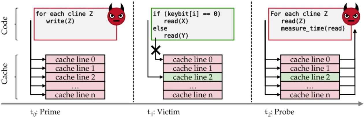
2.4.2 Cache Side-Channel Attacks . . . 26
3 s e c u r i t y a r c h i t e c t u r e s 29 3.1 TyTA N: Tiny Trust Anchor for Tiny Devices . . . 30
3.1.1 Requirements . . . 31
3.1.2 System and Trust Model . . . 32
3.1.3 TyTA N Design . . . 34
3.1.4 Implementation . . . 39
3.1.5 Security Analysis . . . 46
3.1.6 Evaluation . . . 47
3.1.7 Conclusion . . . 52
3.2 Sa n c t ua r y: ARMing TrustZone with User-space Enclaves . . . 53
3.2.1 Background . . . 54
3.2.2 Adversary Model and Requirements . . . 55
3.2.3 Sa n c t ua r y Design . . . 56 3.2.4 Implementation . . . 60 3.2.5 Security Analysis . . . 60 3.2.6 Evaluation . . . 63 3.2.7 Conclusion . . . 64 3.3 Related Work . . . 65 3.3.1 Virtual-Memory-based Systems . . . 66 3.3.2 Physical-Memory-based Systems . . . 68 4 t e e at ta c k s a n d d e f e n s e s 71 4.1 Software Grand Exposure . . . 72
4.1.1 Background . . . 73
4.1.2 System and Adversary Model . . . 73
4.1.3 Our Attack Design . . . 75
4.1.4 Attack Instantiations . . . 78
4.1.5 Conclusion . . . 85
4.2 HardIDX . . . 86
4.2.1 Background . . . 87
4.2.2 Model and Assumptions . . . 88
4.2.3 HardIDX Design . . . 89
4.2.4 Search Algorithms . . . 90
4.2.5 Performance Evaluation . . . 92
4.2.6 Conclusion . . . 93
4.3 DR.SGX . . . 94
4.3.1 Model and Assumptions . . . 95
4.3.2 DR.SGX Concept and Design . . . 97
4.3.3 DR.SGX Implementation . . . 102 4.3.4 Performance Evaluation . . . 104 4.3.5 Security Analysis . . . 104 4.3.6 Conclusion . . . 106 4.4 Related Work . . . 107 4.4.1 Side-Channel Attacks . . . 107 4.4.2 Side-Channel Countermeasures . . . 111 5 t e e a p p l i c at i o n s 117 5.1 VoiceGuard . . . 118
5.1.1 Model and Assumptions . . . 119
5.1.2 VoiceGuard Design . . . 119
5.1.3 Implementation and Evaluation . . . 122
5.1.4 Conclusion . . . 123
5.2 Regulating ARM TrustZone Devices in Restricted Spaces . . . 124
5.2.1 System Model, Assumptions and Requirements . . . 125
5.2.2 Design . . . 127
5.2.3 Implementation and Evaluation . . . 130
5.2.4 Conclusion . . . 131
5.3 Related Work . . . 132
5.3.1 Privacy-preserving Machine Learning . . . 132
5.3.2 Mobile Device Management . . . 133
5.3.3 (Remote) Memory Operations . . . 134
5.3.4 Trusted Execution Environment (TEE) Applications . . . 135
6 s e c u r i t y s e r v i c e: r e m o t e at t e s tat i o n 137 6.1 Prover’s Perspective on Remote Attestation . . . 138
6.1.1 System and Adversary Model . . . 138
6.1.2 Mitigating Advext . . . 141
6.1.3 Mitigating Advroam . . . 143
6.1.4 Implementation . . . 144
6.1.6 Conclusion . . . 148
6.2 SEDA: Scalable Embedded Device Attestation . . . 149
6.2.1 System Model and Preliminaries . . . 149
6.2.2 SEDA Protocol . . . 151
6.2.3 Prototype and Implementation . . . 155
6.2.4 Performance Evaluation . . . 157
6.2.5 Security Analysis . . . 159
6.2.6 Protocol Extensions . . . 161
6.2.7 Physical Attacks . . . 163
6.2.8 Conclusion . . . 165
6.3 DIAT: Data Integrity Attestation . . . 166
6.3.1 Model and Assumptions . . . 167
6.3.2 DIAT Design . . . 172 6.3.3 Implementation . . . 176 6.3.4 Performance Evaluation . . . 176 6.3.5 Security Analysis . . . 177 6.3.6 Discussion . . . 179 6.3.7 Conclusion . . . 181 6.4 Related Work . . . 182 6.4.1 Attestation . . . 182 6.4.2 Integrity Enforcement . . . 189 7 d i s c u s s i o n a n d c o n c l u s i o n 191 7.1 Summary of Dissertation . . . 191
7.2 Future Research Directions . . . 192
8 a b o u t t h e au t h o r 195
b i b l i o g r a p h y 201
Table1 TyTA N use-case evaluation results . . . 49
Table2 TyTA N’s secure task context saving performance . . . 49
Table3 TyTA N’s secure task context restoring performance . . . 49
Table4 TyTA N’s task relocation performance . . . 49
Table5 TyTA N secure task creation performance . . . 49
Table6 TyTA N’sEA-MPUconfiguration performance . . . 50
Table7 TyTA N’s task measurement performance . . . 50
Table8 TyTA N OS memory cost . . . 51
Table9 TyTA N LoC . . . 52
Table10 Siskiyou Peak cryptographic primitives performance . . . 140
Table11 Summary of Denial-of-Service (DoS) attack mitigation features. . 143
Table12 TyTA N components hardware cost . . . 148
L I S T O F F I G U R E S
Figure1 Hierarchical computer architectures . . . 8Figure2 Memory Management Unit (MMU) . . . 9
Figure3 Memory Protection Unit (MPU) . . . 11
Figure4 Execution-Aware Memory Protection Unit (EA-MPU) . . . 12
Figure5 Central Processing Unit (CPU) caches mappings . . . 13
Figure6 Cache hierarchy and addressing . . . 14
Figure7 Chain of Trust (CoT) Concept . . . 14
Figure8 Chain of Trust (CoT): validation and execution order . . . 15
Figure9 Secure boot with embeddedIMVs . . . 16
Figure10 Secure boot with centralIMVs storage . . . 17
Figure11 Secure boot withIMVcertificates . . . 17
Figure12 TrustZone software and hardware components . . . 21
Figure13 Prime+Probe side-channel attack . . . 26
Figure14 TyTA N trust relations . . . 33
Figure15 TyTA N system architecture . . . 35
Figure16 TyTA N’s interrupt handler protection . . . 41
Figure17 TyTA N secure task context saving . . . 43
Figure18 TyTA N’s secure task creation . . . 44
Figure19 TyTA N prototype platform . . . 48
Figure20 TyTA N evaluation use case . . . 48
Figure21 Sa n c t ua r y design . . . 57
Figure22 SGXside-channel attacks high-level view . . . 74
Figure23 Side-channel attack onRSA . . . 80
Figure24 Side-channel attack onRSAresults . . . 81
Figure25 Hash table access during genome sequence analysis . . . 82
Figure26 Side-channel trace of PRIMEX hash table access . . . 84
Figure27 B+-tree . . . 87
Figure28 HardIDX high-level design . . . 89
Figure29 DR.SGX memory block randomization . . . 98
Figure30 DR.SGX system design . . . 100
Figure31 VoiceGuard architecture . . . 120
Figure32 Advroammitigation memory configuration . . . 146
Figure33 SEDA swarm attestation . . . 152
Figure34 SEDA implementation based on SMART [139] . . . 156
Figure35 SEDA implementation based on TrustLite [226] . . . 157
Figure36 Abstract view of a collaborative autonomous system. . . 168
Figure37 Collaborative drones example . . . 171
1
I N T R O D U C T I O N
In an increasingly connected world of computing systems that become ever more com-plex, ensuring the security of these system is a growing challenge. Our experiences from decades of computer security show that buildingsecurecomputing systems is a hard problem, which – despite all efforts – has not been solved. In particular, software vulnerabilities continuously endanger our systems [328,232,146,347,76,195,98,196],
and recently also side-channel-based attacks have gained prominence [225,247,390].
Today’s devices, due to their ubiquitous connectivity, typically do not operate self-contained. Instead they largely depend on services provided by other entities, for instance cloud services, that are central for many applications and use cases. This dependence implies strong trust requirements, which are hard to establish with today’s systems. Connected systems are often built, maintained, and operated by mutually distrusting par-ties. Furthermore, compromised, i. e., systems controlled by an adversary, can negatively impact a connected overall system through all sorts of malevolent actions.
For instance, cloud services imply extensive trust in the cloud provider that must act honestly and ensure that the cloud infrastructure cannot be compromised by an adversary. The strict hierarchical privilege architecture in classical computer platforms leads to large and complex software systems that need to operate correctly to provide the desired protections, e. g., to protect applications operating on sensitive data from unauthorized accesses. Furthermore, the correct behavior of a system cannot be validated by external parties, for instance, a cloud client cannot verify that the cloud infrastructure is not compromised.
Hardware-assisted security promises to solve many long-existing problems of vul-nerable software. Hardware security features are used to store and protect sensitive information such as cryptographic keys, to isolate a minimal set of security critical soft-ware, or to implement security critical functions directly in hardware. The assumptions are that hardware is less likely to have vulnerabilities and that it is desirable to minimize the amount and size of security critical software. Minimizing the security critical software reduces its complexity, which will also reduce the likelihood for vulnerabilities in the software. Furthermore, hardware features are commonly used as Root of Trust (RoT) to establish trust relations between different entities. The immutable nature of hardware preserves its integrity and, thus, helps to sustain trust placed in it.
The development, standardization and deployment of hardware security primitives has mainly been propelled by industry. The security and privacy concerns of users and businesses with regard to cloud computing have been the focus of research for many years. Early solutions relied on Trusted Platform Modules (TPMs) and software isolation based on trusted hypervisors [266]. Also, in mobile devices, Trusted Execution
Environments (TEEs) are widely deployed, ARM TrustZone [24] is the dominant solution
in this sector. However, its design is intended to divide a platform into only two isolation domains, one domain for insecure legacy applications and a second domain for security critical functions. In order to protect the security domain, access to it is highly restricted. In this work, we present Sa n c t ua r y, our security architecture providing multiple mutually isolatedTEEs on TrustZone-based systems [73].
With the introduction of Intel’sTEE, called Software Guard Extensions (SGX) [267, 193,20], many solutions have been published aiming to secure cloud applications using
TEEs [41,339,33,355]. SGXprovides multiple mutually isolatedTEEs, calledenclaves,
that promise code integrity, as well as integrity and confidentiality for their data.
Unfortunately, SGX’s isolation guarantees can be circumvented via side-channel at-tacks [68,340,277,174,184,405,109,412,183,176,239,143], as we demonstrate in this
work (cf. Section4.1). To improve the security of industryTEEs, such asSGX, additional
measures must be taken.SGXenclaves must be protected against various side-channel attacks. The access patterns to externally managed resources, for example data stored in a database, can reveal confidential information meant to be protected inside an enclave. Sim-ilarly, the memory access patterns of an enclave, e. g., observed through an enclave’s cache usage, can disclose sensitive information. With HardIDX we present anSGX-protected database index that hides access patterns to enclave-external resources [149,151]. DR.SGX
is our novel data randomization scheme to obfuscate enclaves’ cache access patters in order to prevent side-channel leakage [72].
The progression of the Internet of Things (IoT) has let embedded devices become the heart of many security critical applications. Embedded devices control almost all aspects of our lives as they are connecting home appliances, vehicles, medical devices, industrial facilities, critical infrastructure, and many more. Despite some efforts in academia and first steps by industry,TEEsolutions for embedded systems are not widely available. The functional requirements for embedded systems as well as their constrained resources pose additional challenges for the development of comprehensive embedded systems security architectures. In particular, real-time capabilities are crucial for many safety critical systems. Our security architecture TyTA N presents the first TEE solution for small embedded devices providing enclave-like execution environments and real-time guarantees, allowing TyTA N to be applied in many safety critical applications [62].
TEEs provide security guarantees for individual services that execute isolated on a single device. However, the ubiquitous connectivity of today’s devices demands solutions for the secure collaboration of devices.
Relying on centralized services to secure connected large-scale systems is not desirable. Centralized services have various disadvantages, e. g., they often do not scale well and represent a single point of failure in the overall system. Therefore, it is desirable for future systems to be composed of interconnected devices that act autonomously and collaboratively work together towards a common goal without relying on central entities or services. For instance, in connected vehicle scenarios, where cars must make decisions based on information provided by other traffic participants, internet connectivity, e. g., to a cloud service, cannot always be assumed and vehicles have to directly communicate with each other.
Remote Attestation (RA) is a powerful security service that allows trust establishment between remote parties in connected systems, i. e., a prover device can attest to another device, called verifier, its current state. However,RAhas limitations regarding scalability, while safety critical systems have high availability requirements that can conflict with RAprotocols and systems. To address this conflict RAhas to be considered from the prover’s perspective in scenarios where the verifier might not be completely trusted and try to misuse the attestation primitive. In this work, we present solutions to prevent Denial-of-Service (DoS) attacks that misuseRA[65]. For large-scale systems, or swarms
of connected devices, efficientRAprotocols are required that perform significantly better than attesting each device individually. We present the first collective attestation scheme, called SEDA [34], that allows the efficient attestation of very large swarms of devices.
In autonomous systems, where embedded devices take both roles, prover and verifier, advanced attestation schemes, such as run-time attestation [3], are not applicable, due to
the limited resources of these devices. We overcome this central limitation and enable run-time attestation for collaborative embedded systems with our Data Integrity Attestation (DIAT) [4]. DIAT’s presents a novel attestation paradigm, as it proves correctness of
exchanged data rather than the correctness of entire systems.
1
.
1
C
o n t r i b u t i o n s
In this work we make contributions in the area of Trusted Execution Environment (TEE) architectures and their applications. Furthermore, we introduce novel and extended Remote Attestation (RA) schemes.
• We design and develop two new security architectures.
– We present TyTA N, the first security architecture for low-end embedded systems that enables dynamically managed, mutually distrustingTEEs while ensuring real-time compliance of the overall platform [62].
– Sa n c t ua r y is our novel security architecture for mobile systems that brings enclave-like TEEs to ARM TrustZone devices [73].
• We investigate side-channel attacks and defenses for Intel’s Software Guard Exten-sions (SGX).
– We show a novel and powerful cache side-channel attack againstSGX leverag-ing the adversary’s amplified capabilities and control over the target system in the context of SGX[68].
– We develop HardIDX, a database search index leveraging SGX to securely search outsourced databases while preventing information leakage due to data accesses to untrusted memory outside of the HardIDX-enclave [149,151]. – DR.SGX is our fully automated side-channel defense mechanism for SGX,
based on a novel concept, called semantic-agnostic data randomization [72].
in-ferring sensitive information from memory access patterns that observable through various side channels.
• We present novel applications that leverage TEEs to allow privacy-preserving speech recognition as well as policy enforcement for smart devices.
– Our Automated Speech Recognition (ASR) framework VoiceGuard usesSGX to protect both, the user’s voice input data, i. e., user’s privacy, as well as the speech recognition model, i. e., the provider’s Intellectual Property (IP) [71]. – Based on ARM TrustZone, we develop a novel method to remotely enforce
usage policies on smart devices while asserting the device owner’s security and privacy [64].
• We improve and advanceRAbeyond the classical one-to-one attestation scenarios, where a trusted verifier validates the state of a single prover device.
– We develop solutions to extend RA protocols to protect against malicious verifiers that try to misuseRAto attack prover devices [65].
– We introduce SEDA [34], the first collective attestation scheme for efficient
verification of swarms of devices, inspiring many follow-up works [16, 199, 201,82].
– We devise a novel attestation concept that enables efficient and secure inter-action of collaborative devices, called data integrity attestation (DIAT) [4]. It
presents a paradigm shift in the area ofRA, moving away from attestation of entire device to ensure their integrity towards ensuring the integrity of generated and processed data.
1
.
2
P
r e v i o u s
P
u b l i c a t i o n s
This work is based on the following peer-reviewed publications, which are structured into four chapters: Chapter3 to Chapter 6; the full list of the author’s publications is
provided in Chapter8.
Chapter3: Security architectures TyTA N and Sa n c t ua r y.
Ferdinand Brasser, Patrick Koeberl, Brahim El Mahjoub, Ahmad-Reza Sadeghi, and Christian Wachsmann. TyTAN: Tiny Trust Anchor for Tiny Devices. In Proceedings of IEEE/ACM Design Automation Conference(DAC),2015.
Ferdinand Brasser, David Gens, Patrick Jauernig, Ahmad-Reza Sadeghi, and Emmanuel Stapf. SANCTUARY: ARMing TrustZone with User-space Enclaves. In Proceedings of Annual Network and Distributed System Security Symposium(NDSS),2019.
Chapter 4: Side-channel attack on Software Guard Extensions (SGX) enclaves,
SGX-secured database index HardIDX and side-channel defense through data randomization with DR.SGX.
Ferdinand Brasser, Urs Müller, Alexandra Dmitrienko, Kari Kostiainen, Srdjan Cap-kun, and Ahmad-Reza Sadeghi. Software Grand Exposure: SGX Cache Attacks Are Practical. InProceedings of USENIX Workshop on Offensive Technologies(WOOT),2017. Benny Fuhry, Raad Bahmani, Ferdinand Brasser, Florian Hahn, Florian Kerschbaum, and Ahmad-Reza Sadeghi. HardIDX: Practical and Secure Index with SGX. InProceedings of Conference on Data and Applications Security and Privacy(DBSec),2017.
Ferdinand Brasser, Srdjan Capkun, Alexandra Dmitrienko, Tommaso Frassetto, Kari Kostiainen, and Ahmad-Reza Sadeghi. DR.SGX: Automated and Adjustable Side-Channel Protection for SGX using Data Location Randomization. InProceedings of Annual Computer Security Applications Conference(ACSAC),2019.
Chapter5: Restricted spaces policies enforcement on mobile devices and private speech
recognition withSGX.
Ferdinand Brasser, Vinod Ganapathy, Liviu Iftode, Daeyoung Kim, Christopher Liebchen, and Ahmad-Reza Sadeghi. Regulating ARM TrustZone Devices in Restricted Spaces. In Proceedings of International Conference on Mobile Systems, Applications, and Services (Mo-biSys),2016.
Ferdinand Brasser, Tommaso Frassetto, Korbinian Riedhammer, Ahmad-Reza Sadeghi, Thomas Schneider, and Christian Weinert. VoiceGuard: Secure and Private Speech Pro-cessing. InProceedings of Interspeech,2018.
Chapter6: Verifier authentication in Remote Attestation (RA), swarm attestation SEDA
and data integrity attestation DIAT.
Ferdinand Brasser, Kasper Rasmussen, Ahmad-Reza Sadeghi, and Gene Tsudik. Remote Attestation for Low-End Embedded Devices: the Prover’s Perspective. InProceedings of IEEE/ACM Design Automation Conference(DAC),2016.
N. Asokan, Ferdinand Brasser, Ahmad Ibrahim, Ahmad-Reza Sadeghi, Matthias Schunter, Gene Tsudik, and Christian Wachsmann. SEDA: Scalable Embedded Device Attestation. InProceedings of ACM SIGSAC Conference on Computer and Communications Security(CCS), 2015.
Tigist Abera, Raad Bahmani, Ferdinand Brasser, Ahmad Ibrahim, Ahmad-Reza Sadeghi, and Matthias Schunter. DIAT: Data Integrity Attestation for Resilient Collaboration of
Autonomous Systems. InProceedings of Annual Network and Distributed System Security Symposium(NDSS),2019.
2
P R E L I M I N A R I E S A N D B A C K G R O U N D
In this chapter we provide general background relevant for this work. Background specific to individual system and solutions is provided in the corresponding section.
2
.
1
C
o m p u t e r
A
r c h i t e c t u r e s
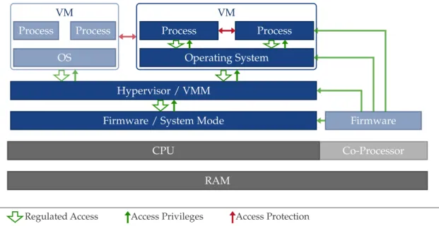
Most computer systems follow a hierarchical protection and management paradigm. Software entities can execute with different privileges, where the privileges of an entity residing higher in the hierarchy are a super-set of the privileges of entities residing lower in the hierarchy. For instance, the Operating System (OS), as the higher privileged entity, has accesses to its own memory and the memory of applications or processes, which are less privileged, while, processes cannot access the memory of theOS. This is enforced via memory access control that is under the OS’s governance (cf. Section2.1.1). This
principal repeats at multiple layers, as illustrated in Figure1.
Similarly, (unprivileged) processes have access only to a subset of Central Processing Unit (CPU) instructions, while additional instructions are only available to privileged software entities, such as theOS. Typically, instructions that are used to configure the system and its resources, e. g., define access rules, are reserved for more privileged entities.
TheCPUcan operate in different modes defining the privilege levels of the software currently in execution.1
The naming of theCPUmodes is platform specific. For instance, on ARM processors the modes are called exception levels and are numbered from lowest privileges (EL0) to highest privileges (EL3). On x86, in contrast, unprivileged code is executed in so-calledring 3, while theOSexecutes inring 0. Following this systematic, higher privileged modes are numbered in descending order, for instance, the Virtual Machine Monitor (VMM) mode is often referred to as “ring -1”.
Transition between differentCPUmodes can be initiated by different events, such as exceptions or interrupts. Also, external events, for instance hardware interrupts, cause a transition to privileged execution mode where interrupts are handled by Interrupt Service Routines (ISRs). Unprivileged entities can also initiate a transition. Typically, this is to request services from theOS, via system calls, by executing dedicated instructions, for examplesysenteror syscallon x86 systems. The OS can return to unprivileged entities using corresponding instructions, e. g.,sysexitor sysret.
The higher privileged software is responsible for managing, i. e., controlling resource access, as well as providing services for less privileged software. When the less privileged software is aware of its limitations and the existence of a higher privileged entity, then it
1 On multi-core systems eachCPU-core can operate in different modes independently.
VM VM
CPU
Firmware / System Mode Hypervisor / VMM Operating System Process Process OS Process Process RAM Co-Processor Firmware Access Privileges
Regulated Access Access Protection
Figure1: Common computer architecture using a hierarchical protection and management
paradigm. Higher privileged entities can access unprivileged entities (unrestricted), while unprivileged entities have no direct access to privileged entities.
explicitly requests services from the higher privileged entity, e. g., an application requests services from theOS through system calls, invoking a predefined function of the OS. Otherwise, the higher privileged entity has to be transparent and needs to emulate the behavior of the underlying system as expected by the less privileged entity. For instance, hypervisors can provide theOSexecuting in a Virtual Machine (VM) the impression of running directly and exclusively on the computer’s hardware.
While the mainCPUand the software executing on it adhere to this hierarchical model, many platforms have additional system components that are orthogonal to this model. For instance, Intel’sCSMEis a co-processor that can access the main memory enabling it to access the data and code of all software entities, regardless of the privilege level [148],
as illustrated in Figure1.
2.1.1 Memory Management and Memory Protection
Memory access control is a central concept for computer security. Limiting the access to memory allows the protection of information’s integrity and confidentiality stored in it. In general, potential malicious or faulty entities should be restricted with respect to the memory locations that they can access. Additionally, for accessible memory location the mode of access should be regulated, e. g., allowing read-only access or execute-only access.
Memory access control can be realized using different approaches, e. g., by testing memory accesses for compliance with a given list of rules or by encrypting the memory content. Subsequently techniques relevant for the rest of this work are described.
MMU wr r1 rdr4 CPU CPU Process 1 Process 2 Virtual Address Space Physical Address Space PT Base PC r1 0x0 0x9 Page Table 0x0 0x9 PT Base PC r4
PC: Program Counter PT: Page Table r1/4: Register 1/4 rd: read wr: write
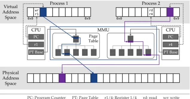
Figure2: The Memory Management Unit (MMU) translates virtual memory addresses to physical
memory addresses. The mapping between virtual memory and physical memory is defined per process and is managed via a hierarchical data structure, called page tables. The root of the currently executing process’ page table is stored in a dedicated CPU-register (PT Base).
Read-Only Memory.Memory that cannot be written to, typically due to its physical properties, provides strong integrity protection of its content. Alternatively, Read-Only Memory (ROM), i. e., memory must not be written to, can be implemented using ap-proaches that enforce access permissions for memory, e. g., using a Memory Management Unit (MMU) or Memory Protection Unit (MPU).
Memory Management Unit.The concept ofvirtual memoryprovides software entities, in particular processes, with a continuous memory space independent of other software entities running on a system. This is achieved by translating all memory access of a process: processes operate on virtual memory addresses which are mapped and translated on the fly to addresses in the computer’s physical memory. Each process has its own virtual memory space, which gets mapped to physical memory locations exclusively reserved to each process. This mapping is managed by privileged software, typically the OS.
Figure2 shows the virtual address space of two processes. The mapping of virtual
memory to physical memory is done in fixed units of memory, called memory pages. For each memory page of the virtual memory space, its mapping to the corresponding memory page in physical memory is stored in a hierarchical data structure, called page table. And for each virtual memory space a separate page table maps virtual memory pages to physical memory pages.
The Memory Management Unit (MMU) is a hardware unit that translates all memory accesses, i. e., for each memory access theMMUsubstitutes the virtual memory address
with the corresponding physical memory address using the page table, as shown in Figure2. The page table to be used by theMMUis specified by aCPU-register. Thus, the
active virtual address space can be defined by updating this register, e. g., theOSupdates it when scheduling a new process.
The page tables define for each memory page access permissions, i. e., the access mode for each memory page. Additionally, not all virtual memory pages need to be mapped to physical memory addresses, virtual pages for which no mapping exist are inaccessible, and thus, providing isolation. For instance, physical memory pages that are mapped to one process’ virtual memory are inaccessible for all other processes that do not have a mapping from their virtual memory space to these physical memory pages. When software tries to access a virtual memory page that is not mapped to a physical page, an exception is raised by theMMUnotifying theOSabout the access attempt.
Swapping.Not having physical memory pages mapped to the virtual memory space of a process is also done for dynamic resource management, allowing theOSto over-provision the system’s physical memory. TheOScan mark virtual memory pages as unavailable, resulting in an exception when the process tries to access that page. During exception handling, theOScan allocate a physical memory page, create a mapping for the virtual memory page that caused the exception and make the virtual memory page as available. Afterwards, the process can continue, using the previous unavailable virtual memory page.
When no physical memory is available, theOShas to re-use a physical memory page that is already allocated and mapped to another virtual memory page, i. e.,swap the memory pages. To prevent data loss, theOScopies the content of the memory page that should be freed to another memory system, e. g., non-volatile memory. When the content of the swapped out memory page is again accessed by its process, theOShas to revert the process, i. e., restore the page’s content to a newly allocated physical memory page and map the process’ virtual memory page to the new physical memory page.
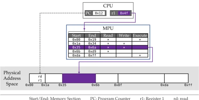
Memory Protection Unit.TheMPUis a hardware unit that provides memory protection by enforcing memory access control policies. It is most commonly used in low-end embedded systems that do not provide virtual memory abstraction, i. e., where all software operates in the physical address space.
The MPU moderates all accesses of the CPU to the memory, as shown in Figure 3.
The access control policies can be defined per memory region, i. e., different parts of the memory can be accessed in different modes. Thus, regions can be marked non-executable or can be marked non-writable.
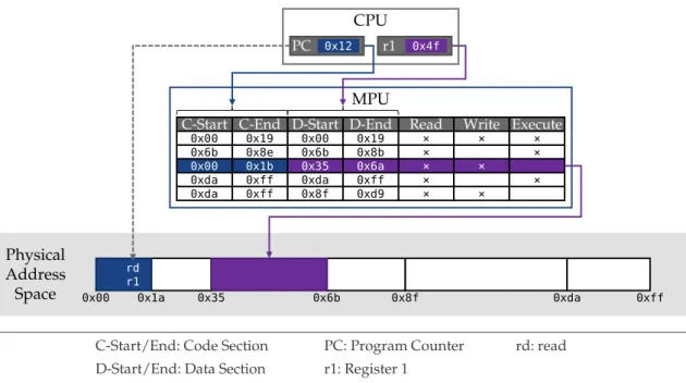
The memory access rules have global validity, i. e.,allrules are enforced regardless of the software entity currently executing. On systems with different execution modes, e. g., privileged and unprivileged mode, often distinct rules for each mode can be defined, e. g., allowing to isolate privileged code and data from unprivileged software’s accesses. Execution-Aware Memory Protection Unit. The EA-MPU extends the concept of MPUs by making itexecution-aware, i. e., it takes the current executing software into account when deciding whether a memory accesses should be allowed or denied [226]. Access
MPU Physical Address Space CPU r1 PC 0x00 0x1a 0x35 0x6b 0x8f 0xda 0xff 0x4f 0x12 rd r1
Start End Read Write Execute
0x00 0x19 × ×
0x1a 0x34 × ×
0x35 0x6a × ×
0x6b 0xd9 ×
0xda 0xff ×
PC: Program Counter r1: Register 1 rd: read Start/End: Memory Section
Figure3: The Memory Protection Unit (MPU) enforces memory access rules, which are defined
per memory regions.
for which an access rule is valid. On each memory access, theEA-MPUchecks whether the currently executing code, identified by the Program Counter (PC) register, lies in the specified code region, in addition to the access mode checks performed by a standard MPU, as shown in Figure4.
This concept allows memory access rules to be defined per software entity, e. g., process or task, independent of privilege levels.
2.1.2 Cache Architectures
In the following we provide details of the Intel x86cache architecture [208, 205].2 We
focus on the Intel Skylake processor generation, i. e., the type of CPU we used for our side-channel attack and defense presented in Chapter4.
Memory caching “hides” the latency of memory accesses to the system’s Dynamic Random Access Memory (DRAM) by keeping a copy of currently processed data in faster memory, called cache. Caches are fast but small memories, which are built into the CPU. Typically, they are realized as Static Random Access Memory (SRAM). AlthoughSRAM caches have better performance compared toDRAMmemory, they cannot be produced at the same density asDRAM, resulting in higher cost. Due to their higher cost (e. g., in terms of production and energy consumption), caches are orders of magnitude smaller thanDRAMand only a subset of a system’s memory content can be present in the cache at any point in time, i. e., to leverage their advantages of both memory types they are used in combination.
MPU Physical Address Space CPU r1 PC 0x00 0x1a 0x35 0x6b 0x8f 0xda 0xff 0x4f 0x12 C-End
C-Start D-Start D-End Read Write Execute 0x19 0x00 0x00 0x19 × × × 0x8e 0x6b 0x6b 0x8b × × 0x1b 0x00 0x35 0x6a × × 0xff 0xda 0xda 0xff × × 0xff 0xda 0x8f 0xd9 × × rd r1 PC: Program Counter r1: Register 1 rd: read C-Start/End: Code Section
D-Start/End: Data Section
Figure4: The Execution-Aware Memory Protection Unit (EA-MPU) enforces memory access rules
depending on the currently executing software, i. e., memory access is only granted to specified software entities, which are identified based on the code region currently being executed.
When a memory operation is performed, the cache controller checks whether the requested data is already cached, and if so, the request is served from the cache, called a cache hit, otherwise cache miss.3
The cache controller aims to maximize the cache hit rate by predicting which data are used next by theCPU. This prediction is based on the assumption of temporal and spatial locality of memory accesses. Temporal locality means that recently used data are more likely to be used soon than data that have not be accessed in a while. Spatial locality describes the assumption that data located next to data currently in use is likely to be used as well. Hence, two types of data should be available in the cache: data that have been used most recently, and data close to those data. The first is accounted for by the cache replacement strategy. The latter is achieved by loading chunks of data into the cache, calledcache line.
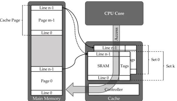
For each memory access the cache controller has to check if the data are present in the cache. Sequentially iterating through the entire cache would be very time-consuming. Therefore, the cache is divided intocache linesand for each memory address the corre-sponding cache line can be quickly determined, typically the lower bits of a memory address select the cache line. Hence, multiple memory addresses map to the same cache line. In Figure5the first line of eachcache pagein memory maps to the first cache line.4
3 For the rest of this work we focus on read operations from data caches. Also, we excludeuncacheablememory from our discussion, i. e., memory regions that are explicitly prevented from being stored in the cache, which is, for instance, required for ensuring coherency with external devices supporting Direct Memory Access (DMA).
Cache Main Memory Controller Page 0 Page m-1 Line n-1 Line n-1 Line 0 Line 0 CPU Core SRAM Tags Line n-1 Line 0 Cache Page Set 0 SRAM Tags Line n-1 Line 0 Set k A cc ess
Figure5: Caches are organized in ways and sets. The cache way is selected based on (a part) of
the memory address of the data to be cached. The sets refer to the number of concurrent cache locations data can be stored.
Having one cache entry per cache line quickly leads to conflicts and the controller has to evict data from cache to replace it with newly requested data. For instance, in Figure5
the first line of cache pages0andm−1are mapped to the same cache line. To minimize such conflicts caches are often (set) associative. Multiple copies of each cache line exist in parallel, also known ascache sets, thus #cachesetsmany data from conflicting memory locations can stay in the cache simultaneously. When the maximum number of allowed conflicts is exceeded, the cache controller must evict data from a cache line to replace it with newly requested data. Which cache line to evict is determined by the cache replacement policy. The “least recently used” policy is often used, i. e., the data that has not been access for the longest time frame is evicted.
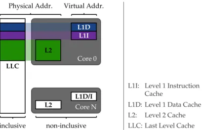
Figure6shows the cache hierarchy of current IntelCPUs, with a three level hierarchy
of caches: The Last Level Cache (LLC), also known as Level3(L3) cache, is the largest and slowest cache; it is shared between all CPU-cores. The Level1(L1) and Level (L2) caches are exclusive to eachCPU-core, i. e., eachCPU-core has a dedicated L1and L2cache. The L1/L2caches are shared between Simultaneous Multithreading (SMT) execution units.5 TheLLCis inclusive, i. e., all data that is present in the L1 or L2cache of any CPU-core is also present in theLLC, as shown forCore0in Figure6. L2cache and theLLC are physically indexed, while the L1 cache is virtually indexed. This means that the L1 cache is accessed and managed based on the virtual memory address as used by the applications directly. When accessing the other caches, virtual addresses first get translated to physical addresses to determine the cache line. Another unique feature of the L1cache is its separation into data and instruction cache. Code fetches only affect the 5 SMTis also known as Hyper-threading (HT) in IntelCPUs.
Core 0 LLC L2 L1D L1I Core N L2 L1D/I
Physical Addr. Virtual Addr.
inclusive non-inclusive L1I: L1D: L2: LLC: Level 1 Instruction Cache
Level 1 Data Cache Level 2 Cache Last Level Cache
Figure6: Cache hierarchy and configuration of Intel Skylake processors. The Last Level Cache
(LLC) is inclusive, i. e., all data stored in any per-core L1/L2 is also stored inLLC.
L1cache is divided into separated parts for data and instructions. The L1cache is
addressed using virtual addresses, while L2and L3caches are addressed by physical
addresses.
instruction cache and leave the data cache unmodified, and vice versa. In L2 andLLC caches code memory and data memory compete for the available cache space.
2
.
2
S
e c u r i t y
S
e r v i c e s
2.2.1 Secure Boot
Secure boot gradually verifies the integrity of a system’s software components while it is starting. Before any component is executed its integrity is checked. The verification process is started by the initial component E0 of the platform’s boot process (e. g., theBIOSorUEFIcode) and iteratively continued by all componentsE1. . . Enthat are executed afterwards (e. g., the boot loader, hypervisor, and the Virtual Machines (VMs)) until the last componentEn+1 has been verified and executed (cf. Figure7).
Root of Trust
(Entity )
Entity Entity Entity Entity
Figure7: Chain of Trust (CoT) concept.
Since the integrity of each componentEiis verified by its predecessorEi−1 before it is executed, only known (i. e., authentic) software components are loaded and executed. When the integrity of a software component cannot be verified, different reactions are possible. For instance, the system may stop execution (also called fail secure mode) or it may use an authentic fallback version of the software component whose integrity check
failed [23]. The integrity verification of a component is meaningful only if the component
that performs the verification itself is benign. Hence, the initial componentE0 must be trusted and is often denoted as Root of Trust (RoT). This means that the integrity ofE0
must be protected against (software) attacks, e. g., by storing the code and data ofE0 in Read-Only Memory (ROM). The integrity of all other componentsE1. . . Enis ensured by the fact that the integrity of every componentEiis verified by its predecessorEi−1
beforeEiis executed.
The method used to verify the integrity of a component depends on the requirements of the application. The most common approach is for the secure boot mechanism to compute an Integrity Measurement Value (IMV), which typically is the cryptographic hash digest, of the binary code of the software component to be verified. TheIMVis then compared to a referenceIMVthat is typically certified by the platform manufacturer, the platform user, or the software provider. If theIMV computed by the secure boot mechanism matches the certified referenceIMVprovided by the software provider, the integrity of the software component is preserved.
2.2.1.1 Order of Integrity Verification
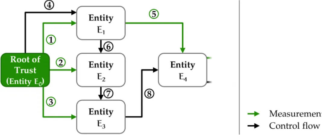
It must be ensured that the integrity of each software component is verified before it is executed. Except for this fundamental rule, there are no other restrictions on the order of the integrity verification and software execution. This means that the integrity of the software componentEncan be verified by any software componentE0. . . En−1 that is executed beforeEn. Root of Trust (Entity ) Entity Entity Entity Entity 1 2 3 4 5 6 7 8 Measurement Control flow Figure8: Integrity validation and execution order in Chain of Trust (CoT).
Figure8illustrates such a scenario, where the integrity of software componentsE1,E2,
andE3 is verified by software componentE0 (1, 2 and 3 in Figure8) beforeE1,E2, or
E3 is executed (4, 6 and 7 in Figure8). Similarly,E1 verifiesE4(5 in Figure8) although
E1 is not loaded directly before E4. Nevertheless, in this example, the integrity of each software component is verified before it is loaded.
2.2.1.2 Reference Measurement Values
The integrity and authenticity of the referenceIMVmust be ensured. Depending on the requirements on the flexibility of the secure boot mechanism, different approaches are possible to store and manage referenceIMVs.
ReferenceIMVs Embedded in Software Components.One approach to manage refer-enceIMVs is to embed the referenceIMVof software componentEiinto the predecessor componentEi−1 that verifies the integrity of Ei, as illustrated in Figure 9. The initial
componentE0includes the referenceIMVofE1denotedM(E1), i. e., the expectedIMVof
E1. The integrity ofM(E1)is protected by the same mechanism that ensures the integrity ofE0 itself. The integrity of the actual software componentE10 is verified by E0 before
E10 is executed. More detailed, E0 computes the hash digest of the binary code of E10, denotedM(E10) (1 in Figure9) and compares the result with the referenceIMVM(E1)
stored inE0 (2 in Figure9). The verification of the integrity ofE0
1 succeeds only ifM(E
0
1) matchesM(E1). If this is the case,E10 is executed (3 in Figure9) and takes over the role
ofE0, i. e.,E10 measures the binary code ofE20 and executesE20 only if its measurement
M(E20)matches the referenceIMVM(E2)of software componentE2, which is stored in
E10. This process is continued until the integrity of all software components has been verified.
Entity Entity Entity
= = 1 2 3 Measurement Verification Control flow
Figure9: Secure boot with embeddedIMVs.
One major limitation of this approach is its lack of flexibility. Specifically, updating software componentEirequires updating the referenceIMVs in all software components
Ej withj < i.
ReferenceIMVs Managed in Central Database.An more flexible approach, compared to the embedding approach described before, is managing the referenceIMVs in a central database, illustrated in Figure10. Before the initial component E0 passes execution to
component E10, it verifies the integrity of E10. Again, E0 measures the binary code of
E10 and compares the resultM(E10)with the referenceIMVM(E1)ofE1. However, this time the referenceIMVis stored in a central database that can be read by all software components performing integrity verification. To ensure the authenticity and integrity of the referenceIMVs, the integrity of the database must be protected. One approach to protect the integrity of the database is using the same method used to protect the integrity of the initial componentE0 or to useE0 to verify the integrity of the database.
Entity Entity Entity = = 1 2 3 Measurement Verification Control flow Figure10: Secure boot with centralIMVs storage.
This method allows the flexible update of individual software components. However, updating software components requires updating the corresponding referenceIMVs in the database in an authentic way.
Certified ReferenceIMVs.The most practical approach to implement secure boot to is using digital signatures (certificates) to ensure the integrity and authenticity of refer-enceIMVs. This approach is shown in Figure11. The referenceIMVof every software
component is contained in a digital certificate issued by a signing authority. The signing authority might be the platform manufacturer, platform user, and/or a software provider. The certificate does not need to be stored in protected memory since its authenticity is ensured by a digital signatureσpk issued by the signing authority. Before the initial componentE0 passes execution toE10, it verifies the integrity ofE10. Again,E0 measures the binary files ofE10 and comparesM(E10)to the referenceIMVM(E1)ofE10, which is included in the certificate. The authenticity of the referenceIMVis checked by verifying the certificate using the authentic public verification keypkof the signing authority.
Entity Entity Entity
= = 1 2 3 ver ver Measurement Verification Control flow Figure11: Secure boot withIMVcertificates.
When updating a componentEn, a new certificate must be issued for the version ofEn
and stored on the platform. Since the certificate can be validated with the same public verification keypk, neither entityE0 nor the protected memory containingpkmust be
updated. SinceE0 and pkneed to be updated rarely or even never during the lifetime of the platform, simple hardware-based protection such asROMcan be used to protect their integrity and authenticity.
Revocation. In secure boot systems, revocation might be necessary either because an entityEnis no longer trustworthy and should not be allowed to be executed, e. g., because a vulnerability was discovered in its code and an update versionE∗n has been released, or a signing key, used to authenticate code certificates, was compromised.
In the first case, the measurement M(Ei) must be removed and replaced with an updated measurementM(E∗i). Depending on the secure boot variant used, this requires updatingEi’s predecessor components with an updated embeddedIMVs (M(E∗i)), up-dating the centralIMVstorage or issuing a new certificate forM(E∗i). In all variants the authenticity of the updates must be ensured.
In the second case, the secure boot system must learn that the compromised key can no longer assert the integrity of any entityEn, or the authenticity and integrity of other keys, e. g., when a Public Key Infrastructure (PKI) is used in the secure boot system.
In all cases the revocation information must be made available to the secure boot system. If a device is not compromised, it can retrieve the updated information over the network, e. g., in form of a Certificate Revocation List (CRL) to revoke certificates [105].
A device under an adversary’s control, e. g., a device on which the adversary exploited a vulnerability in an entityEi, will not voluntarily update the revocation information. In these cases, the update must be enforced, for instance, certificates can be issued with an expiration date rendering updates mandatory after the certificate validity period. How-ever, these solutions require that the secure boot system can receive updated information, e. g., via network. Further, to prevent attacks, such as roll-back attacks, devices need to store the latest revocation information securely or maintain version information using a secure monotonic counter. To ensure up-to-date revocation information, devices need access to reliable time information.
If a secure boot system’sRoTis compromised, e. g., ifE0 is insecure, theRoTmust be replaced or updated [289], which is impossible in many systems.
2.2.2 Attestation
Attestation enables one entity, calledverifier, to gain assurance about the state of another entity, calledprover. The rationale behind attestation is to verify that the prover is in a correct state and is therefore trustworthy, i. e., attestation is often used to bootstrap trust in the prover.
Typically, the state of a device is defined by its memory content. In particular, the memory that is determining the behavior of a computing device is considered, i. e., memory containing the provider’s program code, such as binary code loaded in Random Access Memory (RAM). This type of attestation is also calledbinary attestationorstatic attestation, as it captures the static state of the prover, allowing the detection of malware infections and other attacks that alter the code memory of a prover device [382, 139].
attacks, can only be captured by approaches that record and report the run-time behavior of the prover device, calledrun-time attestation[3,130,129,416].
The correct state of a prover device can be defined arbitrarily, however, in practice the state is typically considered correct if it conforms with the manufacturer’s specifications for the prover device, i. e., if the state has not been altered in an unauthorized way.6
Most attestation mechanism represent the prover’s state in a compressed form, typically, the state is fed into a cryptographic hash function to map it to a short, fixed size value. The verifier usually is assumed to know all hash values representing correct states, hence, the verifier can decide, based on the value provided by the prover, whether the prover is in a correct state.
For the verifier, to be able to establish trust in a prover device based on the reported state, the following necessary conditions must hold. (1) binding between state mea-surement value and prover authentic identity, (2) integrity of state measurement value, (3) freshness of state measurements, (4) trustworthy state capture mechanism, (5) unpre-dictable time of attestation, i. e., the time of attestation must be unknown in advanced to a potential adversary, and (6) equality of the prover’s state and its measurement regarding prover’s correctness.
In different systems and scenarios these requirements can be assumed or can be met by different means.
Local attestation scenarios rely on a trusted link or channel between prover and verifier, e. g., a connection via a dedicated physical wire which is assumed to be untampered. Hence, the authenticity of the prover entity and the integrity of the transmitted mea-surement value can be assumed. In Remote Attestation (RA) schemes, the authenticity of the prover and the integrity of the transmitted measurement value must be ensured by other means. This can be done, for instance, using a digital signature or Message Authentication Code (MAC), however, the key used to authenticate the prover must be protected such that it is only accessible to trusted entities and each prover needs to have a unique cryptographic key. Additionally, the signature/MACbinds the measurement value to the prover’s identity.
The freshness of a state measurement can be achieved by integrating a nonce in the measurement that cannot be foreseen by a potential adversary and for which the verifier can validate that it is timely, otherwise the adversary can pre-compute a valid attestation report or reuse a previous report. Either the verifier sends a fresh nonce to the prover, i. e., the verifier knows when the nonce was disclosed to the prover, or a nonce is generated in a trustworthy way on the prover device. If the verifier initiates the attestation process, it can follow a strategy unknown to the adversary. However, if the prover reports its state independent of verifier requests it is important that an adversary can neither influence this process, e. g., prevent or delay the reporting, nor foresee the attestation time, i. e., allowing aroaming adversaryto leave the prover device reverting all its changes before attestation is performed (cf. Section6.1.1.2).
The measurement reported to the verifier must be correct, i. e., an adversary must not be able to tamper with the measurement process. In particular, the integrity of 6 Authorized alterations of a device’s software, e. g., due to a software update, usually should not lead to an
the component performing the measurement must be ensured, otherwise the verifier cannot trust the attestation report. Additionally, the temporal integrity of the measured state must be ensured while the measurement is being performed [84]. The integrity
of the measurement component is achieved in different ways by differentRAschemes. ExistingRAapproaches can be divided into three categories: (i) software-based attestation, (ii) hardware-based attestation, and (iii) hybrid software/hardware-bases attestation. In hardware-based and hybrid attestation solutions the measurements engine’s integrity is ensured, e. g., by isolating it in an isolated execution environment such as a co-processor or in a Trusted Execution Environment (TEE). The same protection mechanism can also be used to protect cryptographic keys to authenticate the prover to a remote verifier and protect the integrity of an attestation report when transmitted via network. Software-based attestationrelies only on unprotected software to measure the state of the prover device. Hence, the integrity of the measurement engine cannot be guaranteed. The integrity of the measurement engine is tested using its execution characteristics, such as its timing behavior. The assumption is that the measurement engine is time-optimal, i. e., no faster way of measuring the prover’s state exists, thus, if an adversary manipulated the measurement engine, its run time increases, which will be detected by the verifier. However, these timing assumptions only hold if the adversary is limited to the prover device’s unaltered resources for generating an attestation report. If the adversary, for instance, increases the processing speed of the prover or receives assistance in the computations from another device, these underlying assumptions do not hold, and hence, software-based attestation cannot provide the required security guarantees. Furthermore, the lack of protection capability averts the usage of cryptographic methods to authenticate and protect the integrity of attestation reports, as the required cryptographic keys cannot be protected from unauthorized access by the adversary.
2
.
3
S
e c u r i t y
A
r c h i t e c t u r e s a n d
T
r u s t e d
E
x e c u t i o n
E
n v i r o n m e n t s
2.3.1 ARM TrustZone
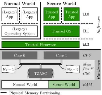
TrustZone represents a set of security enhancements to ARM’s processor and System-on-Chip (SoC) designs. TrustZone extends the processor, memory system (including caches), and peripherals. A TrustZone-enabled processor can execute in two security modes at any given time. The two modes are callednormal worldandsecure world, respectively. The normal world retains backwards-compatibility and hosts all software that is not explicitly made for the secure world. All security critical software is meant to be isolated in the secure world, protected from the untrusted software in the normal world. The secure and normal world both manage their own address spaces using the traditional privilege levels for separation of the Operating System (OS) kernel and application code (cf. Section2.1).
More specifically, current ARM processors provide four privilege levels (Exception Levels–
EL0toEL3). The normal world providesEL0(unprivileged applications),EL1(privileged OS), andEL2(hypervisor, also privileged). In the secure world, two privilege levels (S-EL0
(Legacy) App (Legacy) App Trusted App Trusted App (Legacy)
Operating System Trusted OS
Trusted Firmware
S
oft
w
are
Physical Memory Partitioning Virtual Memory Isolation
EL0 EL1 EL3 NS = 0 NS = 1 Core 0 Core 1 TZASC Secure World Normal World Hard ware CPU RAM Mem Bus & Ctrl
Normal World Secure World
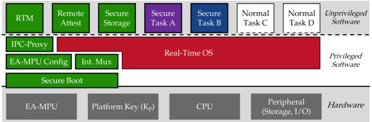
Figure12: TrustZone software and hardware components. Software can be executed innormal
worldor insecure world. Isolation between these two worlds is enforced by the memory controller (TZASC) that checks for each memory access which world it originates from.
andS-EL1) are available in current ARM architectures.7
The highest privileged modeEL3, also calledmonitor mode, executes the ARM Trusted Firmware (TF).
Typically, the normal world hosts the user facing software, including a smartphone OS, e. g., Android [172], and applications (often abbreviated “apps” in the context of
smartphones). In the secure world a Trusted OS (TOS) is running that manages the Trusted Apps (TAs), see Figure12.
Each processor core can switch from normal to secure world via a dedicated secure monitor call (smc) instruction. When ansmcinstruction is invoked from normal world, the processor core performs a context switch to the secure world (via the monitor mode), the execution of the normal world is suspended while the secure world is executing. In a multi-core system, each processor core can independently execute in any of the modes, i. e., at any privilege level (EL0toEL3) in either world.
TrustZone can separate physical memory into two partitions, with one partition being exclusively accessible by the secure world. This isolation is enforced by the memory controller (TZASC) that evaluates for every memory transaction whether it originates from the secure world or the normal world. This evaluation is done based on an addition flag included in each transaction, called the non-secure flag (NS), indicating that the transaction was issued by a processor in normal mode (normal world, NS=1) or in secure mode (secure world,NS=0). Accesses to the memory partition reserved for the secure world is only granted if the processor issuing the access is executed in
secure-7 Future versions of the ARM architecture will supportS-EL2, i. e., hardware virtualization in the secure world [31].