Symphony: View-Driven Software Architecture Reconstruction
Arie van Deursen
CWI & Delft Univ. of Technology The Netherlands [email protected]
Christine Hofmeister
Lehigh University USA [email protected]Rainer Koschke
University of Stuttgart Germany [email protected]Leon Moonen
Delft Univ. of Technology & CWI The Netherlands
Claudio Riva
Nokia Research Center Helsinki, Finland [email protected]
Abstract
Authentic descriptions of a software architecture are re-quired as a reliable foundation for any but trivial changes to a system. Far too often, architecture descriptions of exist-ing systems are out of sync with the implementation. If they are, they must be reconstructed.
There are many existing techniques for reconstructing in-dividual architecture views, but no information about how to select views for reconstruction, or about process aspects of architecture reconstruction in general. In this paper we de-scribe view-driven process for reconstructing software archi-tecture that fills this gap. To describe Symphony, we present and compare different case studies, thus serving a secondary goal of sharing real-life reconstruction experience.
The Symphony process incorporates the state of the prac-tice, where reconstruction is problem-driven and uses a rich set of architecture views. Symphony provides a common framework for reporting reconstruction experiences and for comparing reconstruction approaches. Finally, it is a vehicle for exposing and demarcating research problems in software architecture reconstruction.
1.
Introduction
Many software engineering tasks are hard to conduct without relevant architectural information. Examples include migra-tions, auditing, application integration, or impact analysis.
To illustrate the latter, consider the “Basel II” agreement of the Basel Committee on Banking Supervision which regu-lates financial risk estimation and reporting.1 Analysts from
Forrester research have estimated that migrating to “Basel II” will cost banks such as ING or Deutsche Bank approximately 115 million Euros. 60% of these costs concern changes to the bank’s information systems. Such high impact changes can-not be made without a clear picture of the architecture of the underlying information systems.
1Seewww.bis.org/bcbs/andwww.forrester.com
In an ideal world, the relevant architectural information is documented at the time architectural decisions are made, updated whenever these decisions are revised, and readily available when needed for a particular task. Unfortunately, architectural information, when available at all, is often out-dated and incorrect, or inappropriate for the task at hand.
Software architecture reconstruction is the process of ob-taining a documented architecture for an existing system. Al-though such a reconstruction can make use of any possible resource (such as available documentation, stakeholder terviews, domain knowledge), the most reliable source of in-formation is the system itself, either via its source code or via traces obtained from executing the system.
Architecture reconstruction in practice has been pre-dictably ad-hoc, using simple tools and a large amount of manual interpretation. Researchers have been trying to im-prove the state of the practice primarily by providing better techniques and tools (e.g., cluster or concept analysis, pro-gram analysis, and software visualization). The application of these techniques usually involves three steps: extract raw data from the source, apply the appropriate abstraction tech-nique, and present or visualize the information obtained.
Although research papers presenting reconstruction tech-niques typically describe the steps needed for the successful application of one specific technique, a number of questions remain. What problems require architecture reconstruction? What are typical views that should be recovered? Which techniques are suitable for reconstructing particular views? How can different views be presented so that they actually hepl to deal with the problem at hand? In this paper we pro-pose Symphony, a method that aims at helping reconstruc-tion teams in answering such quesreconstruc-tions.
Symphony2is the result of a systematic analysis of (1) our
own experiences in software architecture reconstruction, (2)
2 The name Symphony reflects that a successful reconstruction is the result of the interplay of many different instruments. Moreover, the authors’ collaboration in the area of software architecture reconstruction started in the music room of Castle Dagstuhl in Germany.
cases conducted by close colleagues, and (3) the various ap-proaches that have been published in the literature. In partic-ular, the paper integrates four different reconstruction cases carried out by the authors. These cases are used throughout the paper to illustrate each step of Symphony. They are de-scribed in more detail in the appendix that is contained in the full technical report [5].
Moreover, the case studies demonstrate the importance of viewpoints in focusing the reconstruction activities to solve a particular problem. Different viewpoints and correspond-ing techniques were used in all case studies, underlincorrespond-ing the need to recognize viewpoints as first-order elements of any architecure reconstruction process.
Having a method like Symphony can help practitioners by giving them guidance in performing an architecture recon-struction. In addition, Symphony provides a good concep-tual framework for comparing case studies. It can help re-searchers by providing a unified approach to reconstruction, with consistent terminology and a basis for improving, refin-ing, quantifyrefin-ing, and comparing reconstruction processes.
Furthermore, the Symphony method is view-based in recognition of the importance of multiple architectural views not only in presenting architecture but more fundamentally in defining the reconstruction activities. Previous research has focused on recovering a single architectural view or a few preselected views. Part of the Symphony process is the dis-covery of the views that should be reconstructed in order to solve the problem at hand.
This paper is organized as follows. First we summarize related work in Section 2. Then, we define our terminol-ogy on architectural views in Section 3. In Section 4 we provide an overview of the Symphony steps, which are then described in Sections 5 and 6. In Section 7 we summarize our contributions and opportunities for future work.
2.
Related Work
Software architecture reconstruction is an active area of search, as illustrated by the recent software architecture re-construction workshops held in conjunction with the Work-ing Conference on Reverse EngineerWork-ing in 2001, 2002, and in 2003 in Dagstuhl, as well as the workshops organized by the SEI on asset mining for software product lines.
Although there is a substantial body of published work in the area of reverse architecting, we are not aware of other pa-pers addressing the software architecture reconstruction pro-cess per se. In this section, we summarize those papers that deal with software architecture reconstruction and discuss the process elements covered by them. Note that a signifi-cant amount of related work is furthermore discussed in our presentation of the various Symphony steps.
Software architecture reconstruction is a special form of software reverse engineering. Many reverse engineering
ap-proaches are based on an extract–abstract–present cycle, in which sources are analyzed in order to populate a reposi-tory, which is queried in order to yield abstract system repre-sentations, which are then presented in a suitable interactive form to the software engineer. Tilley et al. [32] describe the extract–abstract–present approach in more detail, refer-ring to the steps as data gatherefer-ring, knowledge inference, and
information presentation.
A number of reverse engineering activities focus on soft-ware architecture reconstruction. Kazman et al. [12] pro-pose an iterative reconstruction process where the histori-cal design decisions are discovered by empirihistori-cally formulat-ing/validating architectural hypotheses. They also point out the importance of modeling not only system information but also a description of the underlying semantics [12]. Their approach is currently extended to include the reorganization of recovered assets into software product lines [31].
Finnigan et al. [11] propose the Software Bookshelf: a toolkit to generate architecture diagrams from source text.
Ding and Medvidovic describe the Focus approach, which contrasts a logical (idealized, high-level) architecture with a
physical (as implemented, as recovered) one [9]. By
apply-ing refinement to the logical and abstraction to the physical architecture, the two are brought together incrementally.
All the previous works differs from Symphony in that they address a determined goal, concrete techniques, and a certain fixed sets of views to be reconstructed, whereas Symphony provides a general reconstruction model.
3.
Views in Symphony
Software architectures are generally described by models and their rationales. The goal of Symphony is to reconstruct such models (and their rationales if possible). These models are created using viewpoints and presented using views.
3.1.
Views and Viewpoints
A view is a representation of a whole system from the per-spective of a related set of concerns [16]. While it is now generally accepted that the architecture description should be composed of multiple views, the terminology related to views is not yet widely accepted. In this paper, we refer to the IEEE 1471 standard [16].
In IEEE 1471, a view conforms to a viewpoint. While a view describes a particular system, a viewpoint describes the rules and conventions used to create, depict, and analyze a view based on this viewpoint [16]. A viewpoint specifies the kind of information that can be put in a view.
The use of architectural viewpoints and views is a key as-pect of Symphony. In forward design, different architectural viewpoints are useful for separating engineering concerns, which reduces the complexity of design activities. When the resulting design is captured in separate views, this separation
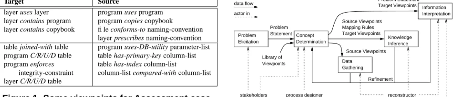
Target Source layer uses layer
layer contains program layer contains copybook
program uses program program copies copybook file conforms-to naming-convention layer prescribes naming-convention table joined-with table
program C/R/U/D table program enforces
integrity-constraint layer C/R/U/D table
program uses-DB-utility parameter-list table has-primary-key column-list table has-index column-list
column-list compared-with column-list
Figure 1. Some viewpoints for Assessment case.
of concerns helps stakeholders and architects understand the architecture.
For architecture reconstruction, multiple viewpoints and views are also beneficial. Different viewpoints help the ar-chitect determine what information should be reconstructed in order to solve the problem. The existence of a library of viewpoints found to be generally useful gives the architect a basis for reasoning about how different kinds of architectural information shed light on the problem. Separation of con-cerns still plays a role, but now in allowing the architect to reason separately about how each viewpoint could contribute to a solution of the problem.
3.2.
Source, Target, and Hypothesis
A source view is a view of a system that can be extracted from artifacts of that system, such as source code, build files, configuration information, documentation, or traces.
Some source views discussed in this paper are at such a detailed level that they are not generally considered to be architectural views. For instance, the source view may cover abstract syntax trees and control flow graphs.
A target view is a view of a software system that describes the as-implemented architecture and contains the informa-tion needed to solve the problem/perform the tasks for which the reconstruction process was carried out.
A hypothetical view describes the architecture of the sys-tem, but perhaps not accurately. It can be a reference or a designed architecture used to check conformance of the implemented architecture to a norm. It can be a postulated architecture, describing the current understanding of the ar-chitecture of a system, and used to guide the reconstruction. This view is typically created by interviewing the system ex-perts or by examining the existing documentation.
To illustrate the roles of source, target, and hypothetical views we take a look at a reconstruction conducted as part of a quality assessment of a system written mostly in Cobol.
The hypothetical view case consisted of the documenta-tion and presentadocumenta-tions offered by the system supplier, who argued that there was no reason for concerns on the qual-ity of the system because of the layering, customization, and data handling mechanisms that were included in the archi-tecture. It was used to guide the design of the target model and for finding potential architectural violations.
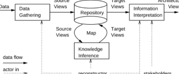
Refinement Problem Statement
process designer reconstructor Source Viewpoints stakeholders actor in data flow Information Interpretation Target Viewpoints Mapping Rules Problem Statement Problem Elicitation Concept Determination Source Viewpoints Knowledge Inference Data Gathering Library of Viewpoints Target Viewpoints
Figure 2. Interaction during reconstruction design.
A selection of the relations contained in the source and
target views is shown in Figure 1. The relations are grouped
in a module viewpoint (first row) and a data viewpoint (sec-ond row). The target view provides an architectural perspec-tive of the system as implemented, while the source view includes those relations that can be readily derived from the system’s source code. As an example, the target model cludes CRUD (Create, Read, Update, Delete) information in-dicating how components manipulate data elements. In some cases, this information may be directly available from the sources (e.g., program file contains SQL statement). In the system at hand, the source model was more complex, since data manipulation was encapsulated in (generated) data util-ities, requiring analysis of control (who calls these utilities) and data flow (what parameters are passed to the utility).
The target model recovered helped to identify layering vi-olations, data integrity checks that were bypassed, and ad hoc mixture of custom and product code complicating upgrades to future product releases.
4.
Symphony Steps
Symphony has two stages. During Reconstruction Design, the problem is analyzed, viewpoints for the target views are selected, source views are defined, and mapping rules from source to target views are designed. The Reconstruction
Ex-ecution analyzes the system, extracts the source views, and
applies the mapping rules to populate the target views. Typically the two stages are iterated: Reconstruction exe-cution reveals new reconstruction opportunities, which lead to a refined understanding of the problem and a refined re-construction design. The source viewpoints, target view-points, and mapping rules evolve throughout the process.
The outcomes of Symphony are twofold: Reconstruction
Design results in a well-defined procedure for reconstructing
the architecture of the system. This procedure may be useful beyond the scope of the current reconstruction: it can play a role in continuous architecture conformance checking and in future reconstructions. Reconstruction Execution yields the architecture description needed to solve the problem that triggered the original reconstruction activity.
Views Views Target Views Views Architectural stakeholders Data reconstructor Repository Data Gathering actor in data flow Knowledge Inference Target Source Information Interpretation Map Views Source
Figure 3. Reconstruction execution interactions.
The various Symphony reconstruction steps are illustrated in Figures 2 and 3. Design steps include Problem Elicitation and Concept Determination, and are discussed in Section 5. Execution steps include Data Gathering, Knowledge
Infer-ence, and Information Interpretation, discussed in Section 6.
5.
Reconstruction Design
During reconstruction design we distinguish problem
elici-tation in which the problem triggering the reconstruction is
analyzed and discussed with stakeholders, and concept
de-termination, in which the architectural concepts relevant to
the problem at hand and a recovery strategy are identified.
5.1.
Problem Elicitation
Reconstructing architectures requires software architecture experts to study a system and an active involvement of stake-holder representatives, such as testers, developers, manage-ment, the business owning the system, and system users. These people are usually in strong demand in other places of the project or the organization. Therefore, there must be a compelling reason to start a reconstruction. Typical rea-sons include performance problems, high maintenance costs, poor reliability, and considerations concerning system re-placement or system extensions. These reasons can typically be collected in a short (one or two page) memorandum offer-ing a management perspective on the problem at hand.
This memorandum forms the starting point for a software reconstruction activity, and the first step is to elaborate this problem statement. This is the purpose of Symphony’s
Prob-lem Elicitation step and requires the involvement of more
technical people in the problem analysis.
In our experience, individual technical people involved in system development typically have a fairly good idea of specific technical problems in their area of expertise (e.g., database administration, networking, user interfaces). In the problem elicitation step these different perspectives should be integrated into one overall picture.
There are several techniques that can be used during prob-lem elicitation, such as structured workshops, checklists, role playing, and scenario analysis. As an example, in the assess-ment case discussed previously, we started with a workshop for which all stakeholders were invited. In this particular
case, each participant was asked to report his best and worst experience with the system analyzed.
Outcomes of Symphony’s Problem Elicitation step in-clude summaries of interviews, workshop sessions, and rele-vant discussions; summaries of available high-level relerele-vant documentation, if available; an elaboration and refinement of the problem statement based on these summaries; and an initial list of documentation and other resources that can be used during the reconstruction.
Observe that the original memorandum, the collected summaries and the refined problem statement may very well be “architecture-agnostic”: they must be expressed in terms familiar to the stakeholders. The translation of the problems-as-perceived to software architecture concepts is the purpose of the “concept determination” step.
The diversity of motivations for architecture reconstruc-tion is exemplified by the four different case studies that lead to the design of Symphony. Two of them, namely, the Assessment and Nokia case, are true industrial cases. The other two were conducted in an academic—nevertheless realistic—setting to better understand architecture recon-struction. As mentioned earlier, a more detailed description of the case studies can be found in the appendix which is contained in the full technical report [5].
Assessment case. The Assessment case (partly described in [7]) involves an assessment of the quality characteristics of a commercial software product written mostly in Cobol that was being customized for a particular client. In the course of the customization process (which took two years) the client grew more and more concerned about the data integrity, reli-ability, and maintainability. An independent assessment was commissioned which should help to decide whether to con-tinue the project. Source code and documentation were avail-able for use in this assessment.
Nokia case. The products of Nokia are typically organized in product families in order to reduce the development costs and maximize the reuse of the assets. The architects’ needs can be summarized as follows: (1) comprehending the as-implemented architecture of the products, (2) managing the organization of components and their logical dependencies in the platform, and (3) enforcing conformance to architec-tural rules. The main goal is to provide the architects with up-to-date information by reconstructing the same architec-tural views that they typically use during design.
Compiler case. In this case, the as-built architectures of two large and complex compilers were to be compared against a reference architecture. Although the actual moti-vation was to evaluate an extension to the original reflexion method by Murphy et al. [21], the case study can indeed be viewed as a realistic task in which an as-built architecture is to be compared against an idealized architecture.
Duke’s Bank case. The goal of this reconstruction was to understand Duke’s Bank and to determine the abstractions to
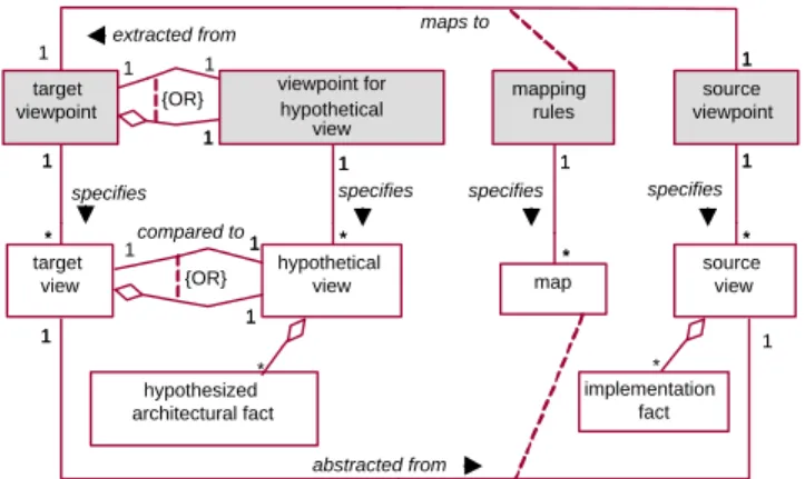
mapping rules 1 1 specifies {OR} source viewpoint 1 1 specifies target viewpoint 1 1 1 maps to 1 1 specifies compared to viewpoint for hypothetical view 1 1 1 1 extracted from 1 1 specifies map ** {OR} implementation fact source view * ** target view 1 1 1 abstracted from hypothesized architectural fact ** hypothetical view 1 1 1 1 1 * **
Figure 4. Viewpoints and Views in Symphony
use in such a system. The motivation was to learn how to reconstruct so that it can be done more efficiently for future examples. An additional challenge in this case study was to exercise the reconstruction with off-the-shelf tools, such as Rational Rose, grep, emacs, etc.
5.2.
Concept Determination
Once the problem is understood, the Concept Determina-tion step is used to determine the architectural informaDetermina-tion needed to solve the problem and the way to derive this in-formation. In this step, the architect is a process designer, defining the architectural reconstruction that will take place in the final three steps.
There are five outcomes of this step, each of which is de-scribed in the remainder of this section. The UML diagram in Figure 4 summarizes the relationships involving the view-points and mapping rules produced in this step.
Identify Potentially Useful Viewpoints. The first step to-wards defining the target viewpoint is to identify a set of viewpoints that contain the information the stakeholders be-lieve will be needed to solve the problem as described in
Problem Elicitation. Stakeholders typically know which
viewpoints will be useful, or have at least some initial ideas. After getting input from the stakeholders, the archi-tect should review the problems and questions, looking for additional useful viewpoints. Although the architect is re-sponsible for producing the list of viewpoints, ultimately the stakeholders must agree to them.
These viewpoints can come from a library of well-known viewpoints, or a new viewpoint can be created for a spe-cific reconstruction. If the problem is not understood well enough to identify viewpoints of interest, the Problem Elici-tation step should be re-applied.
One of the most commonly used viewpoints for architec-ture reconstruction is the Module viewpoint [14]. It identifies the layers, subsystems, and modules in the system and de-scribes relationships (e.g. usage-dependency and decompo-sition) among them. Other common viewpoints are the Code architecture viewpoint, which describes directory structure
and build relationships, and the Execution viewpoint, which describes the runtime entities and their mapping to physi-cal resources [14]. The Conceptual viewpoint [14], describ-ing the functionality of the system in terms of components and connectors, is less commonly used for reconstruction be-cause it is a more abstract view and is therefore more difficult to reconstruct. (See also [4] for examples of Styles, which is their term for viewpoints.)
The Module viewpoint was also used for all four case studies. The Nokia and Duke’s Bank cases used the Code, Execution, and Conceptual viewpoints in addition, whereas the Assessment case study used two other viewpoints (Data and Customization) in addition to the Module.
For reconstruction it may be useful to create new view-points, ones which are not used in forward design. An exam-ple is the Reflexion Model used by Murphy and Notkin [27]. Their Reflexion Model is based on the usage-dependency relationship in the standard Module viewpoint. It contains three relationships (convergence, divergence, absence) that indicate whether the usage-dependencies reflected in the source code conform to those in the hypothetical view.
Define/Refine Target Viewpoint. As Figure 4 shows, the target viewpoint specifies the target view that will be an out-put of the reconstruction process. The stakeholders should also agree to the target viewpoint.
One useful approach for creating the target viewpoint is to use the Stakeholder/View tables described in [4], adapted somewhat for reconstruction. In its original form this is a three-step process culminating in a prioritized list of views needed for documenting a software system.
In Symphony, the first step, producing a candidate view list, begins with the potentially useful viewpoints already identified. Each of these should be listed along with the ex-tent to which it is important for solving the problem. The sec-ond step is to identify the specific relationships of each view-point that are needed. The third step is to prioritize these re-lationships and eliminate any duplicates. During this process the architect should be thinking about similarities among the relationships, which can be derived from others, which are most critical to solving the overall problem, and should try to consolidate them to arrive at the set of relationships in the target viewpoint.
Not all relationships in the target viewpoint will come from a standard viewpoint. For example, the Duke’s Bank case is a J2EE application, where one servlet can “forward” to another, and a jsp can “include” another. These were ini-tially covered by adding a “module forw/incl/etc. module” relationship to the target viewpoint. (In a later refinement this relationship was combined with the usage-dependency relationship, but that determination could not safely be made at the outset.)
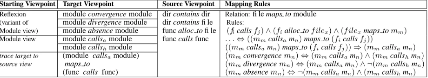
As another example, Figure 5 summarizes the Mur-phy/Notkin Reflexion work in terms of Symphony. Here the
Starting Viewpoint Target Viewpoint Source Viewpoint Mapping Rules
Reflexion module convergence module dir contains dir Relation:file maps to module
(variant of module divergence module dir contains file Rules:
Module view) module absence module func alloc to file (ficallsfj)∧(fialloc tof ilex)∧(f ilexmaps tomm) Module view module callsamodule func calls func . . .⇔((mmcallsamn)maps to(ficallsfj))
module callshmodule ((mmcallsamn)maps to(ficallsfj))⇒(mmcallsamn)
trace target to (module callsamodule) (mmconvergencemn)⇔(mmcallsamn)∧(mmcallshmn)
source view maps to (mmdivergencemn)⇔(mmcallsamn)∧ ¬(mmcallshmn)
(func calls func) (mmabsencemn)⇔ ¬(mmcallsamn)∧(mmcallshmn) Figure 5. Viewpoints and Mapping Rules Used in Reflexion Example
target viewpoint contains relations extracted from the Mod-ule and Reflexion viewpoints.
The Compiler case study used the Reflexion work as a starting point, so initially its target viewpoint was the same as in Figure 5. However, during the course of the recon-struction it became clear that the target viewpoint needed to be modified to support hierarchies of modules, so in a sec-ond iteration the relationship “module contains module” was added.
Define/Refine Source Viewpoint. The source viewpoint specifies the source view. The source view will contain in-formation extracted from the source code and gathered from other sources; the source viewpoint formally describes this information. The challenge in defining a source viewpoint is to determine what information will be needed in order to create the target views. Thus defining the source viewpoint needs to be done in conjunction with defining the mapping from source to target viewpoint.
In the Reflexion example (Figure 5), the source view-point contains some architectural and some lower-level in-formation, but all of it can be directly extracted from the code. This was not true for all of our case studies: al-though automatically-extractable facts formed the basis of the source viewpoint in all, a few relied in addition on re-lationships that can be populated only by manual interpreta-tion of the sources. For instance, in the Compiler case, we had to inspect the results of an overly conservative automatic pointer analysis to filter out obviously wrong results.
The Assessment case study had a second iteration to re-fine the source viewpoint. In the first iteration the definition of the source viewpoint was driven by the information exist-ing tools could produce. Since this was inadequate for pro-ducing the desired target viewpoint, a second iteration was used with a refined mapping and an expanded source view-point.
Define/Refine Mapping Rules. The mapping rules are ideally a formal description of how to derive a target view from a source view. Realistically, parts will often be in the form of heuristics, guidelines, or other informal approaches. If a mapping can be completely formalized, the reconstruc-tion can be fully automated. As said earlier, this is not typ-ically possible for software architecture, thus we expect the mapping to contain both formal and informal parts.
Figure 4 shows that the mapping rules specify the map. The ’mapping rules’ entity is an association class connect-ing the target viewpoint and source viewpoint. Thus it de-scribes the ’maps to’ association between these two entities. The map, as the instantiation of the mapping rules, describes how specific implementation facts in the source view are ab-stracted to architectural facts in the target view.
In the four case studies and the Reflexion example the mappings all contain some informal parts. In the Reflex-ion example and the Assessment case study, the relatReflex-ion “file
maps to module” must be manually populated to produce the map. However, the rest of the mapping is a set of for-mal rules used to compute the target views (Figure 5). Sim-ilarly, the mapping in the Nokia case study relies primarily on a series of transformations formalized in relational alge-bra. At the other extreme, the mapping in the Duke’s Bank case study contains a number of rules about how entities in J2EE applications are related, but they provided only partial information for creating the map. Most of the map creation was done manually.
Determine Role and Viewpoint of Hypothetical Views.
In addition to the above activities, the stakeholders and archi-tect must determine whether a hypothetical view is needed and what its role will be. This role depends on the purpose of the reconstruction. The most common roles of a hypothetical view are as a guide during the reconstruction activity and as a baseline to compare with the system’s current architecture. When serving as a baseline there are two ways the
com-parison can be done. One is to create an explicit
com-parison view, with the comcom-parison embodied in the tar-get view. The Reflexion example and the Compiler case study have such a target view: it identifies modules, usage-dependencies among them, and identifies which of these usage-dependencies match those in the hypothetical view and which do not. In Figure 5 part of the target viewpoint is thecallshrelation, which specifies the hypothetical view (called the ’high-level model’ in [27]).
The second way to use a hypothetical view as a baseline is informally. In this case it is used in the last step, Information Interpretation. Typically the architect browses both the target view and hypothetical view, compares them, and based on the results may decide to perform another iteration of the re-construction process, modifying the target viewpoint, source viewpoint, mapping, or some combination of these.
The Nokia and Assessment case studies used a cal view both for guidance and as a baseline. The hypotheti-cal view guided the definition of the target viewpoint, helped in populating the map, and served as a baseline during Infor-mation Interpretation.
The hypothetical view also has a viewpoint that must be defined. If the hypothetical view is embedded in the target view (as in the Reflexion example) then its viewpoint is de-fined as part of the target viewpoint. This is shown as the containment relationship between the two viewpoints in Fig-ure 4. If the hypothetical view is not embedded, then typi-cally its viewpoint is very similar to the target viewpoint so that comparison is straightforward. In Figure 4 this is shown as the ’extracted from’ relationship between the two view-points.
6.
Reconstruction Execution
During reconstruction execution, an extract–abstract–
present approach is used, tailored towards the specific needs
of architecture reconstruction. The three steps populate the source view, apply the mapping rules to create the target views, and interpret the results to solve the problem at hand.
6.1.
Data Gathering
Intent. The goal of the Data Gathering step is to collect the data that is required to recover selected architectural con-cepts from a system’s artifacts. The motivation is that the truth about the actual (concrete) architecture is in the sources. However, in general, one can look at other artifacts of the system than just its source code. These other artifacts in-clude a system’s buildfiles/makefiles, (unit) tests, configura-tion files, etc. The data gathered are stored in a repository and processed in the Knowledge Inference step.
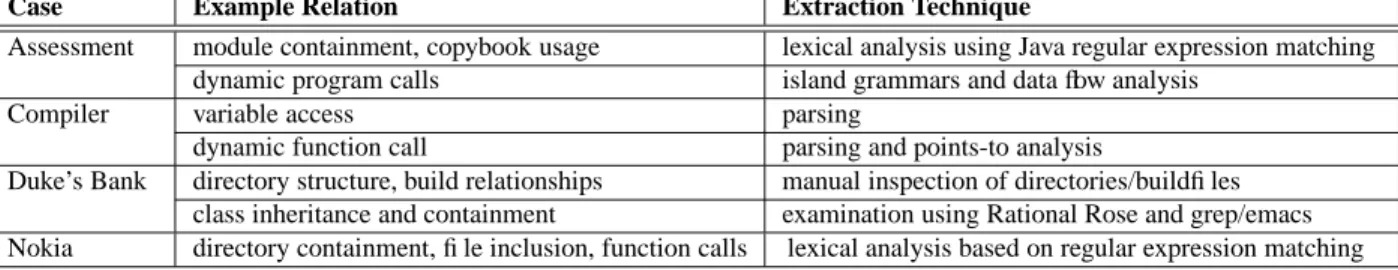
Examples. The types of data that we have gathered in the case studies are described in Figure 6. These facts are at a low level expressing knowledge in terms of source code elements (hence the term source views). In Knowledge In-ference these facts are abstracted (or lifted) to higher levels.
Techniques. Techniques for data gathering can be divided in static and dynamic analyses of the system. Static analyses analyze the system’s artifacts to obtain information that is valid for all possible executions (e.g, program structure or potential calls between different modules).
Dynamic analyses collect information about the system as it executes. The results of such an analysis are typically valid for the run in question, but no guarantees can be made for other runs. Dynamic analysis is done by tracing the exe-cution paths/profiles of the code and analyzing them for pat-terns, sequences, and dependencies. Such traces can be col-lected using code instrumentation, debugging, and profiling tools, or by connecting to a (prepared) runtime environment.
Note that these kinds of analyses do not necessarily have to be developed by the team that is using them to recover the architecture. Suitable results can be imported from a wide range of reverse engineering tools (such as clustering tools, data flow analysis tools, etc.). In practice, often a pragmatic mix-and-match approach for data gathering is applied, com-bining the results from various extraction tools using script-ing and gluescript-ing, for example, based on UNIXutilities such asjoin,split,awkandperl.
Below, we will look a little further into methods for ex-tracting facts from textual artifacts such as program code, buildfiles, etc. since that is the most used technique for data gathering. For a more detailed discussion of various meth-ods for source model extraction, we refer to the related work described in [24].
Manual Inspection. Our experiences show that some of
the data needed for a reconstruction project can be easily gathered manually by: examining the directory structure, ob-serving the behavior, or by exploring the source code for bea-cons that signal aspects of interest [25]. In our cases, this in-cluded for example the package structure and build relations for Duke’s Bank and the verification of client-server separa-tion in the Assessment case.
Lexical Analysis. Several tools are available that perform
lexical analysis of textual files. The most well-known is probablygrepthat searches text for strings matching a reg-ular expression. Tools likegrepgenerally give little support to process the matched strings, they just print matching lines. Such support is available in more advanced text processing languages such asawk,perl, andlexthat allow one to ex-ecute certain actions when a specific expression is matched.
The Lexical Source Model Extractor (LSME) uses a set
of hierarchically related regular expressions to describe lan-guage constructs that have to be mapped to the source view [26]. Use of hierarchical patterns avoids some of the pitfalls of plain lexical patterns but maintains the flexibility and robustness of that approach.
In our case studies, data gathering based on grepand
perl scripting was used for the Nokia case, parts of the
Assessment case and parts of the Duke’s Bank case.
Syntactic Analysis. Parser based approaches are used to
increase the accuracy and level of detail that can be ex-pressed. These typically create a syntax tree of the input and allow the users to traverse, query, or match the tree to look for certain patterns. This relieves them from having to han-dle all aspects of a language and focus on interesting parts. The Compiler case study uses syntactical analysis (extended with semantical analysis described below).
Fuzzy parsing. Fuzzy parsers are parsers that are able to
discard tokens and recognize only certain parts of a program-ming language [19]. This can be seen as a hybrid between lexical and syntactical analysis. These fuzzy parsers are hand crafted to perform a specific task. They focus mainly on
Case Example Relation Extraction Technique
Assessment module containment, copybook usage lexical analysis using Java regular expression matching dynamic program calls island grammars and data flow analysis
Compiler variable access parsing
dynamic function call parsing and points-to analysis
Duke’s Bank directory structure, build relationships manual inspection of directories/buildfiles class inheritance and containment examination using Rational Rose and grep/emacs Nokia directory containment, file inclusion, function calls lexical analysis based on regular expression matching
Figure 6. Some examples of the various data gathering techniques used in the cases.
parsingCandC++ to support program browsing. Typically
this involves extracting information regarding references to a symbol, global definitions, functions calls, file includes, etc.
Island Grammars. Island grammars are a novel technique
that can be used to generate robust parsers from grammar definitions [24]. Island grammars combine the detailed spec-ification possibilities of grammars with the liberal behavior of lexical approaches. The robust parsers generated from is-land grammars combine the accuracy of syntactical analysis with the speed, flexibility, and tolerance usually only found in lexical analysis. This makes this approach very suitable for developing source model extractors, even if the resulting extractor is used only for a single project. The DocGen docu-mentation generator used in our Assessment case uses island grammars for data gathering [6].
Semantical Analysis. Additional techniques such as name
and type resolution, data flow analysis and points-to analysis can be used to improve the results from other analyses (gen-erally on a syntactical basis). For example, in our Compiler case study, points-to analysis was used to determine more ac-curate call graphs than could be retrieved from just applying syntactical analysis. In the Assessment case study, a simple form of data flow analysis was used to trace program calls via a dynamic call handler.
Output. The output of the data gathering stage is a popu-lated repository containing the extracted source views.
6.2.
Knowledge Inference
Intent. The goal of the Knowledge Inference step is to de-rive the target view from the source view (typically a large relational data set describing the implementation of the sys-tem). The reconstructor creates the target view by condens-ing the low-level details of the source view and abstract-ing them into architectural information. The mappabstract-ing rules and domain knowledge are used to define a map between the source and target view. For example, if the mapping contains a rule about using naming conventions to combine classes into modules, the resulting map lists each class and the module to which it belongs. This activity may require either interviewing the system experts in order to formal-ize architecturally-relevant aspects not available in the im-plementation or to iteratively augment the source view by adding new concepts to the source viewpoint.
Depending on the degree of formalization of the mapping, this step can be fully or partly automated. We expect the Knowledge Inference step to be conducted initially in close cooperation with the system experts and, as more domain knowledge becomes formalized, more automation is added. This step can be summarized in the following activities: (1) create the map (containing the domain knowledge), and (2) combine the source view with the map to produce the target view. In practice, the map is often created iteratively, with each iteration refining the map or raising its level of abstrac-tion until it can produce a satisfactory target view.
Techniques. Existing techniques can be categorized as manual, automatic, or semi-automatic. Manual approaches typically use simple, general-purpose tools and manual in-spection of the system. While they may use reconstruction-specific tools such as SHRiMP, Rigi, PBS, and Bauhaus to help visualize intermediate results, there is no automated support for the process (see for example [22]).
Semi-automatic approaches help the reconstructor create architectural views in an interactive or formal way. They typically rely on the manual definition of the map. Differ-ences among the approaches concern the expressiveness of the language used for defining the transformations, support for calculating transitive closures of relations, degree of re-peatability of the process, amount of interaction required by the user, and the types of architectural views that can be gen-erated.
Relational algebra approaches allow the reconstructor to define a repeatable set of transformations for creating a par-ticular architectural view. In the work of Holt et al. [15] rela-tional algebra is used for creating a hierarchical module view of the source code (by grouping source files into modules and calculating the module dependencies). The reconstruc-tor must manually prepare the containment relations, but new relationships can also be inferred using algebra propositions. Postma [28] uses relational partition algebra (RPA) [10] to calculate module dependencies from dependencies extracted from code. RPA is also used to check the conformance of an extracted target view with a hypothetical view (established in the design phase). The process is repeatable and is part of the build process. Riva has proposed a method for infer-ring the architectural information based on relational algebra and Prolog [29]. Mens [23] uses logic meta programming
(Prolog) for mapping implementation artifacts to high-level design and for checking conformance of architectural rules.
More light-weight examples are the Reflexion
Model [27], Tcl scripts for defining graph transforma-tions in Rigi, SQL queries for defining grouping rules (Dali), or the ad-hoc graph query language (GReQL) of GUPRO.
Fully automatic approaches are based on different kinds of clustering algorithms: coupling, file names, concept anal-ysis, type inference.
All the case studies fall into the category of semi-automated approaches. The map between source view and target view was created manually. The map bridged the gap between conceptually different entities (e.g., source entities versus logical component and connectors in the Duke’s bank case) or concrete and hypothesized elements in the source and target views (e.g., the mapping of concrete modules onto hypothesized modules in the reflexion method for the Com-piler case). The manual map, then, allowed to propagate and lift relations between source entities to entities in the target view automatically.
For the creation of the map, technological, organizational, and often historical background knowledge as well as do-main knowledge is required. For instance, the Duke’s Bank case leveraged knowledge of web applications, the J2EE in-frastructure, and recommended design patterns. J2EE types provided information about which file executes in which container and which classes are separate components. De-sign patterns helped identify data-transfer classes and helper classes. The application functionality guided decisions about creating interfaces, combining classes into modules, and de-termining connectors.
The mapping is often difficult because of hidden depen-dencies. One interesting experience in the Duke’s Bank case, for instance, was the identification of “logical” or “hidden” interfaces. These were not explicitly visible in the source code and were discovered only by studying the control flow of the application and data sharing between classes that had no explicit dependencies. Obviously, the quality of the data gathering is key to a successful knowledge inference. The realization of poor data quality forces us to reiterate the data gathering with different means.
Output. The output is an enriched and structured reposi-tory where the source view and the domain knowledge has been combined to create the target view.
6.3.
Information Interpretation
Intent. The target views—selected to address a particular problem—are inspected, interpreted, and eventually applied to solve the problem. To these ends, the target views need to be made accessible both physically and mentally to all stakeholders.
Motivation. The views that result from Knowledge Infer-ence are not the answer to the problem but provide a
foun-dation to address the problem. In the Information Interpre-tation, conclusions are drawn from the reconstructed views. These conclusions then lead to measures to be taken to rem-edy the problem. (The measures themselves are not part of the reconstruction process.)
Ideally, the viewpoints were selected to allow an imme-diate use of the views; however, even if the viewpoints are carefully tailored, it might become difficult to get an answer at the level of the target views because they may span a huge information space. In such cases, presentations are required that make this information space amenable to all stakehold-ers. The presentation must be readable and traceable. Read-ability relates to the Read-ability to easily find and grasp relevant information in the views; traceability allows us to trace the inferred knowledge back to the original data.
Techniques. The scope of the presentation (i.e., the arti-facts and their aspects to be presented) is already given in form of the selected viewpoints and target views. The view-ers and task to be achieved are stated in the Problem Elicita-tion. We focus on presentation and interaction issues here.
Although the selected viewpoints define the vocabulary and semantics for the representation, they do not define how
to present the information. Information presentation
ad-dresses this problem, where we take presentation quite lib-erally: any means to communicate information to a viewer, be it textually, graphically, or through other forms of human perception including any form of interaction with the pre-sentation. Sight is the most often addressed form of human perception by information presentation in the software archi-tecture domain; that is why we are using the narrower term
visualization instead of perception in the following.
Presentation issues have to do with effective visual com-munication including the visual vocabulary, the use of the specific visual elements to convey particular kinds of infor-mation, the organization of visual inforinfor-mation, and the order in which material is presented to the viewer. Most applica-tion domains have their own convenapplica-tions and symbology that should be used for the visual vocabulary and elements.
Due to lack of space, we refer the reader to overviews on software visualization in the literature [33, 18, 2]. Yet, at least we want to point out that graphs seem to be a ”nat-ural” visualization of architecture elements and their (often binary) relations, as confirmed by independent surveys that indicate their popularity [2, 20] (in the end, class and object diagrams in UML are just graphs with predefined semantics and rendering characteristics). In the Compiler, Assessment, and Nokia case studies, graphs were used to convey the in-formation.
The aspect of interaction refers to the way the visualiza-tion is constructed. Visualizavisualiza-tions range from ”hard-wired”, where the viewer has no influence on the presentation, to ar-bitrary redefinition by the viewer. Visualizations should not be static pictures, but should offer querying, zooming in and
out, navigation along cross-references and hierarchies, selec-tive hiding, and gathering of transiselec-tive relations.
Some of the case studies used ”‘standard”’ elements, such as hyperlinked HTML or PDF documents with embedded UML diagrams (the Nokia and Assessment cases). UML was also used in the Duke’s Bank case, but here the dia-grams were crafted manually. Simple types of visualization, namely, textual ones and tables, were also used where ap-propriate (e.g., the Assessment case used tables for metrics). The Nokia, Assessment, and Compiler cases used navigat-able visualizations with zooming and filtering capabilities.
We believe that all case studies could have benefited from more advanced and carefully selected means of visualiza-tion. Visualization issues were brought up as an afterthought and, hence, the potential of visualization was only partially leveraged. The reason for this shortcoming is simply that the means of presentation chosen in the case studies were mostly opportunistically selected from available tools. The focus in these cases was to solve the problem quickly with available tools. As the initial processes are repeated more often, we expect that their maturity will improve by a more careful consideration of presentation issues.
A particular problem of software architecture is the need to understand a combination of multiple views, which is fur-ther complicated when the views are of conceptually differ-ent viewpoints. There have been several suggestions to the ”view fusion” problem. If the views overlap in some of their entities, one can use certain inferences to map entities with no immediate correspondence to entities in the other view. For instance, Kazman and Carri`ere use ”lifting” operations along containment relations to fuse views [17]. If the entities may be mapped onto source code, one could leverage over-lapping source code regions to identify correspondencies be-tween entities [3]. If there is no such simple correspon-dence, the mapping is typically manual. Hillard, Rice, and Schwarm [13], for instance, systematically cross reference related entities from distinct views and use Ross’s model tie process from Structured Analysis to integrate the views [30]. These cross-references are created as part of Symphony’s Knowledge Inference in the form of the maps and stored so that the connection among views is made explicit. The cross-references may be implemented and inserted into the views by available frameworks [1, 8]. Multiple views occured in all case studies (in the Compiler case, the mapping and the de-pendencies propagated from the source to the target entities were also visualized).
Output. The output of the Information Interpretation is a hyperstructure offering a holistic perspective on the software system as a foundation for investigating the concrete archi-tecture’s impact on the problems signaled. This hyperstruc-ture includes traceability links between views and links to other software artifacts, such as the source text, relevant doc-umentation, etc. The ideal hyperstructure allows you to
ex-plore the system at various levels of abstraction: it lets you zoom in and zoom out between sources and architecture and navigate between views.
7.
Concluding Remarks
In this paper we have presented Symphony, a software archi-tecture reconstruction process that: (1) incorporates the state of the practice, where reconstruction is problem-driven and uses a rich set of architecture views; (2) provides guidance for performing reconstruction, including pointers to appli-cable technology; (3) allows specific reconstructions to be systematically compared; and (4) allows reconstruction ap-proaches to be systematically compared.
Symphony consists of two stages. The first stage (Prob-lem Elicitation and Concept Determination) produces a re-peatable and reusable reconstruction strategy that creates the views necessary to address the original problem. Although not an ultimate goal, the problem-dependent viewpoints cre-ated or refined in the Concept Determination phase are an-other reusable output of this stage.
The second stage of Symphony concerns the execution of the reconstruction strategy. This stage operates only at the level of views constrained by the viewpoints created before. Their outcome is the foundation for addressing the problem for which the particular reconstruction is carried out. A sec-ondary outcome is the sequence of mappings from the source views to the target views. This sequence allows one to trace back the information in the views to the artifacts from which they were derived.
This paper also shares real-life reconstruction experience by presenting and comparing different case studies. Recon-struction in practice is problem-driven, using not a fixed set of views but ones chosen to solve the particular problem. The viewpoints used in practice are not confined to the Module viewpoint typically used in the research literature.
Viewpoint selection and definition is an important part of the Symphony process. Using viewpoints to specify the input and output of an activity allows us to decompose the recon-struction process systematically and to review the outcome of each activity. In addition, we can reuse an activity—once defined and used for a reconstruction process—as a building block to compose new reconstruction processes.
Symphony has been applied in academic and industrial case studies and unifies other existing reconstruction tech-niques and methods. The process model described in this paper allows readers to leverage from that experience when setting up their own architecture reconstruction efforts. We provide a step-by-step methodology that can be followed and give pointers for the selection of appropriate techniques and methods for each of the phases.
In addition, Symphony provides a common reference framework that can be used when classifying and
compar-ing various techniques and methods described in the litera-ture. Such a common reference also helps people to report on their own reconstruction efforts in a uniform way so that others can easily understand it.
Last but not least, Symphony is a research tool: it helps us to find and demarcate research problems in software archi-tecture reconstruction. For example, Symphony’s viewpoint emphasis calls for a catalog of reconstruction methods, tech-niques, and experiences organized by viewpoints. Moreover, it raises the question what reconstruction-specific viewpoints exist. Symphony’s inclusion of mappings between source and target views suggests finding a systematic way to dis-cover and describe such mappings as a key research question. Problems like these are hard to tackle. Symphony makes it possible to address them on a case-by-case basis, offering its process model as a way to classify and compare results.
Acknowledgements Arie van Deursen and Leon Moonen re-ceived partial support from ITEA (Delft University of Technology, project MOOSE, ITEA 01002), and SENTER (CWI, project IDE-ALS, hosted by the Embedded Systems Institute).
References
[1] K. M. Anderson, R. N. Taylor, and E. J. Whitehead Jr. Chimera: hy-pertext for heterogeneous software environments. In Proc. European
conference on Hypermedia technology. ACM, 1994.
[2] S. Bassil and R. K. Keller. Software visualization tools: Survey and analysis. In Proc. Int. Workshop on Program Comprehension (IWPC), pages 7–17. IEEE CS, May 2001.
[3] M. P. Chase, D. Harris, and A. Yeh. Manipulating recovered soft-ware architecture views. In Proc. Int. Conf. on Softsoft-ware Engineering
(ICSE), pages 184–194. ACM, 1997.
[4] P. Clements, F. Bachmann, L. Bass, D. Garlan, J. Ivers, R. Little, R. Nord, and J. Stafford. Documenting Software Architectures: Views
and Beyond. Addison-Wesley, 2002.
[5] A. van Deursen, C. Hofmeister, R. Koschke, L. Moonen, and C. Riva. Symphony: View-driven software architecture reconstruction. Techni-cal Report SEN-R0404, CWI, 2004. Available fromhttp://www.
cwi.nl/ftp/CWIreports/SEN/SEN-R0404.pdf.
[6] A. van Deursen and T. Kuipers. Building documentation generators. In Proc. Int. Conf. on Software Maintenance (ICSM), pages 40–49. IEEE CS, 1999.
[7] A. van Deursen and T. Kuipers. Source-based software risk assess-ment. In Proc. Int. Conf. on Software Maintenance (ICSM). IEEE CS, 2003.
[8] P. Devanbu, R. Chen, E. Gansner, H. M ¨uller, and A. Martin. Chime: Customizable hyperlink insertion and maintenance engine for soft-ware engineering environments. In Proc. Int. Conf. on Softsoft-ware
Engi-neering (ICSE). ACM, 1999.
[9] L. Ding and N. Medvidovic. A light-weight, incremental approach to software architecture recovery and evolution. In Proc. Working Conf.
on Software Architecture (WICSA), pages 191–200. IEEE CS, 2001.
[10] L. Feijs, R. Krikhaar, and R. van Ommering. A relational approach to support software architecture analysis. Software Practice and
Experi-ence, 28(4):371–400, 1998.
[11] P. J. Finnigan, R. C. Holt, I. Kalas I, S. Kerr, K. Kontogiannis, H. A. M ¨uller, J. Mylopoulos, S. G. Perelgut, M. Stanley, and K. Wong. The software bookshelf. IBM Systems Journal, 36(4):564–593, Oct. 1997.
[12] G. Y. Guo, J. M. Atlee, and R. Kazman R. A software architecture re-construction method. In Proc. Working Conf. on Software Architecture
(WICSA), pages 15–33, 1999.
[13] R. F. Hillard II, T. B. Rice, and S. C. Schwarm. The architectural metaphor as foundation for system engineering. In Proc. Ann. Symp.
of the Int. Council on Systems Engineering, 1995.
[14] C. Hofmeister, R. Nord, and D. Soni. Applied Software Architecture. Object Technology Series. Addison Wesley, 2000.
[15] R. C. Holt. Structural manipulations of software architecture using tarski relational algebra. In Proc. Working Conf. on Reverse
Engi-neering (WCRE), 1998.
[16] IEEE P1471-2000. IEEE recommended practice for architectural de-scription of software-intensive systems, 2000.
[17] R. Kazman and S.J. Carri`ere. View extraction and view fusion in archi-tectural understanding. In Proc. Int. Conf. on Software Reuse (ICSR), 1998.
[18] C. Knight and M. Munro. Mediating diverse visualisations for com-prehension. In Proc. Int. Workshop on Program Comprehension
(IWPC), pages 18–25. IEEE CS, May 2001.
[19] R. Koppler. A systematic approach to fuzzy parsing. Software Practice
and Experience, 27(6):637–649, 1997.
[20] R. Koschke. Software visualization in software maintenance, reverse engineering, and reengineering: A research survey. Journal on
Soft-ware Maintenance and Evolution, 15(2):87–109, 2003.
[21] R. Koschke and D. Simon. Hierarchical reflexion models. In Proc.
Working Conf. on Reverse Engineering (WCRE). IEEE CS, Nov. 2003.
[22] P. K. Laine. The role of sw architectures in solving fundamental prob-lems in object-oriented development of large embedded sw systems. In Proc. Working Conf. on Software Architecture (WICSA), 2001. [23] K. Mens. Automating architectural conformance checking by means
of logic meta programming. PhD thesis, Departement Informatica,
Vrije Universiteit Brussel, 2000.
[24] L. Moonen. Generating robust parsers using island grammars. In Proc.
Working Conf. on Reverse Engineering (WCRE), pages 13–22. IEEE
CS, Oct. 2001.
[25] L. Moonen. Exploring Software Systems. PhD thesis, Faculty of Natu-ral Sciences, Mathematics, and Computer Science, University of Am-sterdam, Dec. 2002.
[26] G. C. Murphy and D. Notkin. Lightweight lexical source model ex-traction. ACM Transactions on Software Engineering and
Methodol-ogy, 5(3):262–292, July 1996.
[27] G. C. Murphy, D. Notkin, and K. J. Sullivan. Software reflexion mod-els: Bridging the gap between design and implementation. IEEE CS
Transactions on Software Engineering, 27(4):364–380, Apr. 2001.
[28] A. Postma. A method for module architecture verification and its ap-plication on a large component-based system. Information and
Soft-ware Technology, 45:171–194, 2003.
[29] C. Riva. Architecture reconstruction in practice. In Proc. Working
Conf. on Software Architecture (WICSA), 2002.
[30] D. T. Ross. Removing the limitations of natural languages (with the principles behind the RSA language). In Proc. the Software
Engineer-ing Workshop. Academic Press, 1980.
[31] C. Stoermer, L. O’Brien, and C. Verhoef. Practice patterns for archi-tecture reconstruction. In Proc. Working Conf. on Reverse Engineering
(WCRE). IEEE CS, 2002.
[32] S. Tilley, S. Paul, and D. B. Smith. Towards a framework for program understanding. In Proc. Int. Workshop on Program Comprehension
(IWPC), pages 19–28. IEEE CS, 1996.
[33] M. Wiggins. An overview of program visualization tools and systems. In Proc. 36th Annual Southeast Regional Conf., pages 194–200. ACM, 1998.