306
© Global Society of Scientific Research and Researchers
http://asrjetsjournal.org/
Vision-Based Mobile Robot Self-localization and Mapping
System for Indoor Environment
Lei Lei Tun Shwe
a*, Wut Yi Win
baPh. D Candidate, Department of Mechatronics Engineering, Mandalay Technological University, Myanmar bProfessor and Head, Department of Mechatronics Engineering, Mandalay Technological University, Myanmar
aEmail:[email protected] bEmail: [email protected]
Abstract
Localizing accurately and building map of an environment concurrently is a key factor of a mobile robot system. In this system, the robot makes localization and mapping with artificial landmarks and map-based system. It is a process by which a mobile robot can build a map of an environment while continuously determining the location of the robot within the map. The system estimates the robot position in indoor environments using sensors; a camera, three ultrasonic sensors and encoders. The main contribution of this paper is to reduce computational time and improve mapping with map-based system. The self-localization of mobile robot in an indoor environment is advanced through the construction of map based on sensors and recognition of artificial landmarks. Vision based localization system can benefit from using with ultrasonic sensors. From captured images, the system makes landmark detection by using Canny edge detection and Chain-code Approximation algorithms to represent the contour of landmarks by using edge points. The Kalman filter is aimed to accurately estimate position and orientation of the robot using relative distances to walls or artificial landmarks in environments. A robotic system is capable of mapping in an indoor environment and localizing with respect to the map, in real time, using artificial landmarks and sensors.
Keywords: Artificial landmarks; Canny edge detection; Camera; Kalman filter; Encoders; Localization; Mapping.
--- * Corresponding author.
307
1.Introduction
Autonomous navigation is an important ability for mobile robots. Unlike traditional industrial robotic systems which are made up of linked manipulators and are fixed to one physical location. Mobile robots have the capability to move around in their environment and are not fixed to one physical location. The process of concurrently estimating the position of a mobile robot relative to its environment and building a map of the environment, has been a fundamental research for the past few years. Mobile robots are capable of interacting with their different environments autonomously [1]. They are structured indoor environments and unstructured outdoor environments. This system is intended to use in indoor environment. The self-localization of mobile robots in a structured indoor environment is advanced through the construction of map. Obtaining navigation information from GPS is hard for mobile robot if it is in indoor environments. There are not enough visible GPS satellites in there. For this cases, vision-based self-localization and mapping method can be used for navigation system.
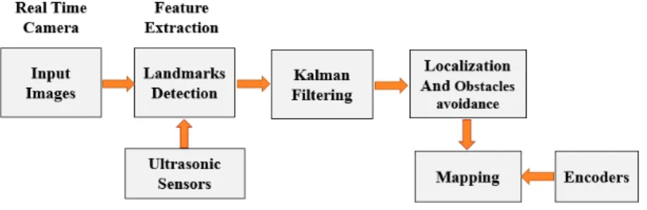
There are various kinds of sensors for localization and mapping. For example, laser range finder, ultrasonic sensor, vision sensor, etc. In this system, a vision sensor, three ultrasonic sensors and encoders are used to provide more precise position and heading information for localization and mapping. Camera is used for getting data to make artificial landmarks detection that can be along the robot moving way in indoor environment. And three ultrasonic sensors are used for wall and obstacles detection to prevent from collision while making localization and also to get the distance between the robot and the landmark. To count the number of revolutions of each wheel, the robot measures the distance it has travelled and its heading direction by using wheel encoders. In this work, three ultrasonic sensors and a camera were combined to provide a sensor system for a mobile robot. These two types of data have their advantages and are very often used in robotic applications, but combining them provides even more useful information. The position estimation based on data from only one sensor is often not reliable enough to solve the localization and mapping problems [2]. So, the multi-sensor data fusion has received much attention recently due to its ability to combine advantages of each sensor type to extract more accurate information. Sensor data are used to compute the robot pose and to construct the map. The system block diagram is shown in Figure.1.
Figure 1: System Block Diagram
In an indoor environment, the mobile robot is moving and captures the images. From the starting point, the robot localizes its position and draws map using the data from encoders and ultrasonic sensors. If the robot found landmark on the front wall by using camera, the front ultrasonic sensor will detect the distance between
308
landmark and robot. If the system gets distance (100 ~ 120cm) from front ultrasonic sensor, it will make landmark detection by using the data from camera. The system will detect only the artificial landmark which is in front of the robot in the environment. After landmark detection, the robot makes pose estimation. While estimating the position of the robot, accurate pose estimation couldn’t be got because of the errors in localization system. An accurate solution of the localization and mapping problem is important for navigation system so Kalman filter (KF) is used. Kalman filter is widely used for localization and mapping system. Kalman filters solve uncertainties in robot localization, navigation, following, tracking, motion control, estimation and prediction. Kalman Filter utilizes the data between observed and detection of artificial landmarks, to correct the position and orientation of the robot. The exploration of an indoor environment by mobile robot is a challenging problem. For self-localization, the robot also requires a map, but to build a map, the pose of the robot must be known. This research is developed in the situation of map-based autonomous navigation framework. Map-based navigation considers that the navigation system is provided with some previous model of the environment, also called a map. The map-based autonomous navigation framework considered in this paper.
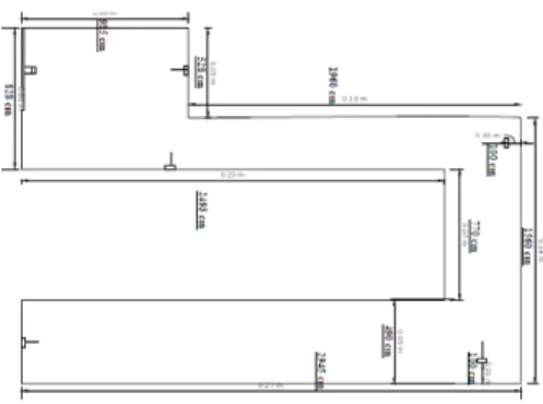
Figure 2: Plan View and landmarks placements in indoor environment
The plan view of the indoor environment and the artificial landmarks that are placed in the way of the environment are shown in Figure.2. In Figure.2, artificial landmarks are denoted by rectangle symbols on the walls. In this paper, indoor robot localization and mapping system is introduced in Section 1. In Section 2, the system related works are discussed. The system modelling is described in Section 3. In Section 4, the proposed system for localization and mapping system. Experimental results to get the accuracy of robot localization and mapping using the sensor readings are presented in Section 5. The paper concludes in Section 6.
2.Related Works
Self-localization and Mapping is an important skill for autonomous mobile system. The aim of this system is the estimation of the robot’s pose and building map in an indoor environment. Over the last decade, a vast number of localization and mapping system have appeared. The problem of localization has a rich history in the mobile robotics literature and several localization strategies have been developed using several kinds of sensors (e.g. laser scanners, sonars, cameras). This information is essential for the robot to safely interact within its environment. Most of the early works use a laser rangefinder, encoders, infrared and ultrasonic sensors [3, 14, 15]. More recently, visual sensors have become popular in this work. They can be used in both indoor and outdoor environments. These characteristics make cameras an ideal choice for multi-purpose mobile robotic
309
platforms. The idea behind this work is to extend the state of a Kalman filter used for localization with the kinematic parameters of the wheel encoders. Whereas this approach can operate on-line, it requires a-priori known map. Subsequently, Jones and his colleagues and Kelly and his colleagues extended the EKF and UKF algorithm to include calibration parameters. In the past, several approaches [13,16], to tackle the data association problem have been developed. Whereas highly effective methods for computing a map given the data associations have been developed in the past [5-6, 17-19], the development of methods for robust data association is still an open research problem. One way of resolving uncertainty in the environment and supporting data association is to use artificial landmarks. Inherently uncertain environments make these localization approaches more likely to fail.
Utilizing artificial landmarks offers the possibility of improving the reliability of the localization. Some approaches [7-8, 20-23] consider artificial landmarks that can be uniquely identified. In this research, visual pattern landmarks are used to reduce uncertainty for localization and mapping. A break-through in the research on environment modelling for autonomous mobile robots was the formulation of the mapping and self-localization problems, which were formerly considered separately, as a single estimation problem. In this research, the robot estimates its position with map-based autonomous navigation framework to handle the localization problems. This system is able to reduce uncertainty for localization and a pose estimation scheme and simultaneously builds the map of the environment. Special preparation for the environment, artificial landmarks placement, is required. Simple artificial landmark models show invariant characteristics in cluttered environments.
3.System Modeling
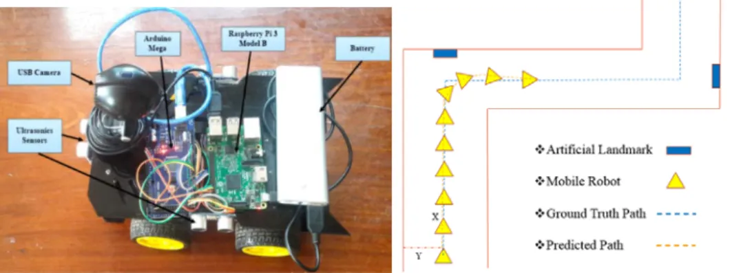
In this research, a simple mobile robot platform has a vision sensor, three ultrasonic sensors and two encoders. When vision sensor obtains images continuously, the system detects landmarks and obstacles in the environment by using with the data from ultrasonic sensors. The encoders are equipped on wheels and provide wheel rotation data. There are various kinds of errors; wheel radius error, wheel distance error, slips error, conversion factor error, etc. In this system, the localization errors are reduced by using Kalman filter and sensor data fusion system. The mobile robot equipped with sensor system is shown in Figure.3.
Figure 3: Mobile robot equipped with sensor system
310
Landmarks are the defined objects in the environment that provide more localization accuracy. To reduce the uncertainty in the environment, the mobile robot uses artificial landmarks for estimating the position. Artificial landmarks can be designed in order to be uniquely identified by the sensor.
Figure 4: Signs of Artificial Landmarks
Since artificial landmarks are supposed to simplify extraction of location features, the landmarks can be reliably detected and identified in a given environment. The artificial landmarks that are used in this research are shown in Figure.4.
3.2.Sensor Fusion with Vision and Ultrasonic sensors
The system uses vision sensor to detect the landmark signs. When the robot’s front ultrasonic sensor gets the distance which is within the assigned detection area, the system will make landmark detection by fusing with the data from vision sensor. Landmark detection are made with image processing techniques. While processing, ultrasonic sensors will detect walls and obstacles in the environment and then avoid effectively. Since the speed of the sound wave can know, the system can calculate the distance of the obstacles and landmark by using ultrasonic sensors.
Distance = speed x time (1)
The ultrasonic sensors have emission frequencies of 56 kHz. The sensors used in this work have a range of about 0.30 m to 10 m. Block diagram of the proposed sensor data fusion system is shown in Figure.5. The system obtains information of surrounding environments using its sensors and decides its way of action according to its programming and detection results. The system will make landmark detection by fusion the data of visual and ultrasonic sensors system by using image processing techniques. With sensor data fusion, the system can predict the position and obstacles in the environment effectively.
311
Figure 5: Block diagram of the sensor data fusion system
To make pose estimation, the system is necessary to find the region of interest (ROI) at the center of the detected artificial landmark in the coordinate frame fixed to a camera in the case of localization using the image captured by the camera.
Figure 6: View angle of the camera and landmark detection area of the ultrasonic sensor
Viewing angle of the camera and landmark detection area of the ultrasonic sensor is shown in Figure.6. When the robot found the landmark within the camera viewing angle (54 degree) and the front ultrasonic sensor detection range is between 90 and 120cm, the system will make landmark detection.
3.3.Landmark Detection System
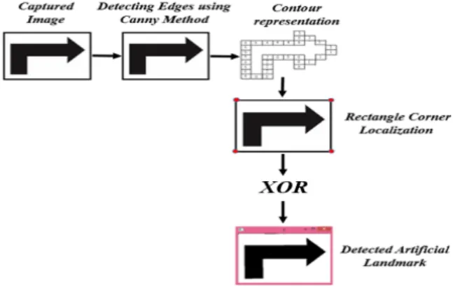
To estimate the location of the mobile robot, the system will have to make landmark detection. After landmark detection, the robot will know the way where to go and how to act. The image processing steps for landmark detection are shown in Figure.7.
Figure 7: Landmark detection steps
Each step of landmark detection algorithm is described below.
i. Thresholding
312
retain only the portions of the image that are white. So, the input color image is converted into the gray scale image and normalize the image adaptively. The thresholded image is used to predict the orientation of the landmark in the image.
ii. Detecting Edges using Canny Method
Canny edge detection is a process of locating an edge of an image. Detection of edges in an image is a very important step towards understanding image features. Edges consist of meaningful features and contain significant information. Processing results for Canny edge detection is shown in Figure.8. After making thresholding, the image is detected with Canny edge detection. In Canny edge detection algorithm, it is firstly smoothed the noise in the image by applying a Gaussian filter because all images taken from a camera will contain some amount of noise. Then, it finds the gradients of the landmark so that the edges should be marked where the gradients of the image has large magnitudes. It reduces the number of false edges by applying double thresholding. Final edges are determined by suppressing all edges that are not connected to a very certain (strong) edge.
Figure 8: Processing results for Canny edge detection
i. Contour representation using edge points
Chain-code approximation algorithm is used to represent the result edge points as contour of the landmark. Edges must be linked into a representation for a region boundary called contour. It starts at the first edge point and goes clockwise direction around the contour. The direction to the next edge point is specified using eight quantized directions. A contour may be represented as an ordered list of edges. The accuracy of the contour representation is determined by the accuracy of the estimates of edge location. Higher accuracy can be obtained by computing an approximation that is not forced to pass through particular edge points. Approximation-based methods use all the edge points to find a good fit. Processing results for Contour representation is shown in Figure.9.
313
Figure 9: Processing results for Contour representation
ii. Corner Localization
To recognize the landmarks whether it is or not, the robot have to find the four corners of the rectangle of the landmark that enclose the symbol. The robot finds four corners (Top left, Top right, Bottom left, and Bottom right) to be more sure the location of the landmark. Processing results for corner localization is shown in Figure.10.
Figure 10: Processing results for Corner localization
iii. Matching Landmarks with XOR
After corner localization, the system will match the detected artificial landmark with the predefined landmarks which are already stored in the system as database by using XOR function. Processing results for matching landmark using XOR is shown in Figure.11. After making the landmark detection processes, the system will get the detected artificial landmark and will show the sign of the landmark with words (e.g. Go, Turn Left, etc).
Figure 11: Processing results for matching landmark using XOR
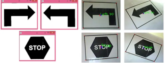
The results of the detected artificial landmarks are shown in Figure. 12(a). In this system, landmark detection method is applicable to mobile robot localization. It proved to achieve solutions with less computational times which provide detection more precisely whatever the landmark position and it only need to focus on the area which has landmark. The results of the detectable pictures of landmarks are shown in Figure. 12(b).
314
(a) (b)
Figure 12: (a) Results of the landmark detection with image processing techniques
(b) Detectable pictures of landmarks
3.4.Kalman Filtering System
In localization method, Kalman filter estimates the current position of the robot and also reduces the localization errors that are caused by sensors. The estimated probability distribution evolves according to Kalman Filter that updates the current position according to the new observations data from sensor system as they are gathered by the robot in successive time steps. At each time while localizing, KF calculates the best estimate of the state vector in two steps [25]:
i. The prediction step
In this step, the system predicts the current state based on the previous state and on the applied input signals
k k k k k
A
X
Bu
X
ˆ
| −1=
ˆ
−1|−1+
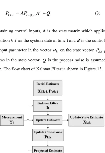
(2)Q
A
AP
P
k|k−1=
k−1|k−1 T+
(3)Where
u
kis the vector containing control inputs, A is the state matrix which applies the effect of each system state parameter at time transition k-1 on the system state at time t and 𝑩𝑩 is the control input matrix which applies the effect of each control input parameter in the vectoru
k on the state vector.P
k|k−1is the variances associated with the corresponding terms in the state vector. Q is the process noise is assumed to be drawn from normal distribution with covariance. The flow chart of Kalman Filter is shown in Figure.13.Initial Estimate Xk\k-1, Pk\k-1 Kalman Filter Jk Update Estimate Update Covariance Pk\k Measurement Yk
Update State Estimate
Xk\k
Projected Estimate
315
ii. The update step
This step uses system to correct the predicted state by verifying with the actual sensor measurements.
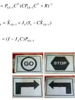
1 1 | 1 |
(
)
− − −+
=
P
C
CP
C
R
J
T k k T k k k (4))
ˆ
(
ˆ
ˆ
1 | 1 | |k=
kk−+
k k−
kk− kX
J
Y
C
X
X
(5) 1 | |k=
(
−
k)
kk− kI
J
C
P
P
(6)Figure 14: Processing results for Kalman filtering
The matrix
k
J is called the Kalman gain and the system calculates the Kalman gain from the errors in estimate and data measurement. Then, the current estimate,
k k
Xˆ | is calculated by the previous estimate and the
measurement value. After that new error in the estimate,
P
k|kis calculated to make next pose estimation. Whenthe robot can define the sign of the landmark, it will know where to go. Finally, it will make pose estimation to know the location of robot by using Kalman Filter. In Figure.14, red color cross shows the measurement value result from sensors and blue color cross describes the estimated value by calculating the result data with Kalman Filter.
3.5.Software System
The implementation of the localization and mapping system have been performed by OpenCV framework. The performance of this system was implemented on the Raspberry Pi. OpenCV is an open source computer vision library from Intel. It is intended for use by both commercial and non-commercial users including researchers, commercial software developers, governments and camera vendors. It consists of C functions which implement standard computer vision algorithms such as edge and corner detection and motion analysis. Other features include linear algebra and raw matrix support, windowing system and functions and data structures for reading and writing and images video streams. In this research, OpenCV is used for processing system by loading information from sensor system for extracting features while localizing and mapping.
316
The mobile robot has four drive wheels. These drive wheels are connected to DC motors and only two drive wheels are attached with wheel encoders. These encoders are capable of monitoring the revolutions and steering angles of the drive wheels. The main advantage offered by these encoders is their high resolution. The two output channels of the encoder indicate both position and direction of rotation. The distance travelled by the robot is the number of rotations times the wheel’s circumference. The wheel’s circumference is given by (2 * pi * r), where r is the wheel’s radius. The mobile robot will make localization and mapping with wheel revolutions when there is no landmark signs in the environment.
3.7.Robot Controlling System
In mobile robot control system, the system will make motor driving control after the position estimation data (i.e. x, y position and heading angle) are got from processing techniques by using with wheel encoders and ultrasonic sensors. In this states, the robot will go straight forward and simultaneously make localization and mapping by using these two sensors until it finds the artificial landmark. When it found landmark, it will make image processing for detecting landmark by using with camera and ultrasonic sensors. When it gets the matching results (i.e. the name of detected landmark sign) from landmark detection process and has assigned detection distance range of front ultrasonic sensor, the system will send the result data to Arduino control board for motor driving control. Motor driving system for localization and mapping is shown below:
1. Start
2. Detect Artificial Landmark
3. IF GO Sign Landmark and Front Distance is 90 ~ 120 4. THEN Mobile Robot moves forward
5. UNTIL Next Landmark detect
6. IF TURN LEFT Sign Landmark and Front Distance is 90 ~ 120 7. THEN Mobile Robot turns left
8. AND THEN moves straight forward 9. UNTIL Next Landmark detect
10. IF TURN RIGHT Sign Landmark and Front Distance is 90 ~ 120 11. THEN Mobile Robot turns right
12. AND THEN moves straight forward 13. UNTIL Next Landmark detect
14. IF STOP Sign Landmark and Front Distance is 90 ~ 120 15. THEN Mobile Robot stops
16. END
4.Proposed System for Localization and Mapping
In robot localization problem, the robot has to find out its location relative to the environment. To know the location pose or position of the robot, the x and y coordinates and heading direction need to be estimated. For properly initializing the navigation system, as accurate solution of the localization problem is important, Kalman
317
filter is used. The mobile robot and its sample localization and mapping system are shown in Figure.15. In this localization system, the mobile robot makes self-localization by using the data from encoders and ultrasonic sensors unless there is artificial landmarks in the environment. From starting point, the robot will know x, y position and heading information. The system will estimate the position of the robot by calculating the data of wheel revolutions from encoders and ultrasonic sensors with Kalman filter. So, the system can estimate the position more accurately and can avoid the obstacles effectively.
(a) (b)
Figure 15: (a) Mobile Robot and
(b) Sample Mobile Robot Localization and Mapping System
When the robot found the landmark, it will make landmark detection by fusing the data from camera and ultrasonic sensors. After that, the robot will know where to go and how to act. After moving by reading with the sign of the detected landmark, the robot will go straight until it finds next landmark by localizing with wheel encoders and ultrasonic sensors. The localization techniques need a map of the environment in which the robot operates for localization. In order to autonomously build a map of an environment, the robot must know where it is within the environment (localize itself). So as to achieve this, the robot must concurrently localize itself and build a map of the environment. In this research, the mobile robot is intended to use in a structured indoor environment. So, the robot made self-localization and mapping by map-based system.
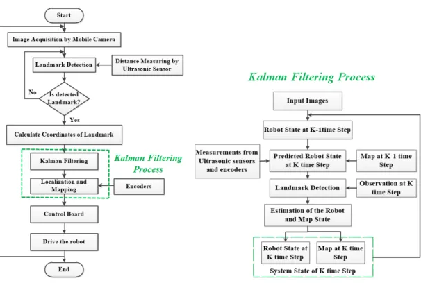
4.1.System Flow Chart for Localization and Mapping
For mobile robot self-localization and mapping, step-by-step system working flow is shown in Figure. 16(a). Firstly, the mobile robot captures the images from camera and then it makes landmark detection to decide if it is landmark or not. If there is artificial landmark on the robot’s front wall, the system will make landmark detection by fusing the data with vision sensor and ultrasonic sensor and then will get x and y coordinates from detection process. After that these data are sent to Kalman filter to estimate the position of the mobile robot. The robot can make localization more accurately by calculating the received data with Kalman Filter. In Kalman filtering process, the system predicts the robot state at K time step by using the data of the robot’s state and map at K-1 time step and measurement values from Ultrasonic sensors and wheel encoders. From observation
318
landmarks at K time step, the system makes estimation of the robot and the map state.
(a) (b)
Figure 16: (a) System Flow chart and (b) Flowchart of Kalman filtering process for Localization and Mapping
Then, the system updates the current state (K time step) of the robot and continuously makes mapping. When the robot knows its position, the data are sent to the control board to drive the motor. Then, the robot moves forward around in the structured indoor environment by making localizing and mapping simultaneously.
5.Tests and Results for Localization and Mapping
The implementation of the landmark detection algorithm and localization system have been performed by OpenCV framework. The performance of this system was implemented on the Raspberry Pi. In the detection phase, the landmark samples are acquired by a camera mounted on a vehicle. The mobile robot extracts the features of the proposed landmarks by using the landmark detection algorithms.
5.1.Experimental Results for Localization System
Artificial landmark-based localization algorithm is proposed to localize the mobile robot in indoor environment. The system will detect only the landmarks which is on the front wall of the robot in the environment. If the system gets distance between robot and landmark (100 ~ 120cm) from front ultrasonic sensor, it will make landmark detection by fusing with the data from camera.
319
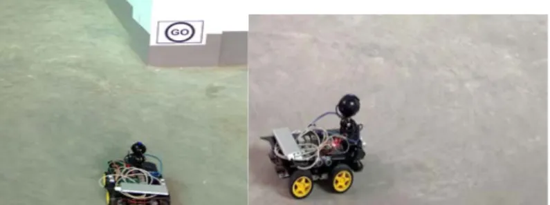
which are directed. When the robot knows its way where to go, it will go straight forward until it finds next landmark. Detecting Go sign landmark is shown in Figure 17.
Figure 17: Detect Go Sign landmark and move
Figure 18: Detect Turn Right Sign landmark and turn
When the robot knows its way where to go, it will detect nothing for a while until it finds next landmark, except obstacle and wall detection. The robot moving and working process of turning right and left are shown in Figure.18 and 19.
Figure 19: Detect Turn Right Sign landmark and turn
The stop sign detection process of mobile robot is shown in Figure.20. The system can reduce computational time because it only need to focus on the probable area which has landmark.
320
The results of the mobile robot self-localization system by reducing position errors are shown in the Table 1. The experimental results have confirmed the capability and performance of the system. The results of applying sensor fusion can reduce the localization errors in indoor environment efficiently.
Table 1: Localization error between measurement and Kalman calculated values
Measurement Value Kalman Value Error (%)
X Y X Y X Y 28.0 19.0 22.5 15.6 24.4 21.8 28.9 18.2 26.1 20.2 2.9 9.9 29.6 18.9 30.6 17.9 10.7 5.6 30.5 18.7 31.4 19.3 3.3 3.1 30.2 17.9 31.0 17.7 2.6 1.2 30.9 17.5 30.6 17.4 1.0 0.6 30.4 17.4 30.3 17.3 0.3 0.5
5.2.Experimental Results for Mapping System
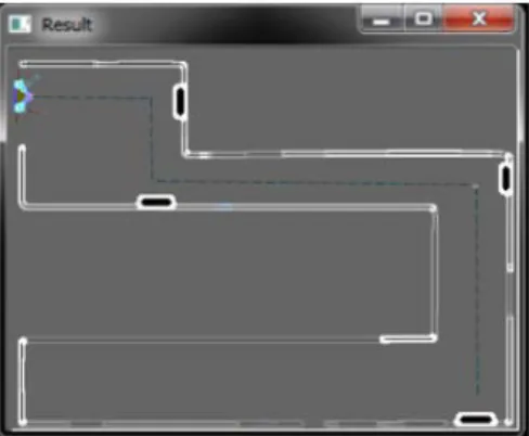
The robot makes localization and mapping depending on the artificial landmarks that are placed in the environment. The system reduces the localization errors by using Kalman filter. So, the robot can make localization and mapping with less errors in the environment. The experimental results of the mobile robot localization and mapping in the environment using a camera, three ultrasonic sensors and encoders are shown in Figure.21. In this mapping system, blue line represents the real trajectory and blue dot line shows the estimated location and map of the mobile robot in the environment. The artificial landmarks are shown with black color rectangle shapes
Figure 21: The mobile robot starts localization and mapping in the environment
The experimental results of the mobile robot localization and mapping in the environment using a camera, three ultrasonic sensors and encoders are shown in Figure.22. . The robot detects the landmark which is in front of it.
321
If there is landmark which is in the front wall of the robot, the robot will make detection and measure the distance of these landmarks by using camera and front ultrasonic sensor and also the other two ultrasonic sensors makes wall and obstacles detection not to be collide while localization and continuously makes mapping by using wheel encoders. This results show that the robot can make localization and mapping with less position estimation errors by using Kalman filter and artificial landmarks.
Figure 22: Mapping along the moving way of mobile robot localization with sensor fusion in indoor environment
When making localization and mapping, the robot can find out and face with obstacles in the environment. The robot can detect and avoid the obstacles effectively by using three ultrasonic sensors that are mounted on each side of the vehicle. Mobile robot localization and mapping with obstacle avoidance is shown in Figure.23 and the obstacle is shown with square shapes. The robot made localization and mapping successfully in the structured indoor environment with less uncertainty position errors. In this system, artificial landmarks are used to reduce uncertainty and Kalman filter is also used for lessen the errors in the position estimation of mobile robot.
Figure 23: Mobile robot localization and mapping with obstacle avoidance using sensor fusion in indoor environment
In this research, localization and mapping system are also tested by using with camera only. If the system uses only vision sensor, the robot can estimate the position with much errors than using sensor fusion system. The experimental results of localization and mapping system using a camera is shown in Figure.24.
322
Figure 24: Mobile robot localization and mapping using camera only in indoor environment
If a robot needs to gain a more or less complete information of its environment, it cannot rely only on one type of sensor. Since a single sensor is not capable of doing the task, sensor fusion rises in importance. Information from different sensors are obtained and combined to find the location of the robot, detect obstacle and avoid it. So, sensor fusion is applicable for mobile robot navigation.
6.Conclusions
In this research, self-localization and mapping system for autonomous mobile robot navigation is used in a structured indoor environment. It is based on the visual detecting process by fusing with the ultrasonic sensor sensing and encoder method. Artificial landmarks were used for robot localization, in which landmark distances and landmark recognition were worked out using camera and ultrasonic sensor. By using the artificial landmarks, the robot can reduce the uncertainty in the environment while estimating the position more accurately. In addition, the coordinates of each detected landmark were combined with distance to the robot from wheel encoders for estimation of the robot location. The system is based on Kalman Filter, which utilizes the data between previous observed position and the detection of artificial landmark to correct the position and orientation of the mobile robot. This method is applicable to mobile robot localization and proved to achieve solutions with less computational times. The system only needs to focus on the area which has artificial landmark to extract feature while making localization. So, this system is able to reduce the cost and computational time up to 15 minutes because of the sensor fusion and image processing techniques. In this research, map-based self-localization and mapping system is used to be more efficient in the structured indoor environment.
7.Recommendation
Results in both simulation and real world experiments show that the maps obtained present high quality and are able to effectively localize in the environment. The results show that it is possible to use of robots to explore and navigate in known environments. However, some limitations identified in this system are that there will be walls in the environment so that the ultrasonic sensors can sense effectively and can control the mobile robot to go straight. This system can’t be used in outdoor environment. If we want to use this mobile robot in outdoor environment, the system have to use natural landmarks that are in the environment.
323
Acknowledgements
The author is deeply gratitude to Dr. Sint Soe, Rector of Mandalay Technological University (MTU) for his kind permission to submit this research. The author would like to thank all the teachers from the Department of Mechatronic Engineering, Mandalay Technological University (MTU). And she also would like to thank her family and her friends who have helped her throughout the year.
References
[1] I. J. Cox and G. Wilfong (Editors), Autonomous Robot Vehicles, Springer-Verlag, New York (1990).
[2] D. L. Hall and J. Llinas, “A challenge for the data fusion community I: Research imperatives for improved processing,” in Proc. 7th Natl. Symp. on Sensor Fusion, Albuquerque, NM, Mar. 1994.
[3] J. Leonard and H. Durrant-Whyte, “Mobile robot localization by tracking geometric beacons,” Robotics and Automation, IEEE Transactions on, vol. 7, no. 3, pp. 376 –382, jun. 1991.
[4] W. Burgard, D. Fox, D. Hennig, and T. Schmidt, “Estimating the absolute position of a mobile robot using position probability grids,” in Proc. of the National Conference-on Artificial Intelligence, 1996.
[5] G. Grisetti, D. L. Rizzini, C. Stachniss, E. Olson, and W. Burgard. Online constraint network optimization for efficient maximum likelihood map learning. In Proc. of the IEEE Int. Conf. on Robotics & Automation (ICRA), 2008.
[6] R. K¨ummerle, G. Grisetti, H. Strasdat, K. Konolige, and W. Burgard. g2o: A general framework for graph optimization. In Proc. of the IEEE Int. Conf. on Robotics and Automation (ICRA), 2011.
[7] A. Howard, M. Mataric, and G. Sukhatme, “Relaxation on a mesh: a formalism for generalized localization,” in Proc. of the IEEE/RSJ Int. Conf. on Intelligent Robots and Systems (IROS), 2001.
[8] C. Rafflin and A. Fournier, “Learning with a friendly interactive robot for service tasks in hospital environments,” Autonomous Robots, vol. 3, pp. 399–414, 1996.
[9] H. Hu and D. Gu. Landmark-based navigation of autonomous robots in industry. International Journal of Industrial Robot, 27(6):458–467, November 2000.
[10] E. Jones, A. Vedaldi, and S. Soatto, “Inertial structure from motion with autocalibration,” in Proceedings of the Internetional Conference on Computer Vision - Workshop on Dynamical Vision, 2007.
[11] J. Kelly and G. S. Sukhatme, “Visual-inertial sensor fusion: Localization, mapping and sensor-to-sensor self-calibration,” Int. Journal of Robotics Research, vol. 30, no. 1, pp. 56–79, 2011.
324
[12] M. C. Silpa-Anan, S. Abdallah, and D. Wettergreen, Development of autonomous underwater vehicle towards visual servo control. Proceedings of the Australian Conference on Robotics and Automation. Melbourne, Australia (2000)
[13] I. J. Cox and G. Wilfong (Editors), Autonomous Robot Vehicles, Springer-Verlag, New York (1990).
[14] J. L. Crowley, Mathematical foundations of navigation and perception for an autonomous mobile robot. Reasoning with Uncertainty in Robotics (1995)
[15] I. Loevsky and I. Shimshoni, “Reliable and efficient landmark-based localization for mobile robots,” Robotics and Autonomous Systems, vol. In Press, 2010.
[16] J. Leonard and H. Durrant-Whyte, “Mo-bile robot localization by tracking geometric beacons,” Robotics and Automation, IEEE Transactions on, vol. 7, no. 3, pp. 376 –382, jun. 1991.
[17] W. Burgard, D. Fox, D. Hennig, and T. Schmidt, “Estimating the absolute position of a mobile robot using position probability grids,” in Proc. of the National Conference-on Artificial Intelligence, 1996.
[18] G. Grisetti, D. L. Rizzini, C. Stachniss, E. Olson, and W. Burgard. Online constraint network optimization for efficient maximum likelihood map learning. In Proc. of the IEEE Int. Conf. on Robotics & Automation (ICRA), 2008.
[19] R. K¨ummerle, G. Grisetti, H. Strasdat, K. Konolige, and W. Burgard. g2o: A general framework for graph optimization. In Proc. of the IEEE Int. Conf. on Robotics and Automation (ICRA), 2011.
[20] A. Howard, M. Mataric, and G. Sukhatme, “Relaxation on a mesh: a formalism for generalized localization,” in Proc. of the IEEE/RSJ Int. Conf. on Intelligent Robots and Systems (IROS), 2001.
[21] J. Gonzalez, A. Stentz, and A. Ollero, “An iconic position estimator for a 2d laser range finger,” Proc. of IEEE International Conference on Robotics and Automation, pp. 2646-2651, 1992.
[22] F. Cheanvier and J. Crowley, “Position estimation for a mobile robot using vision and odometry,” Proc. of IEEE International Conference on Robotics and Automation, pp. 2588-2593, 1992.
[23] K. Sugihara, “Some location problems for robot navigation using a single camera,” Computer Vision, Graphics and Image Processing, vol. 42, no. 1, pp. 112-129, 1988.
[24] M. Grewal and A. Andrews, Kalman filtering: theory and practice, Prentice-Hall, Inc., Englewood Cliffs, New Jersey (1993).
[25] G. Hager and S. Atiya, “Real-time vision-based robot localization,” IEEE Trans. on Robotics and Automation, vol. 9, no. 6, pp. 785-800, 1993.