grids. In: The 15th International Conference on AC and DC Power
Transmission. IET, Stevenage. (In Press) ,
This version is available at
https://strathprints.strath.ac.uk/65998/
Strathprints is designed to allow users to access the research output of the University of Strathclyde. Unless otherwise explicitly stated on the manuscript, Copyright © and Moral Rights for the papers on this site are retained by the individual authors and/or other copyright owners. Please check the manuscript for details of any other licences that may have been applied. You may not engage in further distribution of the material for any profitmaking activities or any commercial gain. You may freely distribute both the url (https://strathprints.strath.ac.uk/) and the content of this paper for research or private study, educational, or not-for-profit purposes without prior permission or charge.
Any correspondence concerning this service should be sent to the Strathprints administrator:
The Strathprints institutional repository (https://strathprints.strath.ac.uk) is a digital archive of University of Strathclyde research outputs. It has been developed to disseminate open access research outputs, expose data about those outputs, and enable the
Interoperability of Different Voltage Source Converter
Topologies in HVDC Grids
Deyang Guo
1*, M.H. Rahman
1, G.P. Adam
1, Lie Xu
1, Abdullah Emhemed
1, Graeme Burt
1and Yash
Audichya
21 University of Strathclyde, Glasgow, UK, 2 The National HVDC Centre, Glasgow, UK
Keywords: Interoperability; Voltage source converter;HVDC transmission systems; modular and hybrid multilevel converters; multi-terminal DC grids; offline and real-time simulations.
Abstract
This paper presents a detailed study of DC grid operation using a range of user-defined offline and real-time HVDC converter models which were rigorously validated against offline and real-time benchmarks. Provided that these models are destined for use in real-time hardware in the loop simulation and a wide range of offline system studies, this paper assesses their suitability for studying complex DC grids that consist of multiple voltage source converters which differ in their control range and fault ride-through capabilities. Detailed quantitative studies show that the offline and real-time DC grid models produce well matched results and provide efficient approaches to investigate DC grid operation during normal condition and AC and DC faults.
1
Introduction
In the last decade, a number of multilevel voltage source converters have been proposed for HVDC applications. Half-bridge (HB) and full-Half-bridge (FB) modular multilevel converters (MMC) have emerged as the preferred topologies for commercial application to multi-terminal HVDC grids. In the meantime, several hybrid converters have been proposed as alternatives that offer important trade-offs between footprint, semiconductor loss, resiliency to AC and DC network faults and control range. Some of these hybrid converters are becoming increasingly attractive as they offer bespoke features, ranging from that of the HB-MMC to the FB-MMC. Although the construction of large-scale DC grids using different converter topologies is important from both practical and market point of view, particularly for prevention of monopoly in supply chains, ensuring safe and reliable operation of DC grids with such diversity, present significant technical challenges; especially, during fault conditions. Meaningful assessments of the interoperability of such complex DC grids, with equipment supplied by multiple vendors, require converter models with steady-state and transient behaviours that accurately resemble the typical behaviour of physical systems. All converter terminals (regardless of their topologies) must be designed to ensure that
their steady-state and transient responses are confined within narrow band and with defined settling and rise times, maximum overshoots, permissible oscillating frequency, and damping in order to avoid undesirable interactions between converters.
With regard to modelling, concerted efforts from academia and industry in the last decade have resulted in development of universal modelling frameworks for MMC and hybrid converters, namely, Thevenin equivalent model which was initially developed in 1969 by Dommel in [1] and then extended to MMC in [2, 3], generalized switching function model [4-6], and averaged model [7, 8]. Detailed studies presented in [3, 6, 9-13] confirm that all the aforementioned models are capable of reproducing the typical behaviours of modular and hybrid converters during normal operation, and AC and DC faults.
Equally, the control of MMC and hybrid converters is extensively investigated in the last decade [14-22]. There are two common methods for controlling MMC and hybrid converters. The first method only manipulates the phase and magnitude of the AC voltage component for each phase-leg relative to that of AC grid as that in the two-level converter, with the DC components of the phase-legs fixed. The second method manipulates both AC and DC components of each phase leg to control active and reactive powers, and to decouple capacitor voltage regulation and dynamics from that of the DC link voltage.
The second control method allows the HB-MMC to control its DC link independent of the cell capacitor voltages and vary its DC link voltage and retain control as long as the DC voltage remains above the peak of the line-to-line voltage being imposed by the AC grid at its AC terminals. It permits FB-MMC to offer maximum control range in addition to DC fault blocking, i.e., controlled operation over wide range of positive and negative DC link voltages. Similarly, besides the DC fault blocking, hybrid MMC with 50% FB cells and 50% HB offers controlled operation between zero to rated positive DC link voltage.
Because of numerous mismatches between the attributes and capabilities of the voltage source converters briefly highlighted earlier, this paper examines the suitability of the offline and real-time converters’ models being developed in this study for detailed assessment of interoperability of different converters in a meshed DC grid. Interoperability of a few selected
representative converter topologies, namely, the HB and FB MMCs and hybrid MMC consisting of 50% FB cells and 50% HB will be assessed quantitatively using offline PSCAD and real-time RSCAD simulations. This study models all converter terminals using validated averaged models against their switching function equivalents in PSCAD and RSCAD with all main and auxiliary controllers incorporated [11].
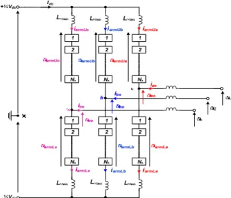
Fig. 1: Basic circuit of three-phase modular multilevel converter
2
Converters modelling and control
2.1Modelling
Fig. 1 shows a generic power circuit of a three-phase MMC converter. It consists of six arms, with each arm comprising of an inductor and a chain link of HB or FB cells, or combination of the HB and FB cells. Fig. 2(a) shows generic phase legs of the HB and FB MMCs and of the hybrid MMC. The upper and lower arm voltages (VarmU and VarmL) of the converters in Fig. 1 can be approximated as:
1
2 sin( )
armU carmU carmU U
V V -m t+ V m (1)
1
2 sin( )
armL carmL carmL L
V V +m t+ V m (2) where VcarmU and VcarmL are the sums of the upper and lower arm capacitor voltages, and must be regulated such that
*
carmU carmL carm dc
V V V V ( *
carm
V is the rated arm capacitor
voltage).is the DC modulation index defined as *
dc carm
V V
, mU and mL are the upper and lower arms modulation functions, respectively. For HB and FB MMCs, DC modulation indexes ‘α’ vary narrowly around 1 and 1- 1, respectively. Fig. 2 (b) and (c) depict per arm averaged models of the half-bridge and full-bridge MMCs [7, 11, 23, 24], where the equivalent upper and lower capacitor currents icapU and icapL are:
1
2 sin( )
capU armU armU U
i i -m t+ i m (3)
1
2 sin( )
capL armL armL L
i i +m t+ i m (4) Realization of blocking state in HB-MMC model in Fig. 2 (b) is achieved by adding the auxiliary devices Sx and Dm [11]. In
FB-MMC model in Fig. 2 (c), blocking state is realized by gating off the insulated gate bipolar transistors (IGBTs) S1, S2,
S3 and S4, and setting the upper and lower arm modulation
functions mU=mL=1. The upper and lower arm voltages during de-block state are realized as:
armU carmU U
V V m (5)
armL carmL L
V V m (6)
In addition, when sign(mU)≥0 the switches S1 and S4 are turned
on and S2 and S3 are turned off, and the opposite is true for
sign(mU)<0. The former scenario arises when FB-MMC arm
synthesizes positive voltages, and latter scenario when the FB-MMC arm synthesizes negative voltages. The hybrid FB-MMC facilitates normal and reduced DC link voltage operation and active control of DC fault current during pole-to-pole DC fault (zero DC voltage) by inserting the same number of cell capacitors with positive and negative polarities as that of the FB-MMC. Thus, provided that the HB and FB cells of the hybrid MMC have same capacitances, insertion of the FB cell capacitors with positive polarities will exhibit the same behaviours at cell and arm levels as that of the HB cells. This fact justifies the use of per arm averaged model depicted in Fig. 2(c) to represent the hybrid MMC (or mixed-cell MMC), provided the DC modulation control range is restricted as described above, and upper and lower arm modulation functions mU and mL are set to ½ during converter blocking.
Sx Sm S1 S2 S3 S4 HB HB HB HB HB HB Larm Larm a -½Vdc +½Vdc FB FB FB FB FB FB Larm Larm a -½Vdc +½Vdc HB HB FB HB HB FB Larm Larm a -½Vdc +½Vdc FB FB (a) (b) (c)
Fig. 2: Generic depictions of: (a) Phase-legs of half and full-bridge Modular and hybrid converters, (b) Enhanced per arm averaged model of the half-bridge MMC, (c) Enhanced per arm averaged model of full-bridge and hybrid MMC.
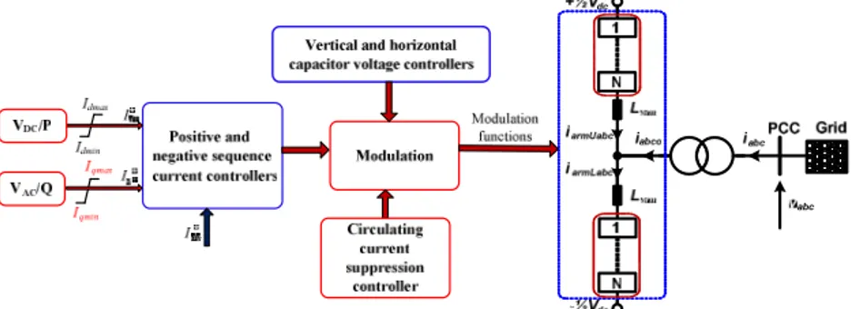
Fig. 3: High-level block diagram of the main and auxiliary MMC controllers
2.2Control system
Fig. 3 summarises the main and auxiliary controllers employed in this paper with HB, FB MMCs and hybrid MMC. The outer controllers on d-axis regulate active power or DC voltage and set the positive sequence d-axis current order. Likewise, the outer controllers on q-axis regulate reactive power or AC voltage and set the positive sequence q-axis current order. The inner current controllers regulate both positive and negative sequence currents and limit current contribution to AC fault and generate the AC components of the modulation functions. The negative sequence d- and q-axis current orders are set to zero to ensure balanced three-phase output currents during operation in unbalanced AC grids and asymmetric AC faults, but their orders can be set to other values if negative sequence current is required. Circulating current controller is implemented in each phase leg to suppress the 2nd order
harmonic currents in the arms of the converters to reduce semiconductor power losses and cell capacitor voltage ripples. Horizontal and vertical cell capacitor voltage controllers are implemented to ensure equal voltage distribution across the three phase-legs of the converters and across the upper and lower arms of each phase leg. With averaged converter models adopted in this paper, each arm in Fig. 3 will be replaced by the averaged arms in Fig. 2 (b) or (c), depending on the converter topology to be simulated.
3
Test system
Fig. 4 shows an example test system being used to assess the interoperability of HB and FB MMCs and hybrid MMC in a generic DC grid. Converters T1, T2 and T3 are hybrid MMC,
FB-MMC, and HB-MMC respectively. All converters are represented in PSCAD-EMTDC and RTDS-RSCAD by their averaged models described in Section 2.1 and shown in Fig. 2 (b) and (c). The control system depicted in Fig. 3 is incorporated into each converter station. Simulation parameters of the test systems are shown in Fig. 4.
The DC grid shown in Fig. 4 is implemented in RTDS using the concept of multi-rate, with two distinct sampling times. The power circuits of the three converters and DC cables are placed in 3 processors on GPC cards that operate at 2.5μs time step. The three AC grids, control systems and part of the averaged model that calculates the capacitor voltage dynamics, operate at 50μs time step. Three AC sources that represent the AC grids and dynamics of the averaged model are placed in 2 processors
on GPC card. The AC sides of the three converter models that operate at 2.5μs (small) time-steps are interfaced to the AC grids that operates at 50μs (large) time-step via three interfacing transformers. The DC side of the converter model and associated DC cable operate at small time-step but in different processors and are linked together through very short T-lines to form a DC grid.
It is worth emphasizing that the uses of T-lines for connecting converter models and DC cables that operate on different processors and the interfacing transformers for connecting system components that operate with different sample times have negligible impact on the accuracy of the real-time simulation, which will be demonstrated later.
Fig. 4: Illustrative DC grid with multiple converter topologies
4
Simulations
This section examines the use of the developed offline and real-time converter models described in Sections 2 and 2.2 to assess the performance of DC grid that consists of multiple converter topologies, considering normal operation and fault conditions.
4.1Normal operation
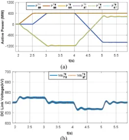
Fig. 5 displays RSCAD simulation waveforms superimposed on their PSCAD equivalents, where PS and RT subscripts stand for PSCAD and RTDS simulations respectively. In the simulations of the DC grid in Fig. 4, converter T3 controls the
DC grid voltage at 640kV, whilst T1 and T2 are operated as
follows: at t=2s, T2 ramps its active power from 0 to 600MW
at a rate of 1200MW/s; at t=2.5s, T1 ramps its active power
output from 0 to 600MW at the same rate whereas within t=4-5s it reverses power from 600MW to -1000MW. Throughout this paper, converters T1, T2 and T3 maintain their reactive
The active power and DC voltage in Fig. 5 (a) and (b) show that the DC voltage controlling converter T3 (HB-MMC)
regulates its DC link voltage tightly around 640kV and adjust
its active power exchange with the AC grid G3 as the power
controlling converters T1 (hybrid MMC) and T2 (FB-MMC)
vary their active power set-points. These expected behaviours
(a)
(b)
Fig. 5: Simulation waveforms that validate the steady-state performance and different dynamics of the offline DC grid model against that of the real-time equivalents as converters T1 and T2 vary their active power set-points (real-time superimposed on the offline): (a) active powers of the T1, T2 and T3, (b) DC voltage of the converter terminal T3 .
are replicated accurately by both the offline PSCAD and real-time RTDS simulation waveforms, see Fig. 5 (a) and (b).
4.2Three-phase–to-ground AC fault
Fig. 6 shows real-time RTDS simulation waveforms superimposed on their PSCAD equivalents when the system is subjected to a 300ms temporary three-phase AC fault at converter T2 AC terminal at t=6s. In the pre-fault condition,
converters T1 and T2 control their active power outputs at
500MW and 600MW respectively, and converter T3 maintains
the DC grid voltage at 640kV.
Fig. 6 (a) shows the active powers of converters T1, T2 and T3
measured at the grid sides of the transformers B1, B2 and B3
respectively. The DC voltage shown in Fig. 6 (b) is briefly disturbed at the occurrence of the three-phase AC fault at T2,
which creates a temporary imbalance between AC and DC powers. The brief drop observed in the DC voltage is an indication of the deficit in the DC power as a result of a loss of the active power from the converter T2, see Fig. 6 (a) - (c).
During the fault, T2 operates at current limit as seen in the arm
and output phase currents displayed in Fig. 6 (d) and (e). Notice that the DC components of the arm current of T2 drop to zero
when its active power transfer capability collapses with the AC voltage at B2 down to zero as shown in Fig. 6 (f). Since
simulation waveforms displayed in Fig. 6 (a) through (f) show good agreement between the offline PSCAD and real-time RTDS models, and in line with broader theoretical understanding of DC grid behaviours during AC faults; it is concluded that both models are well-suited for AC fault studies of complex DC grids that employ different converter topologies.
(a) (b)
(c) (d)
(e) (f)
Fig. 6: Simulation waveforms of the offline DC grid model when converter T2 is subjected to a solid three-phase symmetrical AC fault at B2: (a) Active powers of the converter terminals T1, T2 and T3, (b) DC voltage of the converter terminal T3, (c) DC current of the T2 terminal, (d) Samples of the upper and lower arm currents of T2, (e) Converter T2 three-phase output currents measured at B2, (f) Converter T2 three-phase voltages measured at B2.
4.3Pole-to-pole DC short circuit fault
This section presents DC fault simulation waveforms when a permanent pole-to-pole DC short circuit is applied at the main DC fault node (F2) at t=4s and both converters T1 and T2
control their active powers at 600MW prior to the fault. All converters are blocked after 50µs after fault inception. Fig. 7 (a) and (b) show the pole-to-pole DC voltage at F2 and DC link
currents of the three converters, with the DC link currents of the T1 (hybrid MMC) and T2 (FB-MMC) drop to zero after the
activation of the converters blocking, while converter T3
(HB-MMC) continues to feed current into the DC fault through its AC supply. The plots in Fig. 7 (c) show the active powers of converters T1 and T2 drop to zero immediately after blocking,
while T3 continues to draw reduced active power from AC grid
G3 to feed the entire system losses during the DC fault. Similar
behaviour can be observed from the DC current as Fig. 7 (d), (e) and (f) show the arm currents of T1 and T2 drop to zero and
that of the T3 reverses direction and is fed from the AC side.
The DC voltages and currents, active powers and arm currents shown in Fig. 7 (a) through (f) are well matched between the offline and real-time simulation waveforms in terms of different dynamics and magnitudes during transients associated with the DC faults. Therefore, it is concluded that the presented models are well-suited for detailed DC fault studies in highly complex DC grids that consist of multiple voltage source converter topologies.
(a) (b)
(c) (d)
(e) (f)
Fig. 7: Simulation waveforms of the offline DC grid model when a pole-to-pole DC short circuit fault is applied at the main DC node that links the three the converters: (a) Pole-to-pole DC fault measured at the fault point, (b) DC link current measured at DC terminals of converters T1, T2 and T3, (c) Active powers of the converter terminals T1, T2 and T3, and (d), (e) and (f) samples of the upper and lower arm currents of the converter terminals T1, T2 and T3.
5
Conclusion
The rapid growth in the use of real-time hardware-in-the-loop simulation studies in order to facilitate extensive validations of the control and protection of HVDC systems in recent years have called for the development of rigorous models which are accurate and can be considered with high certainty as true representation of the physical systems. In response to this call, this paper has presented a summary of detailed quantitative study that assesses the interoperability of different converter topologies that operate side-by-side in a multi-terminal DC grid, with particular emphasis on the suitability of the models. Detailed examinations of the presented results, with the simulation waveforms of the real-time models superimposed on that of the offline PSCAD, reveal that both models being compared produce practically identical results during normal
and abnormal conditions. On these bases, it has been concluded that the offline and real-time simulation models employed in this paper are well-suited for a wide range of DC grid studies such as normal operation, and AC and DC faults.
Acknowledgements
The project is sponsored by The National HVDC Centre.
References
[1] H. W. Dommel, "Digital Computer Solution of Electromagnetic Transients in Single-and Multiphase
Networks," Power Apparatus and Systems, IEEE
Transactions on, vol. PAS-88, no. 4, pp. 388-399, 1969. [2] U. N. Gnanarathna, A. M. Gole, and R. P. Jayasinghe,
Converters (MMC) on Electromagnetic Transient
Simulation Programs," Power Delivery, IEEE
Transactions on, vol. 26, no. 1, pp. 316-324, 2011. [3] G. P. Adam and B. W. Williams, "Half- and Full-Bridge
Modular Multilevel Converter Models for Simulations of Full-Scale HVDC Links and Multiterminal DC Grids,"
IEEE Journal of Emerging and Selected Topics in Power Electronics, vol. 2, no. 4, pp. 1089-1108, 2014.
[4] C. Oates and C. Davidson, "A comparison of two methods of estimating losses in the Modular Multi-Level Converter," in Power Electronics and Applications (EPE 2011), Proceedings of the 2011-14th European Conference on, 2011, pp. 1-10.
[5] G. P. Adam, P. Li, I. A. Gowaid, and B. W. Williams, "Generalized switching function model of modular multilevel converter," in 2015 IEEE International Conference on Industrial Technology (ICIT), 2015, pp. 2702-2707.
[6] R. Li, L. Xu, and D. Guo, "Accelerated switching function model of hybrid MMCs for HVDC system simulation," IET Power Electronics, vol. 10, no. 15, pp. 2199-2207, 2017.
[7] J. Xu, A. M. Gole, and C. Zhao, "The Use of Averaged-Value Model of Modular Multilevel Converter in DC Grid," IEEE Transactions on Power Delivery, vol. PP, no. 99, pp. 1-1, 2014.
[8] F. B. Ajaei and R. Iravani, "Enhanced Equivalent Model of the Modular Multilevel Converter," Power Delivery, IEEE Transactions on, vol. PP, no. 99, pp. 1-1, 2014. [9] J. Peralta, H. Saad, S. Dennetiere, J. Mahseredjian, and S.
Nguefeu, "Detailed and averaged models for a 401-level
MMC-HVDC system," in 2013 IEEE Power & Energy
Society General Meeting, 2013, pp. 1-1.
[10] J. Xu, A. M. Gole, and C. Zhao, "The Use of Averaged-Value Model of Modular Multilevel Converter in DC Grid," IEEE Transactions on Power Delivery, vol. 30, no. 2, pp. 519-528, 2015.
[11] D. Guo et al., "Detailed quantitative comparison of half-bridge modular multilevel converter modelling methods," presented at the The 14th IET International Conference on AC and DC Power Transmission (ACDC 2018), China, 28-30 June 2018, 2018.
[12] H. Saad, K. Jacobs, W. Lin, and D. Jovcic, "Modelling of MMC including half-bridge and Full-bridge submodules for EMT study," in 2016 Power Systems Computation Conference (PSCC), 2016, pp. 1-7.
[13] S. Denneti et al., "Validation of a MMC model in a real-time simulation platform for industrial HIL tests," in 2015 IEEE Power & Energy Society General Meeting, 2015, pp. 1-5.
[14] R. Li, L. Xu, L. Yao, and B. W. Williams, "Active Control of DC Fault Currents in DC Solid-State Transformers During Ride-Through Operation of
Multi-Terminal HVDC Systems," IEEE Transactions on
Energy Conversion, vol. 31, no. 4, pp. 1336-1346, 2016. [15] Z. Rong, L. Xu, L. Yao, and B. W. Williams, "Design and
Operation of a Hybrid Modular Multilevel Converter,"
Power Electronics, IEEE Transactions on, vol. 30, no. 3, pp. 1137-1146, 2015.
[16] W. Xiang, W. Lin, L. Xu, and J. Wen, "Enhanced Independent Pole Control of Hybrid MMC-HVDC System," IEEE Transactions on Power Delivery, vol. PP, no. 99, pp. 1-1, 2017.
[17] G. P. Adam and I. E. Davidson, "Robust and Generic Control of Full-Bridge Modular Multilevel Converter
High-Voltage DC Transmission Systems," IEEE
Transactions on Power Delivery, vol. 30, no. 6, pp. 2468-2476, 2015.
[18] R. Li, G. P. Adam, D. Holliday, J. E. Fletcher, and B. W. Williams, "Hybrid Cascaded Modular Multilevel Converter With DC Fault Ride-Through Capability for
the HVDC Transmission System," IEEE Transactions on
Power Delivery, vol. 30, no. 4, pp. 1853-1862, 2015. [19] E. C. Mathew, M. B. Ghat, and A. Shukla, "A
Generalized Cross-Connected Submodule Structure for Hybrid Multilevel Converters," IEEE Transactions on Industry Applications, vol. 52, no. 4, pp. 3159-3170, 2016.
[20] Z. Suo, G. Li, L. Xu, R. Li, W. Wang, and Y. Chi, "Hybrid modular multilevel converter based multi-terminal DC/DC converter with minimised full-bridge submodules ratio considering DC fault isolation," IET Renewable Power Generation, vol. 10, no. 10, pp. 1587-1596, 2016.
[21] G. Bergna et al., "A Generalized Power Control Approach in ABC Frame for Modular Multilevel Converter HVDC Links Based on Mathematical Optimization," IEEE Transactions on Power Delivery,
vol. 29, no. 1, pp. 386-394, 2014.
[22] Q. Tu, Z. Xu, and L. Xu, "Reduced Switching-Frequency Modulation and Circulating Current Suppression for Modular Multilevel Converters," Power Delivery, IEEE Transactions on, vol. 26, no. 3, pp. 2009-2017, 2011. [23] N. Ahmed, L. Angquist, S. Norrga, A. Antonopoulos, L.
Harnefors, and H. Nee, "A Computationally Efficient Continuous Model for the Modular Multilevel Converter," Emerging and Selected Topics in Power Electronics, IEEE Journal of, vol. PP, no. 99, pp. 1-1, 2014.
[24] H. Barnklau, A. Gensior, and S. Bernet, "Derivation of an equivalent submodule per arm for modular multilevel converters," in Power Electronics and Motion Control Conference (EPE/PEMC), 2012 15th International, 2012, pp. LS2a.2-1-LS2a.2-5.