DOI: 10.12928/TELKOMNIKA.v15i1.4051 238
Received October 3, 2016; Revised December 26, 2016; Accepted January 18, 2017
Model and Analysis of Multi Level Multi Frequency RF
Rectifier Energy System for Low Power Supply
Application Device
Budi Herdiana*1, Bobi Kurniawan2
Electrical Engineering Department, Indonesian Computer University (UNIKOM), Jl. Dipatiukur No. 102-116 Bandung 40132, phone / fax: 022-2504119 / 022-2533754
Corresponding author, e-mail: [email protected]*1, [email protected]
Abstract
Sustainable energy for the mobile electronic devices always needed during the energy storage batteries capacity in the mobile electronic devices are limited for a few hours for the usage time. To get a long lasting operating time from the mobile electronics equipment sets, the energy source should always be connected into the device. In this paper, we were proposed a charging energy method via wireless operation supply using the microwaves (RF) radiated by the air multi-frequency. The RF to DC rectifier circuit is a major component for changing the RF wave to an electronic current (DC). The Dickson models were used as an approach to superiority includes a simple series, low DC ripple factor, etc. The design, analysis, and the experimentation from the rectifier circuit have been conducted and presented in this paper. In the measurement, the mobile electronic devices placed at a distance about 5 meters from the energy source with the system voltage DC 3.7V, and have been obtained at the working frequency between 825 - 960MHz with the PCE values 12-33%, and a ripple factor of ± 0,01%. The charging time energy is needed about 4 hours at the research trial room, and about 11 hours outdoor had been observed. Based on these results, the wirelessly energy charging method for the mobile electronic devices is a potential methods to resolve the sustainable energy issue and the green technology supporting with the most programs.
Keywords: the wireless energy charging, RF to DC rectifier circuit, the Dickson models, sustainable energy
Copyright © 2017 Universitas Ahmad Dahlan. All rights reserved.
1. Introduction
The increasing number of mobile phone devices use today led to the availability of power supply energy for the telecommunications equipment becomes necessary in order to keep communication going. The power supply energy sources had only rely on the energy sources with the grid AC 220V also has some limitations, especially when we are in a away position from the energy grid source because the habit of mobile phone users always have the high mobility while the consistency of the energy needs the power supply always must remain unfulfilled. Therefore, to reduce these limitations, it would require another energy source that can be used as an alternative energy such as electromagnetic waves, solar cell, and others. The alternative energy sources are easily obtained is certainly one of them is the availability of RF energy which is quite abundant around us for example the RF energy coming from the base stations, access points (Wi-Fi) or the ISM band. Basically power supply voltage derived from RF energy sources will be of little value because the characteristics of the RF power itself is very small when detected with increasing transmission losses to the projection distance. Therefore, if you want a power supply corresponding voltage device to be fed, it would be require the rectifier models that have the ability to convert RF energy into DC at the same time have the ability amplifies the voltage to the voltage levels in order to support the existing power supply power supply devices [1,5]. This paper described with the draft structure rectifier circuit multilevel RF energy to be applied into the multi-frequency low power supply as a mobile phone charger system with using a modified approach the Dickson's model where the schottky diode HSMS2822 as the main component.
2.The RF Rectifier Circuit Concept
The Wireless power transfer technology can be used as a source of alternative power supply for mobile devices when the power supplies of existing resources have limitations in providing the sustainable energy. One application from this technology is RF to DC converter which is a system of electromagnetic wave rectifier RF energy into DC energy. The rectifier system was built by two main components of the antenna as catcher RF energy in space and as a modifier RF wave rectifier into DC, the stages of rectifier as shown in Figure 1.
Base Stations Satelite Communication Wireless Internet (WiFi) Radio Communication TV Brodcast Sumber-sumber Energi RF Antena Matching Circuit Rectifier Charging Controller Baterai Wireless Communication
Figure 1. The Wave Rectifier Systems RF to DC [2, 6]
The characterization of a rectifier system multi-frequency RF energy as in Figure 1 above can be analyzed based on the average power received simultaneously where the amount defined by [2]: (1)
As for the frequency with the input power i to DC power-i obtained by:
(2)
While the DC power from the input of various multi-frequency RF power sources is a result of the strengthening of antennas and RF power all i received are valued at [1]:
(3)
In the Equation 2 and 3 above every power that is detected will be amended to the input power, strengthening and distance expressed by Friis formula for [3]:
(4)
Basic circuit built as F as a regulator and the driving signal rectification of magnitude expressed by the equation:
(5)
I h y Δ ( ) h equation 5 to the amount of:
TELKOMNIKA Vol. 15, No. 1, March 2017 : 238 – 244
The Model RF energy rectifiers always keep a brief of the needs and accomplishments of which one was a rectifier Dickson Models are described as follows:
Figure 2. Multi Level Rectifier Circuit Model [1]
3.Research Methods 3.1. System Design
Overview block model designed system is expressed as Figure 3.
In p u t E n e rg i R F
Antena Multiband Matching Impedance
(Wideband) RF to DC (Multistage Rectifier) DC to DC Converter (Portable)
Figure 3. Block System Design
Designed rectifier model is a modified model of the Dickson rectifier where the construction side of the circuit is basically applied by some voltage multiplier circuit with arranged in the stages according to the results shown in the following modification development [4, 7]:
(7)
The circuit model of the whole system is described as Figure 4.
RF Input HSMS2822 10nF 10nF 10nF 10nF 10nF 10nF HSMS2822 HSMS2822 HSMS2822 HSMS2822 10nF 10nF 10nF 10nF 10nF CL 10uF RL 100 K MAX756 L 150 uF 100 nF Rcapture R1= 1K 100 nF IN5817 ke Batere Vref ref Gnd FB R2 R3 OUT 10nF
Model and Analysis of Multi Level Multi Frequency RF Rectifier Energy… (Budi Herdiana) Based on Figure 4, the process to raise the output voltage of the rectifier to the voltage level of mobile phone power supply devices that will be supplied then used the tracking method h h h h ΔR (C ) DC DC converter circuit, which is determined by the equation:
(8)
While the output voltage of system ( ) was obtained using the equation:
(9)
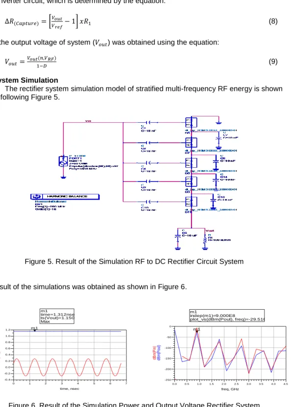
3.2. System Simulation
The rectifier system simulation model of stratified multi-frequency RF energy is shown as the following Figure 5.
Figure 5. Result of the Simulation RF to DC Rectifier Circuit System
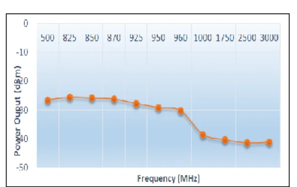
The result of the simulations was obtained as shown in Figure 6.
Figure 6. Result of the Simulation Power and Output Voltage Rectifier System
4.Testing and Measurement
System testing is done to obtain system performance through the stages of theoretical approaches, simulation and measurement devices related to the power to be achieved. Illustration from the test results data can be described as:
1 2 3 4 5 6 0 7 -0.2 0.0 0.2 0.4 0.6 0.8 1.0 -0.4 1.2 time, nsec ts( V in ), V ts( V ou t), V Readout m1 m1 time= ts(Vout)=1.150 Max 1.312nsec 0.5 1.0 1.5 2.0 2.5 3.0 3.5 4.0 0.0 4.5 -200 -150 -100 -50 -250 0 freq, GHz dB m (P ou t) m1 dB m (P in ) m1 indep(m1)=
TELKOMNIKA Vol. 15, No. 1, March 2017 : 238 – 244 (a)
(b)
Figure 7. Performance Characteristic Curve of Rectifier Multistage Circuit System
4.1. Step-up Voltage Regulator
Step-up Voltage Regulator is used to step-up the output voltage rectified according to working voltage of mobile telephone equipment (3,7 Volt). To ensure the qualified performance of components, the tests facilitated indoor (in the test room) and outdoor, and the result is shown as Table 1-2.
Table 1. Test Result (indoor) Energy resource RF Distance (d) = 5 m
Vout [Volt] Mobile Battery Condition Pr [dBm] Frequency [MHz] + 40 500 0,74 No charging 825 4,47 Charging 850 4,45 Charging 870 4,27 Charging 925 4,10 Charging 950 3,85 Charging 960 3,81 Charging 1000 0,50 No charging 1750 0,20 No charging 2500 0,08 No charging 3000 0,03 No charging
Table 2. Test Result (outdoor) Distance [meter] Output Voltage [Volt] Frequency detected [MHz] Mobile Battery Condition 1 4,5 950,5 Charging 2 4,3 950,5 Charging 3 4,1 950,5 Charging 4 3,9 950,5 Charging 5 3,8 950,5 Charging 5,5 2,9 950,5 No charging
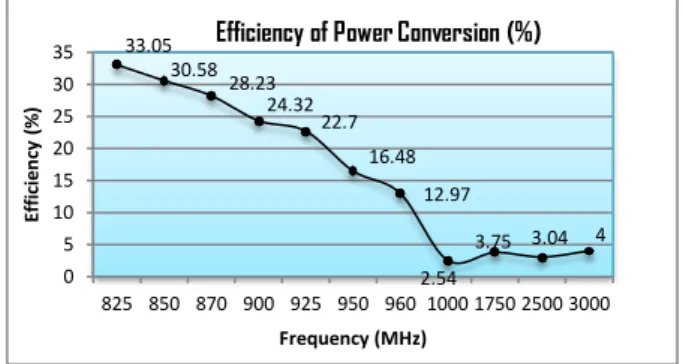
4.2. The Power Conversion Efficiency
The efficiency of power conversion can effect into the voltage and power resulted by system according to energy supply to mobile battery. The result is shown as Figure 8.
Figure 8. Curve of System Efficiency Characteristic
4.3. The Duration of Battery Energy Charging
The direct test in site is very important to ensure and to give qualified work system totally designed. The sequence of the measurement is shown as Figure 9.
Figure 9. Hardware System Test
The result of charging data duration is shown in Table 3.
Table 3. Test Result (indoor) Frequency [MHz] Vout [Volt] Pout [mW] Charging Duration 825 4,47 894 4 hours 10 minutes 850 4,45 890 4 hours 26 minutes 870 4,27 854 4 hours 39 minutes 925 4,10 820 4 hours 47 minutes 950 3,85 770 5 hours 14 minutes 960 3,81 762 5 hours 35 minutes
Table 4. Test Result (outdoor) Frequency [MHz] Vout [Volt] Pout [mW] Charging Duration 825 4,50 411 9 hours 16 minutes 850 4,30 387 9 hours 52 minutes 870 4,10 372 10 hours 12 minutes 925 3,90 353 10 hours 46 minutes 950 3,80 342 11 hours 04 minutes 960 3,50 0 No charging > 960 < 3,00 0 No charging 33.05 30.58 28.23 24.32 22.7 16.48 12.97 2.54 3.75 3.04 4 0 5 10 15 20 25 30 35 825 850 870 900 925 950 960 1000 1750 2500 3000 Ef fi ci enc y (% ) Frequency (MHz)
TELKOMNIKA Vol. 15, No. 1, March 2017 : 238 – 244 5. Conclusion
The modification of the multi- q y y R RF D ’ model resulted that the rectifier model is easy to be implemented. The modification of system is contributing to technology of mobile battery wireless recharging system. The efficiency of power conversion is about 12-33% with ripple 0,01% in frequency range 825-960 MHz, with distance 5m from energy source and recharging duration about 4 hours indoor and 11 hours outdoor. This result shows the potential energy solution in the future especially in using the renewable energy and any resources in RF as a new energy.
References
[1] Bounanno A, Pavone. Design Considerations for Radio Frequency Energy Harvesting Devices.
Journal of International Progress In Electromagnetics Research. 2012; 45(1): 19-35.
[2] Ufuk Muncuk. Design Optimization and Implementation for RF Energy Harvesting Circuits. MSc Thesis. Boston: Northeastern University. 2012.
[3] TS Rappaport. Wireless Communications Principles and Practice. Second Edition. New Jersey: Prentice Hall PTR. 2002: 107-113.
[4] A Taudeshki. Development of a New Cascade Voltage-Doubler for Voltage Multiplication. Chinese
Journal of Engineering Hindawi Publishing Corporation and Center for Advance Power and Energy Research (CAPER) Universiti Putra Malaysia. 2014; 1(1): 1-6.
[5] DS Liu, Feng Bo Li, XC Zou, Yao Liu, XM Hui, XF Tao. New Analysis and Design of a RF Rectifier for
RFID and Implantable Devices. International Journal of Open Access Sensor. 2011; 11(11):
6495-6508.
[6] NM Din, CK Chakarbarty, A Bin Ismail, KKA Devi, WY Chen. Design of RF Energy Harvesting
System for Energizing Low Power Devices. International Progress in Electromagnetics Research.
2012; 132(1): 49-69.
[7] Ajay S, KJ Jegadishkumar. A Highly Efficient Power Management System for Charging Mobile
Phones Using RF Energy Harvesting.International Journal of Information Technology Convergence
![Figure 1. The Wave Rectifier Systems RF to DC [2, 6]](https://thumb-us.123doks.com/thumbv2/123dok_us/9651728.2845554/2.892.146.748.300.504/figure-wave-rectifier-systems-rf-dc.webp)
![Figure 2. Multi Level Rectifier Circuit Model [1]](https://thumb-us.123doks.com/thumbv2/123dok_us/9651728.2845554/3.892.164.714.167.1191/figure-multi-level-rectifier-circuit-model.webp)