Institute of Architecture of Application Systems University of Stuttgart
Universitätsstraße 38 D–70569 Stuttgart
Bachelor Thesis No. 308
Provisioning of Docker Containers
with TOSCA
Kevin Gödecke
Degree: Bachelor of Science, Softwaretechnik
Examiner: Prof. Dr. Dr. h. c. Frank Leymann Supervisor: Dipl.-Inf. Santiago Gómez Sáez
Commenced: December 14, 2015 Completed: June 14, 2016
Abstract
In order to master the administration and automation problem of distributed applications in the cloud age, topology & orchestration platforms have been established in the past few years. Application topologies and their entire lifecycle can easily be modeled and later on be deployed on various cloud environments. Standards like the Topology and Orchestration Specification for Cloud Applications (TOSCA) help to keep the description of applications platform independent and increase interoperability between components. Another recent paradigm in Cloud Computing is containerized virtualization. The particular and significant popularity of Docker containers was mainly driven be the needs of having less dependencies when moving from development to production environments. The technology around Docker container still evolves very fast and projects to provision and manage Docker container in a automated way have already been adopted by major Cloud providers (e.g. Amazon ECS1, Azure Container Service2, Google Container Engine3), but lack in topology & orchestration platforms like Cloudify4 or OpenTOSCA5. The cloud provider offerings use container cluster technologies like Apache Mesos or kubernetes under the hood, as the lifecycle management of container is a complicated task. Container cluster technologies provide an easy way to automatically scale, deploy and manage multiple Docker container on various infrastructures.
This thesis aims to enable the support for the deployment of clustered Docker containers using a TOSCA compliant topology & orchestration language and execution environment. More specifically, the Cloudify environment is used as the basis to enable the modeling and deployment of container clusters hosted on kubernetes. By the usage of the Cloudify platform the interoperability with other non-containerized applications and general platform independence is assured, while still taking advantage the container cluster features. The resulting system is able to orchestrate, manage and scale application components individually, regardless of the underlying cloud technology.
1https://aws.amazon.com/ecs/
2https://azure.microsoft.com/en-us/services/container-service/ 3https://cloud.google.com/container-engine/
Zusammenfassung
In den letzten Jahren haben sich neue Herausforderungen durch den steigenden Verwaltungs- und Administrationsaufwand für verteilte Anwendungen in Cloud-Umgebungen ergeben. Um dieser Problematik entgegenzuwirken haben sich Topology & Orchestration Plattformen etabliert, welche es ermöglichen Topologien für Anwendun-gen und deren gesamte Lebenszyklen einfach zu modellieren und später auf verschieden Cloud Umgebunden zu deployen. Standards wie die Topology and Orchestration Specifi-cation for Cloud AppliSpecifi-cations (TOSCA) ermöglichen es Anwendungen plattformunab-hängig zu beschreiben, um ein höheres Maß an Interoperabilität zwischen einzelnen Komponenten zu gewährleisten. Ein weiteres sehr verbreitetes Paradigma im Bereich Cloud Computing stellt die Container-Virtualisierung dar. Die steigende Beliebtheit von Containern, und speziell Docker Containern, ist zurückzuführen auf die Loslösung von sämtlichen Abhängigkeiten durch die Container-Virtualisierung, welche zum Beispiel zu einem barrierefreie Prozess beim Umzug von Entwicklungs- auf Produktionssys-teme führt. Insbesondere Technologien rund um Docker Container entwickeln sich aktuell äußert schnell weiter und auch Provider wie Google, Amazon und Microsoft haben bereits Technologien zur automatisierten Provisionierung von Docker Containern eingebunden (z.B. Amazon ECS6, Azure Container Service7, Google Container Engine8). Da es sich bei der Verwaltung des gesamten Lebenszyklus, sowie der Skalierung von Container um eine komplexe Aufgabe handelt, bauen diese Services auf sogenannte Container Cluster Technologien auf. Container Cluster Technologien ermöglichen es containerisierte Anwendungen zu skalieren, deployen, ohne jegliche Abhängigkeiten zur unterliegenden Infrastruktur.
Diese Arbeit stellt Ansätze vor, um in einer TOSCA-basierten Topologie- & Orchestrierung-sumgebung, Docker Container in Clustern zu deployen und auszuführen. Im Detail wird eine Cloudify-Umgebung als Basis für die Bereitstellung von geclusterten Containern durch Kubernetes verwendet. Die Cloudify Plattform ermöglich hierbei die Verbindun-gen zwischen nicht-containerisierten und containerisierten Anwendungskomponenten, während durch das Container Cluster nach wie vor Skalierung, Load Balancing und Service Discovery zur Verfügung gestellt wird. Das Gesamtsystem ist somit in der Lage Anwendungskomponenten individuell und unabhängig zu skalieren und zu verwalten. Als weitere Teil der Arbeit wird ein Ausblick gegeben, in welche Richtung ein solches System entwickelt werden kann, falls bereits angekündigte Technologien realisiert wer-den.
6https://aws.amazon.com/ecs/
Contents
1 Introduction 13
1.1 Motivation & Problem Statement . . . 14
1.2 Outline . . . 14 2 Fundamentals 17 2.1 Cloud Computing . . . 17 2.1.1 Deployment Models . . . 17 2.1.2 Service Models . . . 18 2.1.3 Providers . . . 20
2.2 Topology & Orchestration . . . 21
2.2.1 Application Topology . . . 22
2.2.2 Orchestration . . . 22
2.2.3 TOSCA . . . 23
2.3 Container Based Virtualization . . . 29
2.3.1 LXC . . . 30
2.3.2 Docker . . . 30
2.4 Container Compatible Cloud Services . . . 32
2.4.1 Amazon Beanstalk . . . 33
2.4.2 Amazon ECS . . . 33
2.4.3 Google Container Engine . . . 34
2.4.4 Microsoft Container Service . . . 36
2.4.5 Comparison . . . 36 3 Related Work 37 4 Specification 41 4.1 Requirements . . . 41 4.1.1 Functional Requirements . . . 41 4.1.2 Non-Functional Requirements . . . 42
4.2 Use Case Description . . . 43
5 System Design 55
5.1 Architecture . . . 55
5.1.1 Containers . . . 55
5.1.2 Cloud Application Specification . . . 55
5.1.3 Topology & Orchestration Platform . . . 56
5.1.4 Container Cluster Technology . . . 58
6 Implementation 63
7 Validation 79
8 Conclusion & Future Work 91
List of Figures
2.1 Cloud Deployment Models . . . 17
2.2 Cloud Service Models . . . 19
2.3 Example of a simple application topology . . . 22
2.4 Structure of TOSCA service templates [OAS13] . . . 24
2.5 OpenTOSCA ecosystem components [Uni16] . . . 25
2.6 OpenTOSCA architecture [BBH+13] . . . 26
2.7 Lego4TOSCA Node Types [HLNW14] . . . 27
2.8 Cloudify Architectural Overview [Gig16a] . . . 28
2.9 Comparison of Hypervisor-based Virtualization (right) and Container-based Virtualization (left) [Ber14] . . . 29
2.10 A typical Docker deployment workflow . . . 31
2.11 Cloud Provider Container Services Overview . . . 33
2.12 Google Container Engine Components - Kubernetes Overview . . . 35
3.1 Ubernetes Architecture [Kub16c] . . . 38
4.1 Distributed Containerized Application Deployment Use Cases . . . 44
4.2 Architectural System Overview . . . 51
5.1 Container Cluster Environment . . . 60
5.2 Cloudify Kubernetes Cluster Provisioning . . . 61
7.1 Validation Workflow . . . 79
7.2 Cloudify Dashboard on AWS . . . 81
7.3 Application Overview . . . 81
7.4 Cloudify Dashboard - Blueprint Topology Overview . . . 85
7.5 Cloudify Dashboard - Create Deployment Dialog . . . 86
7.6 Cloudify Dashboard - Blueprint Deployment Overview . . . 86
7.7 Cloudify Dashboard - kubectl scale Workflow . . . 88
List of Tables
4.1 Description of Use Case: Model Distributed Application . . . 45
4.2 Description of Use Case: Deploy Containerized Application . . . 47
4.3 Description of Use Case: Scale Application . . . 48
4.4 Description of Use Case: Monitor Application . . . 49
4.5 Description of Use Case: Tear Down Application . . . 50
List of Listings
2.1 TOSCA Simple YAML Example [OAS16b] . . . 25
2.2 Distributed web application modeled in YAML for Docker Compose . . . 32
5.1 Cloudify Webserver Example [Gig16b] . . . 57
6.1 etcd Docker command . . . 63
6.2 flannel Docker command . . . 64
6.3 kubernetes Docker command . . . 64
6.4 flannel Docker command for minion host system . . . 65
6.5 kubectl command to start a service [Kub16a] . . . 65
6.6 kubectl command to expose a service [Kub16a] . . . 65
6.7 kubectl command to get service details [Kub16a] . . . 66
6.8 kubectl command to delete a pod or service [Kub16a] . . . 66
6.9 Docker installation using python and subprocess module . . . 72
6.10 Disable iptables and ip-masq for Docker Daemon . . . 72
6.11 Run ETCD in Docker Container . . . 73
6.12 Docker installation using python and subprocess module . . . 73
6.13 Run flannel using Docker image and save container ID . . . 73
6.14 Extract the flannel subnet configuration from running flannel Docker container . . . 74
6.15 Removal of the default docker0 bridge . . . 74
6.16 Start the kubernetes master as Docker container . . . 75
6.17 Install flannel on worker node . . . 76
6.18 Install flannel on worker node . . . 76
6.19 Run kubelet on worker node with master node IP . . . 77
6.20 Run kubelet proxy service . . . 77
7.1 Bootstrap Cloudify Manager VM on AWS . . . 80
7.2 MongoDB Blueprint Modeling . . . 82
7.3 Kubernetes Cluster Modeling . . . 83
7.4 Application Service Modeling . . . 84
1 Introduction
One of the reasons Cloud Computing has emerged so quickly in the last couple of years is the immense benefit of being able to run applications in a distributed manner. Major Cloud providers like Amazon1, Microsoft2and Google3 have extended their offerings in the Platform-as-a-Service sector (PaaS) to provide customers with services to make it even easier and faster to deploy distributed containerized applications without taking care of the underlying infrastructure. The provisioning support for container-based virtualization approaches like Docker has been adapted by most Cloud providers (e.g. Amazon ECS4) to further simplify the deployment process and enable users to automate processes like scaling and load balancing. Additionally recently evolved container cluster technologies like Apache Mesos or kubernetes, which are partly used by major cloud providers in their PaaS offerings, also provide interesting approaches on the way to keeping affords of deployment and maintenance to a minimum level.
In order to manage and describe such highly sophisticated applications and services it requires standards and frameworks to build a common ground between cloud providers. Standards like the Topology and Orchestration Specification for Cloud Applications (TOSCA)[OAS16a] have been evolved to describe and manage topologies and orchestra-tion of applicaorchestra-tions in a cloud platform portable way and thus enhance the portability of cloud applications through describing their lifecycle, requirements and relationships. The recent trend of container-based virtualization techniques has helped developers to further close the gap between development and production environments. Nevertheless the ability to enable TOSCA specified applications to be provisioned with container-based virtualization techniques like Docker5 would help significantly to improve the interoperability of distributed applications in the cloud and will be the subject of this thesis.
1https://aws.amazon.com/
2https://azure.microsoft.com/en-us/services/cloud-services/ 3https://cloud.google.com/
1 Introduction
1.1 Motivation & Problem Statement
In todays IT and business world, applications become more and more complex. Different application components run on different platforms, require individual hardware and might even have special security or privacy constraints. Cloud computing in general provides a solution to parts of the stated problem, such as providing the underlying resources, but raises new problems like the organization and management of the ap-plication components itself. The containing components might have dependencies between one another or have to fulfill other platform specific requirements before being able to start. In order to fully automate entire lifecycles a topology and orchestration specification as well an execution engine is required. The Topology and Orchestration Specification for Cloud Applications (TOSCA) provides such a standard and is already well established in the industry. While topology describes how the application and its components are modeled in a platform neutral way, the orchestration describes the automation of deployment and other management tasks. By specifying the topology and orchestration details it is possible to automate the entire lifecycle of cloud applications. The recent establishment of containerized virtualization approaches also opens new challenges for the orchestration of distributed cloud applications. While part of the topology & orchestration description is the creation of new node types, which also define the custom behavior during management operations, the design and implementation of such types for container and especially Docker container has only recently been tried to approach. Furthermore the technology around Docker containers is still evolving very quickly and new technologies like container cluster technologies appear very frequently. In order to fully take advantage of such new technologies in topology & orchestration platforms, it requires to extend and define the behavior and structure of these newly adopted technologies in a platform independent way, preferably using standards like TOSCA. The utilization of such practices to provision containerized, distributed applications with respect to a TOSCA based orchestration platform will help to automate processes for cloud applications and will be the subject of this thesis.
1.2 Outline
This thesis is structured in the following way:
Chapter 1 – Introduction: Brief introduction to the topic and disclosure of its motiva-tion and problem statement.
Chapter 2 – Fundamentals: This chapter covers the fundamentals that are required during the course of this thesis. The basics of modern Cloud Computing will
1.2 Outline
be discussed, as well as the Topology and Orchestration of applications in cloud environments. This further leads to Container-based virtualization techniques including Container Cluster Technologies.
Chapter 3 – Related Work: There are numerous approaches that have similar inten-tions or provide approaches on other platform or ecosystems. This chapter dis-cusses related work that interferes with the overall topic of this thesis.
Chapter 4 – Specification: This chapter specifies the requirements for the system, fol-lowed by the description of several use-cases as well as a high-level architectural system overview.
Chapter 5 – System Design: The overall system design details are covered and ex-plained in this chapter. This covers the technology-specific architecture as well the connection between them.
Chapter 6 – Implementation: This chapter outlines the implementation of the pro-posed system and its components.
Chapter 7 – Validation This chapter describes a use-case which validates the intro-duced system and its requirements. The execution of the use-case will be covered step-by-step.
Chapter 8 – Conclusion & Future Work Draws a conclusion of this thesis and provides an outlook on the future use of this work and related topics.
2 Fundamentals
2.1 Cloud Computing
Cloud Computing and Virtualization are the key principles that made it possible to provide an even easier network access to a large amount of resources. Resources like networks, servers, storage, applications or even services are maintained in a big pool and can be allocated and assigned dynamically [BGPV12]. Through the dynamic allocation the underlying hardware and infrastructure is utilized in the best possible way [VRCL08]. Through virtualization physical servers can be divided into multiple virtual machines by using a so called Hypervisor. Each virtual machine has resources assigned to it and runs a separate Operating System. The Cloud Computing paradigm has been widely adopted in both research and industry domains due to the efficiency of scaling and the possibilities to deploy and host applications in a distributed manner.
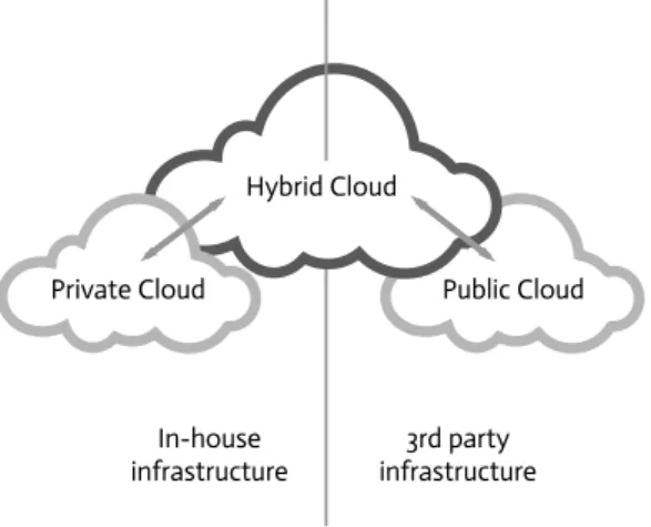
2.1.1 Deployment Models
A Deployment Model describes how the physical infrastructure of a Cloud is hosted and deployed. Public Cloud 3rd party infrastructure Hybrid Cloud Private Cloud In-house infrastructure
2 Fundamentals
1. Public Cloud Model
The Public Cloud Model provides an infrastructure which is accessible by the public and lets multiple users share the same infrastructure to reach maximum efficiency and reduce overhead [BGPV12]. The usage is mainly billed by a monthly pay-per-usage model. The infrastructure is maintained by the provider, who also offers management tools for users to control their environment and provision new resources within very few clicks. The resources and services vary between providers and reach from Virtual Machines to Object Storage solutions to Mobile Services like Push Notifications. Popular providers including Amazon AWS, Google Cloud Platform and Microsoft Azure cover most of the market share and offer a huge variety of services.
2. Private Cloud Model
The Private Cloud Model restricts public access and is mainly a result of security and privacy constraints within companies or organizations. The infrastructure is operated solely for single organization that can be divided into internal customers [BGPV12]. Interfaces similar to public cloud offerings are provided to employees and other eligible parties. A significant downside of a Private Cloud is the time and money intense maintenance which makes it only suitable for large scale enterprises and companies.
3. Hybrid Cloud Model
Multiple cloud infrastructures can be combined into what is often referred to as the Hybrid Cloud Model [BGPV12]. This approach is often chosen when it is important to keep only a certain amount of data within a private data center while non-sensitive data can be stored off-shore. An other use case is to extend the resources of a private cloud infrastructure in times of traffic peaks or unpredictable bursts. Computing capacity and resources can be increased through a connection to a public cloud provider. Bandwidth limitations play an important role when extending a Private Cloud and need to be considered closely.
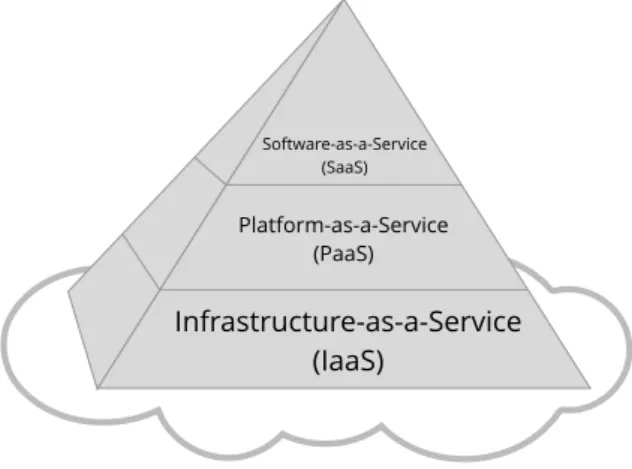
2.1.2 Service Models
Regardless of the selected deployment model the services offered within a cloud envi-ronment can be subdivided into different abstraction layers that have emerged over the last couple of years.
• Infrastructure-as-a-Service (IaaS) Model
2.1 Cloud Computing
databases or networks. The underlying physical hardware is fully virtualized to maximize elasticity and scaleability [DWC10]. This also means that new resources can be provisioned within a very short turnaround time in order to face temporary and unexpected workloads. One of the most popular services is Amazon Elastic Compute Cloud (EC2)1.
Infrastructure-as-a-Service (IaaS) Platform-as-a-Service (PaaS) Software-as-a-Service (SaaS)
Figure 2.2:Cloud Service Models
• Platform-as-a-Service (PaaS) Model
PaaS defines services which allow users to create, manage and run applications without maintaining the underlying infrastructure throughout their entire lifecycle. Clients are supplied with an application hosting environment that can be configured and be used automatically scale [BGPV12]. Examples include Amazon Beanstalk2 and Microsoft Azure Container Service3.
• Software-as-a-Service (SaaS) Model
SaaS provides the highest abstraction layer in the service model section. Software hosted on the Cloud infrastructure is offered to the user. Clients can access the software through an API or a interfaces like a WebGUI [FLMS11]. The provider takes care of hosting the entire application. The infrastructure as well as the platform is fully managed by the provider [BGPV12]. Popular examples include Google Docs4or SalesForce5.
1https://aws.amazon.com/ec2/
2https://aws.amazon.com/en/elasticbeanstalk/
3https://azure.microsoft.com/en-us/services/container-service/ 4https://docs.google.com/
2 Fundamentals
2.1.3 Providers
Cloud providers differ not only in deployment models but also in their services and service models. This thesis focuses on three major Cloud providers (Amazon AWS, Microsoft Azure, Google Cloud Platform) as they cover over 42% of the entire IaaS market share in 2014 [Sta16].
Amazon AWS
Amazon started its Cloud offerings in 2006 as a subsidiary of Amazon.com with just infrastructure services and has ever since constantly added services in the IaaS and PaaS sector. The first services offered were Amazon Elastic Compute Cloud (EC2), Simple Storage Service (S3) and Simple Queue Service (SQS)[Gar07]. Amazon EC2 provides scalable Virtual Machines based on the Xen virtualization, whereas S3 is an affordable object storage. Nowadays Amazon has spread its data centers across the globe with more than 12 geographical regions and 33 availability zones [Ama16].
A few services have claimed more and more popularity especially with regards the deployment of distributed applications. With Amazon Beanstalk a PaaS service is provided that lets users deploy scalable web applications and services with a few clicks. Beanstalk uses EC2 resources under the hood and as the service per se is free of charge, customers get billed for the usage of EC2 resources. Load-Balancing, scaling and monitoring is fully handled by Amazon, without any needs of maintaining the underlying infrastructure.
One of the very recently added services is Amazon ECS (EC2 Container Service) which lets you easily deploy containerized Docker applications. Users can manage and run these applications either from the web dashboard or through multiple SDKs or CLIs. The containerized Docker containers are being automatically deployed to Amazon EC2 instances which run a custom ECS agent that is being handled by the service. As of most of the Amazon services it integrates really well with any other offerings like for example Elastic Load Balancing.
Microsoft Azure
Microsoft Azure is a cloud platform by Microsoft started in 2010 to help developers build applications that are highly scalable and flexible. The cloud infrastructure is based on the Microsoft Azure Hypervisor (WAH) technology [QLDG09] and is often referred to as an classic example of a PaaS platform [Sav15]. IaaS is an other part of their offering
2.2 Topology & Orchestration
and doesn’t differ much from the competitors. The wide range of PaaS solutions that integrate especially really well with the .NET platform really set Azure apart.
Microsoft Azure Cloud Services lets you deploy your application in a fully automated way without taking care of the infrastructure, supporting Node.JS, PHP, Java, .NET Python and Ruby [Tul13].
Google Cloud Platform
The Google Cloud Platform provides multiple options in the PaaS and IaaS sector, giving the user different control over the environment. The Compute offerings can be divided into the following three services.
Google App Engine is a PaaS that provides support including Python, Java, PHP and Go to directly deploy and run applications, while letting Google take care of hosting, maintaining and scaling the infrastructure.
Google Container Engine was built due to the increasing impact of container-based development within the last couple of years. Developers can simply deploy their con-tainerized applications to a cluster that is running on Google Compute Engine instances with Kubernetes6.
Google Compute Engine is a IaaS that provides among others unmanaged Virtual Machines, while giving you control of the operating system and the environment.
2.2 Topology & Orchestration
Even though more and more cloud providers enter the market with all of them introduc-ing different offerintroduc-ings and services, the description of distributed application remains the same and thus forms a key principle in the process of providing interoperability between different cloud providers.
2 Fundamentals
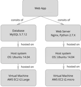
2.2.1 Application Topology
The term network topology is used to describe how resources in a computer network are organized and connected [Dav06]. The topology of distributed applications in Cloud environments describes how different parts of the application are structured and linked to one another. Distributed applications and in particular cloud services and their topologies need to be described in a proper way in order to take full advantage of cloud environments and later on provide interoperability between providers.
For example the Topology of a simple Flask web applications might consist of a MongoDB database and the web application itself. The application needs to run on a web server like Apache or Nginx, which additionally requires to run Pythn in order to execute the application per se. The connection towards the MongoDB database describes a necessary relationship to provide the application with data and the ability to persist data.
Web App
Database
MySQL 5.7.12 Nginx, Python 2.7.XWeb Server
Host system OS: Ubuntu 14.04
Virtual Machine AWS EC2 t2.micro Virtual Machine
AWS EC2 t2.Large Host system OS: Ubuntu 14.04 consits of hosted on hosted on hosted on hosted on consits of
Figure 2.3:Example of a simple application topology
2.2.2 Orchestration
Oxford dictionary defines orchestrating as "to plan or coordinate the elements of (a situation) to produce a desired effect, especially surreptitiously)" [Ste10]. In terms
2.2 Topology & Orchestration
of Cloud Computing orchestration describes the automation of creation, management and manipulation of cloud resources like compute, storage and network in order to realize a user requests [LMVF11]. These requests can differ significantly and are mostly modeled by complex workflows that handle the provisioning of underlying resources. Orchestration is not only limited to delivering a service utilizing a particular provider, it rather strives to utilize all possible providers to achieve the desired goal in the best possible way. As part of this the orchestration also includes the execution of workflows on different providers, which due to their internal service logic and vendor-specific gateways and APIs describes an other important challenge.
2.2.3 TOSCA
The Topology and Orchestration Specification for Cloud Applications (TOSCA) is an open standard for distributed cloud based applications. TOSCA was established in 2014 by the OASIS committee and is being used widely to describe application topologies in a platform independent way. This solves the common vendor-lock issue and additionally provides a way to connect components even across different cloud providers [OAS13]. Besides the definition and description of relations between components of cloud applica-tions, TOSCA also defines their life cycle. Life cycle definitions might later on be used by an orchestration engine to execute processes like deployment, scaling, termination or restart of the distributed application [BBLS12].
TOSCA is structured in a very simple and straightforward way. Service Templates describe topology as well as orchestration aspects through a specific TOSCA language. Figure 2.4 shows that each Service Template consists of a Topology Template, different Node and Relationship Types and Plans.
Topology Templates are further subdivided into Node and Relationship Templates. Node Templates have to be defined for different topology layers. A web application might have a Node Type (an instance of a Node Template) for a PHP application, which then is based on a Node Type that represents a Web Server, hosted on an other Node Type that models a cloud-hosted VM. Relationship Templates model connections between and to other Node Templates. Both Node Types as well as Relationship Types can have different properties and interfaces [BBH+13].
To describe entire workflows, TOSCA specifies so called Plans for management operations of components. Plans describe typically processes like termination and start and are based on existing workflow languages like BPEL and BPMN.
2 Fundamentals
Figure 2.4:Structure of TOSCA service templates [OAS13]
TOSCA Simple YAML Profiles
OASIS specified a Simple YAML Profile format to further simplify the way Service Templates and thus Cloud Applications are defined and specified. The ultimate goal is that over time through community contributions a repository of existing node and relationship types will grow to help other users speed up the specification process. This will also enable users to provide software specific scripts that start for example a service. The format expects to build on top of a few base types, which later one can be used in a hierarchical way [OAS16b].
Example of base types could include a Compute Node or a DBMS Node. Figure 2.1 shows an exemplary definition which builds on top of a base node type calledtosca.nodes.Compute
defined in thetosca_simple_yaml_1_0. my_serverthen has specific details defined like CPU,
2.2 Topology & Orchestration
tosca_definitions_version: tosca_simple_yaml_1_0
description: Template for deploying a single server with predefined properties. topology_template:
node_templates: my_server:
type: tosca.nodes.Compute capabilities:
# Host container properties host:
properties: num_cpus: 1 disk_size: 10 GB mem_size: 4096 MB
Listing 2.1:TOSCA Simple YAML Example [OAS16b]
OpenTOSCA Ecosystem
OpenTOSCA is a open source TOSCA-based ecosystem developed by the University of Stuttgart [Uni16]. Applications are provisioned in an imperative manner, meaning that applications are modeled through plans, which are similar to blueprints in Cloudify.
Modeling Tool
OpenTOSCA winery OpenTOSCA container OpenTOSCA vinothek Runtime Environment Self-Service Portal
Figure 2.5:OpenTOSCA ecosystem components [Uni16]
As shown in Figure 2.5 the OpenTOSCA ecosystem is separated in three key compo-nents. OpenTOSCA Container provides a runtime engine to execute management and deployment operations by using the CSAR (Cloud Service Archive) format. CSAR files include information to fully deploy and instantiate distributed cloud applications [Tre13]. Among other things a CSAR archive can include Service Templates, Node Types and Relationships. On top the winery adds a modeling tool for topologies and management plans and the so-called Vinothek enables users to provision new applications across cloud providers through a web interface.
2 Fundamentals
Figure 2.6:OpenTOSCA architecture [BBH+13]
Figure 2.6 gives a more detailed architectural overview of the OpenTOSCA container runtime component. In particular the runtime engine takes care of the execution of management operations, plan execution and application state management [BBH+13]. If needed the CSAR format can be extended with Implementation Artifacts in order to provide custom management operations. The Implementation Artifact Engine is generally responsible for the custom operations and for making them available in management plans. All plans are processed and validated by the Plan Engine and serve as a descriptor for management operations. A CSAR file can contain multiple plans which serve different needs like scaling, instantiating or similar. The controller component provides a general API access to add and remove CSAR files, whereas the remaining components and functions as an overlaying controller of the other components.
Lego4TOSCA
Lego4TOSCA builds on top of TOSCA and provides a generic format to describe reusable TOSCA node types. Figure 2.7 shows the basic nodes types of Lego4TOSCA called Building blocks. They can provided parameters on different hierarchical levels from infrastructural, which might include the configuration of an EC2 instance, to an operation
2.2 Topology & Orchestration
system level, which defines the operating system per se and certain runtime parameters [HLNW14].
Figure 2.7:Lego4TOSCA Node Types [HLNW14]
Cloudify
Cloudify is an open-source platform to orchestrate and manage distributed cloud appli-cations using the TOSCA specification. Similar to OpenTOSCA Cloudify provides tools to model applications and services, as well as a provisioning and orchestration engine. Through the usage of TOSCA the entire platform can provision multi-tier applications in a platform independent fashion. This gives users the possibility to even span application components across multiple providers [Gig16e].
Cloudify describes and provides tools to model topologies and orchestration configura-tions in blueprints which are defined using the YAML format and a specific Cloudify DSL (Domain Specific Language), which is derived from the TOSCA Simple YAML format specified by the OASIS committee. Blueprints include the application topology, work-flows and policies and describe the entire application lifecycle. Additionally blueprints include runtime related parameters like URLs, usernames or passwords.
2 Fundamentals
Figure 2.8:Cloudify Architectural Overview [Gig16a]
In figure 2.8 a general overview of the Cloudify Architecture is given.
Every Cloudify environment consists of a Cloudify Manager VM and multiple Application VMs. The Cloudify Manager VM provides access to a GUI as well as a Command Line Interface, which enables the user to manage application blueprints and provision and orchestrate them. The GUI further provides access to system and application monitoring and logging features as well as management tools to administrate deployed applications and blueprints.
Each provisioning task is described in Cloudify workflows, which are part of the modeling and can consist of custom Python and bash scripts. The Cloudify workflow engine, located on the Manager VM, parses the provided YAML application blueprint files and manages the orchestration tasks and their timing through the Task Broker. The Task Broker is built on top the Celery tasks broker, which is a asynchronous task queue based on distributed message passing system [Cel16] responsible for the distributed orchestration of tasks. The provisioning of common infrastructural resources like VMs or network interfaces is then passed onto a manager agent, which is also located within the Manager VM itself. After a successful deployment a general and a separate monitoring agent on the application VM report back to the central Manager VM in order for it to propagate the information to the user interface.
2.3 Container Based Virtualization
2.3 Container Based Virtualization
During the development process of an application developers usually work in their own development environment, which typically differs significantly from the environment that is later on used for production deployment. This directly leads to the problem of either adjusting the application to match the production environment or adjusting the deployment environment to match the application. Container based solutions promise a solution for this lack in the develop to deploy workflow, which is sometimes also referred to as "Dependency Hell" [Boe15]. On top this also provides a light weight alternative to full virtualization approaches [Mer14].
The main difference between virtualization and container-based virtualization is that it doesn’t fully emulate a hardware layer and thus uses a different architectural virtual-ization approach by sharing the underlying operating system [DRK14] (also see Figure 2.9). This means generally less isolation but significantly lower overhead in resources like storage and CPU.
Figure 2.9: Comparison of Hypervisor-based Virtualization (right) and Container-based Virtualization (left) [Ber14]
2 Fundamentals
2.3.1 LXC
LXC (i.e. LinuX Containers) are a container based virtualization method that uses core features of the Linux kernel like cgroups and kernel namespaces in order to isolate containers from one another. By accomplishing a detachment of users, processes and network management, LXC achieves a separation within a single host operating system. The Linux kernel namespace provides a separation of the user management for every container, so that root privileges and user rights don’t interfere and the host operating system can operate independently. A virtual network provides an abstraction layer for network interfaces of the container and an additional process namespace is responsible for isolating and managing processes on a container basis [XNR+13].
2.3.2 Docker
Docker containers are isolated packages of software that ship with their dependencies and config files already included. This makes it possible to run them in different environments out of the box.
The open source project uses different Linux-kernels and is build on the foundation of LXC features to achieve virtualization without setting up an entire operating system for every container [Boe15]. Each Docker container gets created by a Docker base image. New Containers can share base images (e.g. Ubuntu) and simply store new versions of files that get modified. This so called copy-on-write process is part of the AuFS (Advanced Multi-Layered Unification Filesystem) that Docker uses and is very efficient and light. When creating a new Docker image all steps taken are stored in the image and can then later on be used to re-create containers [Ber14].
Additional Dockerfiles can include instructions on what needs to be installed on top of a base image and can be used as a script to initially bring up the container and include environmental instructions like persistent storage, port mappings and further.
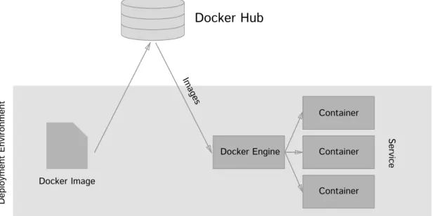
Docker Hub
Docker Hub is a central repository for Docker Images hosted by Docker, Inc. It enables users to collaborate on application and service container configuration, while providing features like automated builds, webhooks and more.
Typically Dockerfiles include a reference to Docker Hub in order to pull the required image and optionally resources. The image can be specified either directly through the repository/image name or via a Dockerfile. A Dockerfiles can additionally include further
2.3 Container Based Virtualization
instruction on the deployment process. After pulling the image successfully Docker can deploy the application. Figure 2.10 shows a workflow using Docker Hub as the Docker image registry. Se rvice De pl oy m en t E nv iro nm en t Docker Image Docker Hub Imag es Docker Engine Container Container Container
Figure 2.10: A typical Docker deployment workflow
Docker Swarm & Docker Compose
Orchestration of multiple Docker containers can be a challenging task. Containers in a distributed application may depend on one another and sometimes even require a specific starting order. The configuration and linking of multiple containers during the deployment process are key aspects that Docker Compose tries to solve. Through a single YAML file dependencies, links, volumes and other parameters can defined and later be used to boot up entire applications with just a single command. Docker Compose defines containerized parts of a distributed application as services [Tur14]. Listing 2.2 shows an example Python Flask web application consisting of a web service and a database service.
2 Fundamentals
web: build: .
command: python -u webapp.py ports: - "5000:80" volumes: - .:/mountVolume links: - database database: image: mongo:latest
Listing 2.2:Distributed web application modeled in YAML for Docker Compose
While Docker Compose provides an easy way to define relations in distributed con-tainerized applications through a single YAML file, Docker Swarm moreover adds native clustering support to the Docker ecosystem. This means multiple Docker hosts can virtually appear as a single host, while providing additional cluster scaling capabilities. Docker Swarm serves the standard Docker API, so other tools like Docker Compose can be pointed to a Swarm cluster just like to a single Docker host.
2.4 Container Compatible Cloud Services
Due to the increasing popularity among developers most cloud providers have adopted solutions to support the deployment of container-based applications. The most important provider specific solutions are described in the following.
2.4 Container Compatible Cloud Services
Container Services
Cluster In fr as tr uc tu re Co nt ai ne r Amazon EC2Container Service Azure Container Service Google Container Engine
Docker Swarm Amazon ECS
Cluster
Figure 2.11:Cloud Provider Container Services Overview
2.4.1 Amazon Beanstalk
Amazon Elastic Beanstalk (EBS) provides an easy way to deploy containerized applica-tions by providing a fully automated deployment, provisioning and monitoring platform on top of the AWS services. The underlying resources are provisioned by EBS and scale in and out to match user requirements and current workloads. All it requires is to upload and deploy an application to the environment.
2.4.2 Amazon ECS
Amazon ECS is a solution that lets you manage, scale and deploy containerized appli-cations to a cluster of Amazon EC2 instances. The cluster infrastructure is managed by Amazon and provides functionality for load balancing, auto scaling and other AWS services.
In order to deploy a containerized application to Amazon ECS the user has to assign EC2 instances or an Auto Scaling group to the cluster. All Nodes within a cluster run ECS container agents to connect to the Cluster and get thus get managed.
2 Fundamentals
Applications are defined by Task Definitions7 which can contain different, even linked Docker containers as well as their resources and limitations. A Task Definition that is executed in a cluster is called a Task. In order to maintain a required number of Task instances, Services have to be created. Services make sure failed Tasks are restarted or replaced by new ones to assure a desired count of running Tasks.
2.4.3 Google Container Engine
Google Container Engine provides a comparable solution to Amazons ECS service. Docker containers get deployed into a cluster of assigned VMs (provided under the hood through Google Compute Engine). The cluster size can be defined by the user and if necessary can be modified and scaled at a later point.
The cluster is operated and managed through Googles Kubernetes8, which is an open-source cluster management software which automates the deployment and management of containerized applications. Kubernetes supports different Container formats including the Docker container format.
Each Kubernetes cluster consists of a Kubernetes Master, which provides a publicly available API endpoint to communicate with the cluster. The Kubernetes Master is fully managed and thus doesn’t need to be maintained by the user. Besides the Kubernetes Master the cluster consists of nodes which run Docker Hosts and execute containers. Additionally each node runs a Kublet Agent in order to connect and get managed by the Kubernetes Master.
7http://docs.aws.amazon.com/AmazonECS/latest/developerguide/task_defintions.html/ 8http://kubernetes.io/
2.4 Container Compatible Cloud Services
Kubernetes Cluster
Nodes w. Kublet Agent
…
Container Pod
Dock
er Host
Nodes w. Kublet Agent
… Container Pod Container Pod Dock er Host … Kubernetes Master
…
…
Container PodFigure 2.12:Google Container Engine Components - Kubernetes Overview
To get an actual containerized application running in the cluster Pods need to be defined. A Pod is defined as "a group of one or more containers, the shared storage for those containers, and options about how to run the containers"9and is defined by parameters like the Docker image, the number of replications, environment variables and further details (see comparison table). Podsare very similar to "Task Definitions" in Amazons Container Service (ECS) and can be defined through the provided CLI tools or the Kubernetes Dashboard which runs on the Kubernetes Master. The Dashboard is preconfigured on the Kubernetes Master and is generally available through https:
//kubernetes-master-ip/ui.
In order to maintain a desired count of Podreplications, Kubernetes automatically sets
up a Replication Controller which internally deploys new Pods in case of crashes or
failures. Kubernetes Servicesprovide an abstraction layer for deployedPodsto guarantee consistent access (a proxy IP is assigned) to the application, while underlying containers might be switched out.
2 Fundamentals
2.4.4 Microsoft Container Service
By the time of this writing Microsoft Azure Container Service (ACS) is still in preview and is Microsofts attempt to provide a similar solution to Google Container Engine and Amazon ECS. The overall goal is to provide a platform to deploy containerized applications in a managed environment utilizing orchestration technologies like Apache Mesos10 with the Marathon Framework and Docker Swarm11.
During the initial cluster deployment the user can pick an Apache Mesos or Docker Swarm cluster deployment template to get started. The cluster management software will handle the underlying hardware and provide a way to easily scale and deploy containers. While Docker Swarm is directly able to handle Docker containers, Apache Mesos additionally requires Marathon12 to orchestrate containers. It comes preinstalled with the Apache Mesos template provided by Azure and provides on top a web interface very similar to the one of Kubernetes.
2.4.5 Comparison
In order to scale containerized applications Amazon ECS, Google Container Engine and Azure Container Service utilize different cluster technologies as described in the previous section. By using such the user is still in control of the underlying infrastructure and assigns nodes to the cluster. Amazon Beanstalk provides an additional layer of abstraction by fully managing the underlying infrastructure. The user simply has to upload an application and it gets automatically deployed on AWS. Provisioning, scaling, load balancing and health monitoring are entirely managed by the Beanstalk service.
10http://mesos.apache.org/
11https://docs.docker.com/swarm/overview 12https://mesosphere.github.io/marathon/
3 Related Work
This chapter provides a general overview about related technologies with respect to the provisioning of Docker containers on multi-cloud platforms using an orchestration engine. Special attention was drawn towards the integration and orchestration with existing non-containerized application components and the distribution across multiple cloud providers. Various technologies were analyzed that attempt to solve either the multi-cloud provisioning problem or the problem that solves mixing of non-containerized and containerized components.
Ubernetes is a project by Google and derives from the main kubernetes project1, which already provides a orchestration and provisioning platform for Docker containers. Uber-netes is still an early stage project, with various architectural and technological proposals but hasn’t reached a beta stage yet. A drawback kubernetes brings along is its incapabil-ity of deploying worker nodes or containers on multiple cloud providers simultaneously. Ubernetes aims to open up the kubernetes platform by providing higher availability, application portability to avoid vendor lock-ins, on- and off-premise hosting because of privacy sensitive data and capacity overflowing on public cloud offerings. All those use-cases have been generated by the latest feedback of developer and large companies and formed the needs of a solution like Ubernetes.
Figure 3.1 gives a high-level overview of current status of the proposed Ubernetes architecture. A overlaying Ubernetes API is suggested which controls the deployment of multiple independent kubernetes clusters into different Cloud environments. The Ubernetes API further handles kubernetes cluster as first class objects, meaning that each cluster registered, listed, described and deregistered via the API. Each kubernetes cluster is unaware of other clusters. The Policy Engine decides which applications are deployed into which cluster but coordinates closely with the Migration Controller and the Desired Federation State storage. The Migration Controller assures that the replications are running on the cluster as specified. The Desired Federation State storage is proposed to be similar to a distributed ETCD storage, which is already used in kubernetes as introduced in Chapter 2: Container Cluster Technologies. The Ubernetes project looks
3 Related Work
Ubernetes Control Plane Ubernetes API Policy Engine Auth Standard kubernetes API Migration Controllers Desired Federation State kubernetes Cluster e.g. on GCE kubernetes Cluster e.g. on AWS kubernetes Cluster e.g. Private Cloud
Figure 3.1:Ubernetes Architecture [Kub16c]
very promising, nevertheless by the time of this writing the project is not in a stage which is suitable for production use.
Part of the OpenStack system is the subproject OpenStack Heat2 which provides an orchestration and provisioning engine for the OpenStack cloud platform. Applications can be launched based on templates which are specified in simple text configuration files. A templates describes the overall structure of an application including server, floating IPs, volumes, security groups and further [Ope16]. Currently OpenStack Heat uses custom DSL. Currently a 2nd version of the OpenStack Heat DSL (Heat DSL23 is evolving which is planned to provide compliance to the TOSCA specification. As of right now OpenStack provides a toolkit (project Heat-Translator4to translate TOSCA specified application templates into Heat Orchestration Templates (HOT). In OpenStack provides a very interesting approach, which has a wide range of supported types and an interesting architecture. Custom plugins even allow it to run Docker containers as part of Heat templates. A major drawback of the OpenStack Heat system is that it is limited to the OpenStack eco-system, which never the less could combine on- and off-premise data centers.
The open-source project Kansible5 uses kubernetes and RedHats Ansible6 in order to combine the usage of container clustering with non-containerized applications or
compo-2https://wiki.openstack.org/wiki/Heat 3https://wiki.openstack.org/wiki/Heat/DSL2 4https://github.com/openstack/heat-translator 5https://github.com/fabric8io/kansible
nents. Kansable uses Ansible playbooks in order to configure and run non-containerized applications. A playbook is a file which specifies an applications configuration, deploy-ment and orchestration process. Playbook are also written in YAML and are very similar to the TOSCA Simple YAML Profile introduced in the Chapter 2. Kansible then allows to add the Ansible specified component to the kubernetes cluster and fully manage it. All kubernetes features are compatible including scaling, monitoring, service discovery and load balancing. A specifically assigned replication controller takes care of these tasks. Even though Kansible provides a way to host non-containerized applications within an existing kubernetes cluster, it is still tied down to the usage of one Cloud provider of the underlying kubernetes cluster. Further no compliance to a standard specification like TOSCA is provided, which further limits the portability of applications.
4 Specification
4.1 Requirements
This thesis aims to provide a orchestration & provisioning solution for distributed containerized cloud applications while providing a high level of platform interoperability. This section will outline the non-functional and functional requirements that the system must fulfill.
4.1.1 Functional Requirements
Application Modeling Tool: A tool is required in order to model distributed applications, including their topologies and orchestration tasks. Modeling plans can later on also be used to directly provision and deploy application using the provisioning & orchestration engine.
Virtualization Configuration: The modeling tool needs to provide support for different virtualization approaches, meaning that application components can be configured to run on bare Virtual Machine or within Docker Containers. The user will also have the possibility to connect components with different virtualization.
Configure Application Resources: Infrastructural resources (e.g. CPU, Memory, Net-work, ...) need to be configurable and allocated to specific application components. Deployment of Distributed Applications: The platform needs to provide interfaces to
provision and deploy distributed applications that have been modeled with the modeling tool. The deployment procedure should be accessible through a user interface.
Application Management Interface: An interface must be provided that gives easy ac-cess and control to the currently deployed applications. Application control opera-tions include deploying, starting, stopping, scaling and deleting.
4 Specification
Scale Applications: The user should also be able to scale running applications and their components up and down by increasing the replication count or the resources available.
Monitoring & Logging: A specific interface for logging and monitoring capabilities is required in order to provide the user with error reporting and continuous updates on the system status.
Runtime Environment: The user needs to be able to select on which platform the entire runtime environment as well as the applications is deployed on.
4.1.2 Non-Functional Requirements
Portability: To increase the portability of distributed applications compliance to the TOSCA specification must be given. This will enable the usage of multi-cloud applications, while avoiding a vendor-specific adaption. Additional support for Docker will also provide portability in terms of moving between production and development environments.
Interoperability: Different application components need to be able to operate with each other, no matter what virtualization approach is used or which underlying cloud provider is used.
Clustered Container Virtualization: The system needs to be able to fully support con-tainer virtualization and proper service discovery by the use of a Concon-tainer Cluster Technology.
Scalability: Deployed applications and separate components must be able to scale horizontally as well as vertically. Even containerized components need to be able to scale.
Failure Recoverability: In case of failure of an application component the system needs to be able to recover in an automated manner. Monitoring features need to continuously check if a component is properly running and trigger a restart or the deployment of a new replication.
Failure Isolation: The failure of a single application should have no direct impact on other applications.
Low Resource Overhead: The resource usage should have as little overhead as possible, while taking advantage of hyper-visor and container virtualization and container cluster technologies.
4.2 Use Case Description
Easy Handling: The system itself should despite its complexity be easy to handle and use.
Extensibility: It should be easy to extend the system in terms of new applications node types, cloud providers or other custom operations.
4.2 Use Case Description
In todays business world applications become bigger and more complex. Distributed applications evolve in complexity and contain different components. With an increas-ing complexity, components are distributed among infrastructure and might even be hosted using different environment technologies like for example Docker. On top of the increasing complexity of applications, the usage of different cloud providers for a single distributed application is becoming more and more common. Mixed on- and off-premise setups out of privacy constraints are just one of the reasons for the latest trends in this direction.
This thesis suggests different use cases in order to run a containerized distributed application while using an existing application running on bare infrastructure. This shows that existing components can be continued to use in system using containerized parts. The use case further requires for the containerized components to automatically scale in case of increased load, while still providing unified access to the service (proper Service Discovery). Besides the topological description, the application needs to be orchestrated in an automated fashion, which includes the continues monitoring of system status in order to guarantee a maximum level of reliability. Figure 4.1 gives an overview about all use cases.
4 Specification <<includes>> <<includes>> <<includes>> Tear down application Deploy containerized application Scale application Monitor
application ContainerMonitor
Provision Container Cluster Provision instances
Pull container image from repository Expose container
service
Model distributed application
<<includes>> <<includes>>
Figure 4.1: Distributed Containerized Application Deployment Use Cases
The following tables provide additional information about the use cases.
4.2 Use Case Description
Goal The user will be able to model complex distributed applications with a model-ing tool. The applications will especially consist of native and containerized application components, which need to be connected. Also support for different Cloud provider needs to be given.
Actor General User / Developer
Pre-Condition The modeling tool provides a given set of node types
Post-Condition The application is modeled in a way that can later on be used by a Topology & Orchestration engine to deploy the application.
Post-Condition in Special Case
The user needs to be provided with accurate error messages, if the modeling is incorrect.
Normal Case
1. The user builds a modeling plan out of existing components and node types
2. The modeling plan is valid
Special Cases
1a. The modeling tool provides not enough components
a) The user needs to be provided with options to the extend given modeling components
2a. The modeling plan is invalid
a) Provide accurate error messages that show inconstancies or other problems
2b. The modeling plan contains unknown types
a) The user needs to be provided with options to the extend given modeling components
4 Specification
Name Deploy Containerized Application
Goal The user wants to deploy a distributed application containing components running on bare infrastructure and some being containerized
Actor General User / Developer
Pre-Condition The user has already modeled the application components and its dependen-cies
Post-Condition The application with all its components was successfully orchestrated and deployed.
Post-Condition in Special Case
If the deployment fails then all resources should be teared down and the user needs to be informed about possible error sources
Normal Case
1. The user provides the modeling plan for the application
2. The Topology & Orchestration platform provisions the resources, in-cluding the container cluster
3. The container images get pulled from a central repository 4. The containerized components exposed their services 5. The components get orchestrated
6. The application is running and the orchestrated components are able to connect to each other
4.2 Use Case Description
Special Cases
1a. The model plan is incorrect or missing
a) The system points out sources of error in the modeling b) The system aborts the deployment
2a. The provisioning of resources fails
a) Rollback all actions and inform user about possible error sources 2b. The deployment of the container cluster fails
a) Rollback all actions and inform user about possible error sources 3a. The specified container image can’t be pulled
a) Inform user to provide a proper container image 4a. The service can’t be exposed
a) Check if an other service is exposing to the same port and report error sources
5a. Orchestration fails
a) Rollback all actions and inform user about possible error sources
4 Specification
Name Scale Application
Goal The user needs to be able to scale the deployed application vertically and horizontally.
Actor General User / Developer
Pre-Condition The application is already deployed and running with a containerized part on a container cluster
Post-Condition The application has scaled up or down according to the user input Post-Condition in
Special Case
If the scaling fails the application needs to recover its previous state
Normal Case
1. A distributed application with containerized components is already running
2. The containerized part that needs to be scaled will increase or decrease the replication count
3. New resources get provisioned and assigned to the cluster in order to scale the application up
4. The internal cluster load balancer distributes the traffic among the nodes
Special Cases
1a. No application is running
2a. A change of the replication count will not trigger the scaling
a) Check if changes have been applied, if not provide the user with an error message
3a. The resource provisioning or resource assignment to the cluster fails a) Provide an error message, but keep the service running
4a. The load is not balanced between the nodes
a) Monitoring capabilities need to watch if the load is balanced and in case of failure report with error messages
4.2 Use Case Description
Name Monitor Application
Goal The user needs to be able to monitor resources that have been provisioned.
Actor General User / Developer
Pre-Condition The application is already deployed and running with a containerized part on a container cluster, a workload can be monitored.
Post-Condition The user is informed about the current status of the resources and the application components
Post-Condition in Special Case
If no information is provided, provide access possibilities to control the resources manually
Normal Case
1. The user select the application that he wants to monitor, preferably in a dashboard
2. The user receives information like logging, status and load
Special Cases
1a. No application is running or selected
2a. No data is provided, it seems like the components are not being moni-tored
a) Check if there is no connection to the components and provided accurate error messages as well as possibilities to manually con-nect and monitor the components
4 Specification
Name Tear Down Application
Goal Applications and its components need to be able to be stopped and teared down
Actor General User / Developer
Pre-Condition The application is already deployed and running with a containerized part on a container cluster, a workload can be monitored.
Post-Condition The application is stopped and the resources are deallocated Post-Condition in
Special Case
Parts of the application are still running
Normal Case
1. The user select the application that he wants to terminate, preferably in a dashboard
2. The platform stops the service and tears down the resources, including the cluster if no other container components are running
Special Cases
1a. No application is running or selected 2a. The application is not able to be stopped
a) Provide possibilities to force an application to stop 2b. Parts of the application get stuck and won’t shut down
a) Provide possibilities manually tear down the resources
4.3 System Overview
4.3 System Overview
To accomplish the previously named features a system based on the following compo-nents is introduced. The compocompo-nents are also outlined in Figure 4.2. The system covers the entire workflow from modeling of an application over orchestration its components to scaling and managing the application throughout its lifecycle. This section gives an high level overview of the system whereas chapter 5 gives insights into the concrete implementation and the technology providers used.
Container Cluster Mas te r N od e
Modeling Tool Orchestration Engine Container Image Repository Cl us te r N od e Container Container Container Cl us te r N od e Container Container Container VM Instance
Modeling Engine Provisioning Engine
Database Instance
… Runtime Environment
Figure 4.2:Architectural System Overview 1. Modeling Tool
A modeling tool will be provided to model distributed applications as well as rela-tionships between them. The modeling will later be used by the orchestration & provisioning engine in order to deploy the distributed components. It’s noteworthy that the modeling of applications not only covers topological specifications, like in-frastructural requirements, but also states dependencies and other orchestrational details. The modeling mostly starts off with more generic types, which later on will derive into more specific node types like for example Cloud provider specific node types. An important part of a modeling tool is that it should be able to easily extend it in case new types are needed.
4 Specification
applying compliance to a standard like TOSCA a very high level of platform inter-operability for applications will be assured. The Topology & Orchestration Engine will take advantage of the TOSCA specification and provide functionality to execute deployments and other orchestrational tasks in various environments. Further the engine needs to be aligned with the modeling tool in order to application modeling structures and provision them.
3. Runtime Environment
In order to provide scaling capabilities monitoring functionalities of the runtime environment will assure accurate up and down-scaling of the underlying resources. A proper monitoring is also required to determine failure of running instances and maintain proper execution.
4. Container Cluster Technology
Recent Container cluster technologies like Docker Swarm, kubernetes or Apache Mesos have been evolved to satisfy common needs like auto-scaling, service discovery and load balancing, while providing a container-centric infrastructure [Kub16d]. The management and maintenance of containers is a complicated task, which a container cluster handles in a fully automated way, while providing very little overhead. Further the following benefits can be achieved:
a) Scaling of Containers
Scaling a Docker host system vertically can increase the resource in times of a traffic peak. Nevertheless it’s sometimes inevitable to scale a Docker container horizontally. While scaling the host vertically can be easily done by simply adding resources to the underlying virtual machine, scaling horizontally requires an additional load balancer to distribute requests between deployed instances. This becomes a difficult tasks if multiple Docker containers run separately on multiple hosts and still need to scale automatically and discover services provided among themselves. Docker cluster technologies solve this by providing an entire infrastructure to host Docker containers, which provides auto-scaling and load balancing.
b) Service Discovery
The service provided by a container needs to be accessible in a unified way regardless of the current number of replications and current scaling. To achieve this each Cluster provides different approaches for proper Service Discovery, which is handled in a fully automated fashion. This way containers can connect to each other or can even be accessed from components outside of the cluster.
5. Docker Container
orches-4.3 System Overview
tration of containers and provide no capability to manage applications running on an other infrastructure. The high flexibility of containers make it a common tool for developer and thus are common input and runtime format for every cloud orchestration engine.
6. Native Services
While newly develop application components are mainly build on the basis of Docker containers many old components are still running on bare infrastructure. Nevertheless it is required to incorporate those components in topologies with containerized applications and provide interoperability between them. In the suggested system the orchestration and topology engine is able to provision and orchestrate both types.
![Figure 2.4: Structure of TOSCA service templates [OAS13]](https://thumb-us.123doks.com/thumbv2/123dok_us/11083462.2995003/24.892.282.666.167.466/figure-structure-of-tosca-service-templates-oas.webp)
![Figure 2.5: OpenTOSCA ecosystem components [Uni16]](https://thumb-us.123doks.com/thumbv2/123dok_us/11083462.2995003/25.892.74.762.170.431/figure-opentosca-ecosystem-components-uni.webp)
![Figure 2.6: OpenTOSCA architecture [BBH+13]](https://thumb-us.123doks.com/thumbv2/123dok_us/11083462.2995003/26.892.274.673.162.571/figure-opentosca-architecture-bbh.webp)
![Figure 2.7: Lego4TOSCA Node Types [HLNW14]](https://thumb-us.123doks.com/thumbv2/123dok_us/11083462.2995003/27.892.215.620.231.498/figure-lego-tosca-node-types-hlnw.webp)
![Figure 2.8: Cloudify Architectural Overview [Gig16a]](https://thumb-us.123doks.com/thumbv2/123dok_us/11083462.2995003/28.892.142.811.158.575/figure-cloudify-architectural-overview-gig-a.webp)
![Figure 2.9: Comparison of Hypervisor-based Virtualization (right) and Container-based Virtualization (left) [Ber14]](https://thumb-us.123doks.com/thumbv2/123dok_us/11083462.2995003/29.892.149.685.555.951/figure-comparison-hypervisor-based-virtualization-right-container-virtualization.webp)