Advanced Optimize Adaptive Filter Design
S. Kiran Babu
#1, T. Venkata Krishnamoorthy
*2#ECE Department, Holymary Institute of Technology and Science. *ECE Department, Holymary Institute of Technology and Science
1
2
Abstract— An adaptive filter is a filter containing coefficients that are updated by some type of adaptive algorithm to
improve or somehow optimize the filter’s response to a desired performance criterion. Hence, the process not only examines
new filter coefficient values, but also retains the advances made in previous "generations". Computer simulations of the
algorithm's performances are presented.
Keywords—Adaptive, Optimize
OVERVIEW
In general, adaptive filters consist of two basic parts: the filter which applies the required processing on the incoming signal which is to be filtered; and an adaptive algorithm, which adjusts the coefficients of that filter to somehow improve its performance.
The overall structure for an adaptive filter is shown below in Figure 1. The incoming signal, x(n), is filtered (or weighted) in a digital filter to produce an output, y(n). The adaptive algorithm will continuously adjust the coefficients, or tap weights, in the filter to minimize the error, e(n), between the filtered output, y(n), and a signal representing the desired response of the filter, d(n).
Note: Selection of the desired response, d(n), of the filter is sometimes the most difficult step and can dramatically affect the success of the adaptive filter.
Detailed Description Transversal Structure Filter:
This example is in the form of a finite impulse response filter as well as the convolution (inner product) of the two vectors x(n) and w(n).
LMS ADAPTATION ALGORITHM
The adaptation algorithm uses the error signal
where d(n) is the desired signal and y(n) is the filter output. The input vector x(n) and e(n) are used to update the adaptive coefficients according to a criterion that is to be minimized. The criterion employed in this section is the mean-square error
(MSE) ε:
where E[.] denotes the expectation operator. If y(n) from Equation (1) is substituted into Equation (2), then Equation (3) can be expressed as
where R = E[x(n)x(n)T] is the NxN autocorrelation matrix, which indicates the sample-to-sample correlation within a signal, and p = E[d(n)x(n)] is the Nx1 cross-correlation vector, which indicates the correlation between the desired signal d(n) and the input signal vector x(n). In order to avoid the complicated computation of R-1 and p, a widely used LMS algorithm is used as an alternative algorithm that adapts the weights on a sample-by-sample basis. This algorithm is a more practical method for finding close approximate solutions to the weights in real time. The LMS algorithm uses the steepest descent method in which the next weight vector w(n+1) is increased by a change proportional to the
the MSE in Equation (3). Thus, the expression for the gradient estimate can be simplified to
Substitution of this instantaneous gradient estimate into Equation (5) yields the Widrow-Hoff LMS algorithm
IMPLEMENTAION
There are two examples in this application note. In the first example, the desired signal is given by a reference signal (Cosine waveform); this design will attempt to extract a desired signal from noise using two adaptive filter (LMS) blocks (the desired signal might be thought to represent a particular anomaly such as an interfering tone in an otherwise good signal). In the second example, the desired signal is the noise signal, and the adaptive filter will attempt to extract the noise (which could then be subtracted from the input signal for noise removal).
EXAM PLE ONE – EXTRACTING AN
[image:3.595.315.549.450.596.2]first input connection of the first adaptive filter block. Note that this example demonstrates how two adaptive filters (LMS) may be cascaded to perform better adaptive filtering.
The Cosine Generator provides a 300 Hz cosine waveform with a sample rate 8000 Hz to the bottom input connection of adaptive filter as the desired signal, or goal. The top input is the raw signal input, while the first output channel is the filtered signal, and the second output is the root squared error. It can be seen from resulting displays that the adaptive filter is indeed doing a reasonable job of extracting the desired signal. Both the input signal and the resulting filtered signal are displayed. In addition, the root squared error is displayed in the lower right display.
EXAM PLE TWO – EXTRACTING A NOISE
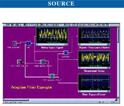
[image:4.595.60.274.318.500.2]SOURCE
Figure 3–Extracting Noise
The second implementation of adaptive filter is adaptive noise cancellation. In this case, the desired signal is the noise signal. As can be seen above in Figure 3, the Sine Generator provides a 300 Hz signal with a sample rate of 8000 Hz. The Noise Generator provides a noise signal which is effectively white noise. The two signals are added together using the add block. The resulting signal, as shown in the top left display, is connected to the first connection of the Adaptive Filter (LMS) block. Two Adaptive Filter (LMS) blocks are again cascaded to improve the filtering.
The subtract block performs the subtraction of the output of the second Adaptive Filter (extracted noise, shown in the middle right display) from the original noisy signal. The
top right display shows the final recovered signal after subtracting the estimated noise signal; it can be seen that the adaptive filtering in this case has been helpful in reducing the overall noise. In actual implementation, selection of the
‘desired’ signal is not as simple as shown here but it is quite
important and can be the make-or-break factor in an adaptive design.
APPLICATIONS
Because of their robust performance in the unknown and time-variant environment, adaptive filters have been used widely in telecommunication, radar, sonar, control, and image processing applications.
In the first example, a tone was extracted and could have been removed from the original signal; this could be quite useful for eliminating 60 Hz hum since it is so common on AC powered products. In addition, many communication systems may induce particular interfering periodic signals which are not wanted; adaptive algorithms may be used to reduce or eliminate these signals.
The second example showed a simple case of unwanted noise in a signal which is common to many systems, especially communication systems. Other systems such as automotive (both the internal [quiet environment for driver], and external such as adaptive noise cancellation for a new type of engine muffler) could benefit from adaptive filter methods.
Adaptive filter methods are not even limited by one-dimensional processing. Digital Image Processing applications could also make use of these methods. The flexibility of this powerful technique combined with the fast real-time
capabilities of today’s DSPs allow its uses to be limited only
to the creativity of the engineer
REFERENCES:
1. C. Britton Rorabaugh, DSP Primer, McGraw-Hill, 1999
3. Richard J. Higgins, Digital Signal Processing in VLSI, Prentice-Hall.
4. Bellanger, M. (2001). Adaptive Digital Filters(Second edition). Marcel Dekker, ISBN 0-8247-0563-7, New York 1990.
5. Shoval, A. ; Johns, D., & Snelgrove, W. (1995). Comparison of DC Offset Effects in Four LMS
Adaptive Algorithms, IEEE Transactions on Circuits and Systems-II: Analog and Digital Signal Processing; Volume 42, No. 3, (March 1995), pp. 176- 185
6. Shoval, A. ; Johns, D., & Snelgrove, W. (1995). Comparison of DC Offset Effects in Four LMS
Adaptive Algorithms, IEEE Transactions on Circuits and Systems-II: Analog and Digital Signal Processing; Volume 42, No. 3, (March 1995), pp. 176- 185
7. T. Chen and H.R. Wu, “Application of partition based
median type filters for suppressing noise in
images,” IEEE Transactions Image Processing, vol. 10, no. 6, pp. 829-836, Jun. 2001.
8. F. Russo and G. Ramponi,” A Fuzzy filter for images
corrupted by impulse noise,” IEEE Signal processing Letters,
vol. 3, no. 6, pp. 168-170, 1996
9. D.R.K Brownrigg, “The weighted median filter”,
Communications of the ACM, vol. 27, no. 8, pp.
807-818, August 1984
10. S. J. KO and Y. H Lee, “Center Weighted Median Filters
and Their Applications to Image
Enhancement,” IEEE Transactions on Circuits and Systems,
Vol. 38, No. 9, pp.984-993, Sep. 1991.
AUTHORS BIOGRAPHY:
Mr.S.Kiran Babu Obtained his B.E in
ECE from MVSR Engineering
College,,Hyderabad. and M..E.from Osmania University,Hyderabad.
He is having more than 10 years experience in teaching and Industrial Experiance. His research areas and publications include Advance communication, signal processing, and Digital Signal Processing.
T.Venkata KrishnaMoorthy
is an Assistant Professor in Department of ECE, Holymary
Institute of Technology and
Science. He has a total Teaching Experience of 5 years. His interest
include Teaching, signal
Processing, Image Processing. His research Areas are Adaptive Processing for Images and Video signals. . He is a life member of ISTE(India).