A Multiband MIMO Microstrip Patch Antenna for
Wireless Applications
Nagaraj Hanchinamani1, Dr. C.R. Byrareddy2 1
Ph. D Scholar, Department of Electronics Engineering Jain University Bangalore, India
2
Professor, Department of Electronics & communication Engineering BIT Bangalore, India
Abstract- This letter presents the design of a compact size modified rectangular shaped microstrip line feed with DGS patch antenna is proposed here. DGS structure is used for improving the performance of microstrip patch antenna. The proposed compact size microstrip antenna consist of a microstrip feed line on one side of the substrate with defective ground structure with rectangular slot, other side of ground plane. The parameters of proposed antenna like returns loss, VSWR, radiation pattern, gain are simulated and analyzed using CST Microwave studio suit 2015. The antenna system resonates at 9.256GHz for VSWR=1 and their 2x1 MIMO implementation for wireless applications. The antenna system operates four frequency ranges such as 7.14-7.42GHz, 7.6-8.2GHz, 8.2-8.6GHz, 9.8-10.2GHz frequencies for VSWR≤2. A study was performed to implement this antenna in 2x1 MIMO arrangements on the same circuit space with orthogonal polarization. The proposed antenna have Better mutual coupling and better envelope correlation coefficient are achieved.
Keywords—Multiple Input Multiple Outputs (MIMO);, Defective Ground structure(DGS), VSWR.
I. INTRODUCTION
Recently, demand on wireless communication has been rapidly increasing resulting in deployment of modern wireless communication systems such as Wi-Fi, WiMAX, and 3G/4G. Along with these applications, modern antennas are required to have small size and light weight. Antenna [1] is a transducer which transmits or receives electromagnetic waves. Microstrip antennas have several advantages over conventional microwave antenna and therefore are used in a variety of practical applications. Microstrip antenna was first introduced in the 1950s. However, this concept had to wait for about 20 years to be realized after the development of the printed circuit board (PCB) technology in the 1970s. microstrip antennas are the most common types of antennas with wide range of applications due to their apparent advantages of light weight, low profile, low cost, planar configuration, easy of conformal, superior portability, suitable for array with the ease of fabrication and integration with microwave monolithic integrate circuits (MMICs).
Multiple transmit and multiple receive antennas has emerged as one of the most significant technical breakthroughs in next generation wireless communications. MIMO is the use of multiple antennas at both the transmitter and receiver to improve communication performance. MIMO technology has attracted attention in wireless communications, because it offers significant increases in data throughput and link range without requiring additional bandwidth or transmit power, higher spectral efficiency and reduced fading. Because of these properties, MIMO is an important part of modern wireless communication standards such as IEEE 802.11n (Wifi), IEEE 802.16e (WiMAX), 3GPP Long Term Evolution (LTE), 3GPP HSPA+, 4G and 5G systems to come. In today’s environment, technology demands antennas which can operate on different wireless bands and should have different features like low cost, minimal weight, low profile and are capable of maintaining high performance over a large spectrum of frequencies. In this paper microstrip patch antenna array are used, because of its attractive features of low profile, light weight, small size, low cost, easy fabrication [1]. Two modified rectangular shaped radiating patch element are arranged perpendicularly to each other on one side of the substrate, other side on which some rectangular defective ground structure[5-8] and their 2x1 MIMO
implementation proposed which can be operated frequency range 7.14-7.42GHz, 7.6-8.2GHz, 8.2-8.6GHz, 9.8-10.2GHz frequencies
for VSWR≤2, ECC less than 0.01; Mutual coupling is less than -10 dB. The antenna design is simulated using the CST microwave
suit 2015. In section 2, the proposed antenna geometry is presented and in Section 3 the results are presented. The final conclusion of the paper is given in Section 4.
II. ANTENNA DESIGN
16mm × 4 mm with height (hf) of 0.1 mm. In order to improve the Bandwidth and Return loss, ground is defected with square-Shape slot. The dimension of slot along Y-axis is 3.5×5.5×11.3 mm and the dimension of slot along X-axis is 6.5×5.5×5mm. Also this slot made on ground helps in the reduction of overall weight and size of proposed antenna. The Proposed antenna resonates at frequency (fr) of 9.32GHz. The designed front view and back view single geometry of proposed patch antenna shown in fig.1, and fig.2 respectively
[image:3.612.117.490.177.285.2]
Fig.1Geometryof proposed patch anteena front view Fig.2 Geometry of proposed patch anteena back view
Table 1 shows some common design parameters or specifications for proposed antennas
Table 1 Common design specifications of antennas
Sl.No
Parameters Dimensions are in
mm/values
1 Ground
(Lg×Wg×Wg1xWg2×hg)
20×19×1×1×0.1
2 Substrate (Ls×Ws×hs) 38×40×1.6
3 Patch (Lp×Wp×hp) 19.5×20 × 0.1
4 Feed (Lf×Wf×hf) 16×4 ×0.1
5 Permittivity of substrate
material FR4
4.4
6 Step 1(Ws1×Ls1) 1.5×1.5
7 Step 2( Ws2×Ls2) 1×1
8 Slot on patch(X1×Y1×h1×t1,
X2×Y2×h2×2)
6.5×5.5×5×0.4,3.5× 5.5×11.3×0.2
9 Slot on ground plane(Wc×Lc) 3.8×2.7
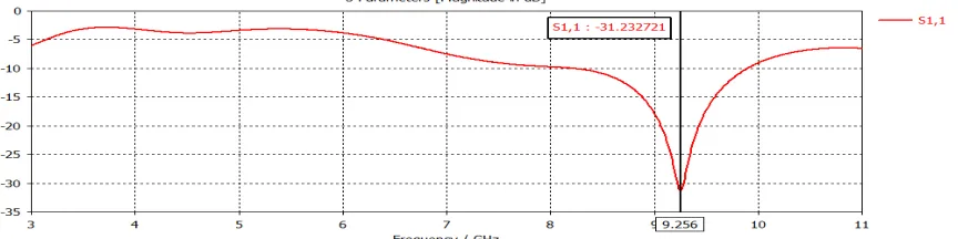
The simulation results of the return loss of the proposed antennas are shown in fig. 3 from the figure we can conclude that the
proposed patch antenna system resonates at 9.256GHz for VSWR=1. The proposed modified rectangular shapedpatch antenna is
much suitable for MIMO system. The VSWR of proposed antenna is less than 2 over entire operating frequency range. The VSWR plot of the proposed antenna is shown in fig.4
[image:3.612.171.442.346.539.2] [image:3.612.90.522.596.704.2]Fig .4 VSWR of proposed patch antenna
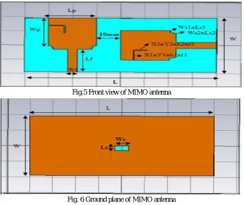
In MIMO system the major issue faced by the designer is mutual coupling, which occurs due to the electromagnetic interactions between the antennas in the array, this problem mainly arises due to the small space between antennas. The mutual coupling can be reduced by using diversity techniques which is mentioned in [8] Here a two 2x1 MIMO antenna is designed by using proposed
modified rectangular shaped patch antenna with element are arranged perpendicularly to each other same substrate with dimension
[image:4.612.131.483.325.621.2]80mm×40mm×1.6mm. Front view of MIMO antenna shown Fig. 5 and Ground plane of MIMO antenna is shown in fig.6.
Fig.5 Front view of MIMO antenna
Fig. 6 Ground plane of MIMO antenna
III. RESULTS AND DISCUSSION
The proposed modified rectangular shaped patch microstrip patch antenna is designed using a CST Microwave studio suit 2015
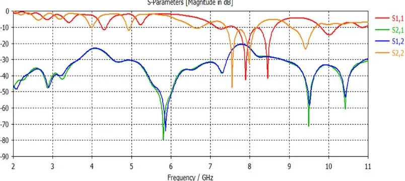
which works on principle of FIT (Finite Integration Technique). The simulation results of the return loss of the proposed MIMO
antennas are shown in Fig. 7 from the figure we can conclude that the proposed antenna operate in multiband frequency range
7.14-7.42GHz, 7.6-8.2GHz, 8.2-8.6GHz, 9.8-10.2GHz frequencies for VSWR≤2 The VSWR of the proposed antenna is presented in the
Fig.8. The radiation patterns of the MIMO antenna are shown in Fig.9, Fig.10, Fig.11, Fig.12, Fig.13, Fig.14 for the frequencies
Fig. 7 Scattering parameters of proposed MIMO antenna
Fig.8 Frequency versus VSWR of proposed MIMO antenna
Fig .11 radiation pattern of mimo antenna 8.4 GHz(1) Fig .12 radiation pattern of mimo antenna 8.4 GHz(2)
Fig .13 radiation pattern of mimo antenna 10GHz(1) Fig .14 radiation pattern of mimo antenna 10GHz(2)
The envelope correlation coefficient (ECC) is decisive parameter as it indicates the diversity performance. Computed ECC of the proposed MIMO antenna shown in fig.15. Generally a value of ECC below 0.1 is good enough to maintain channel capacity. The proposed two elements MIMO antenna provides very low correlation coefficients less than 0.005 in the overall frequency range.
Fig. 15 Computed ECC of proposed MIMO antenna
IV. CONCLUSION
In this paper presents the design of a compact size modified rectangular shaped microstrip line feed with DGS patch antenna and
their 2x1 MIMO implementation for wireless applications. The proposed antenna operate frequencies range 7.14-7.42GHz,
[image:6.612.116.498.532.644.2]dB. The proposed Antenna have Better mutual coupling and better envelope correlation coefficient are achieved.
REFERENCES
[1] C. A.Balanis “Antenna Theory, Analysis and Design” john wiley & sons, inc, new York 1997.
[2] P. Tilanthe1, P. C. Sharma, and T. K. Bandopadhyay “A Monopole Microstrip Antenna With Enhanced Dual Band Rejection for UWB Applications” Progress In Electromagnetic Research B, Vol. 38, 315{331, 2012
[3] Navya Nanda, Monika Aggarwal “Analysis and Design of Microstrip Patch Antenna with Defected Ground Structure”. International Journal of Engineering Research &Technology (IJERT),Vol. 3 Issue 6, June – 2014
[4] Rushabh Ppatel and Sanyog Rawat “Bandwidth Improvement Using Four Slots In Octagonal Microstrip patch Antenna”, Proc. of the international conference on advance in electronics, Electrical and computer science engineering ,EEC-2012.
[5] Ayman A. R. Saad, Elsayed E. M. Khaled, and Deena A Salem “Wideband Slotted Planar Antenna with Defected Ground Structure” PIERS Proceedings, Suzhou, China, September 12-16, 2011.
[6] Rajasree Hazra, Chandan Kumar Ghosh and S.K. Parui “Mutual coupling reduction between Closely spaced Microstrip patch elements using DGS” Journal of Academia and Industrial Research (JAIR) Volume 2, Issue 2 July 2013.
[7] Sukhdeep Kaur, Neha Ahuja, “Design of Microstrip patch Antenna using Defected Ground Structure for WLAN Band,” International Journal of Computer Applications (0975 – 8887) Volume 67– No.15, April 2013.
[8] A.A. Asaker, R.S. Ghoname, A.A. Zekry, “ Design of a Planar MIMO Antenna for LTE- Advanced” International Journal of Computer Applications (0975 – 8887) Volume No. 12, April 2015.
BIOGRAPHY
NAGARAJ HANCHINAMANI was born in Karnataka, India in 1988. He received the B.E Degree in Electronics and Communication engineering and the M.Tech degree in Digital Communication and Networking from the Visvesvaraya Technological University, Belgaum in 2010 and 2012 respectively. He is currently working as Lecturer in Electronics & Communication engineering department at Government Polytechnic Bankapura, Haveri. He is pursuing PhD at Jain University Bangalore. His research interest is on Antennas design and Wireless communication.