Form-finding of Bionic Structures Using the Force
Density Method and Topological Mapping
Anastasiia Moskaleva1,*, Manuel Alejandro Fernandez Ruiz2, Luisa María Gil Martín3, Aleksandra Frolovskaia4, Sergei Gerashchenko1, Enrique Hernandez-Montes3
1
School of Architecture and Design, Siberian Federal University, Russia
2
Department of Industrial and Civil Engineering, University of Cádiz, Spain
3
Department of Structural Mechanics, University of Granada, Spain
4
School of Engineering and Construction, Siberian Federal University, Russia
Copyright©2019 by authors, all rights reserved. Authors agree that this article remains permanently open access under the terms of the Creative Commons Attribution License 4.0 International License
Abstract
This article presents the results of the application of a new form-finding tool for creating free-form compression-only shell structures. This tool is based on the force density method together with topological mapping. The great advantage of this design tool is that it unifies the creative process of design, form-finding, and analysis of the compression structure and allows creating well-conceived structures. The main advantage of the use of topological mapping is that no initial shape is needed but only the coordinates of the supports. The article presents the algorithm for generating compression structures using this powerful tool and a few resulting shells of different shape, span and material (steel-and-glass, concrete, Catalan vault) received using this algorithm.Keywords
Form-finding, Compression Structures, Force Density Method, Topological Mapping, Shell Structures1. Introduction
Finding the form of shell structures had always been a challenge for designers and engineers. Since ancient times, such shapes as vaults and domes played an outstanding part in architecture and urban design. Approaches to the design of shell structures differed a lot during the history of architecture and engineering. Nowadays there is a broad variety of shell structures designed using various materials, such as steel or timber grid-shells, cable nets, reinforced concrete or masonry. It is difficult to cover all the history of shells’ design, but in general, the methods of form finding can be divided into two groups: when the form of a surface is created based on mathematically defined geometries, and when it is found based on the laws of equilibrium. This
differentiation was offered by Klaus Linkwitz [1] and it is used in this article.
The first approach to creating shells, which is based on analytical or “geometric” forms, has reached its blooming period in the 1930s, when engineers like Pier Luigi Nervi, Felix Candela, Eduardo Torroja and Anton Tedesko started to design and construct their incredibly elegant concrete thin shell structures. A huge variety of shapes and structures created based on geometric forms can be found in [2]. Fig 1 presents some examples of different forms which can be defined mathematically [2].
[image:1.595.309.531.454.532.2]a b c
Figure 1. a) Oblique helicoid; b) Surface of translation of circle along parabola; c) Elliptic paraboloid. Figures extracted from [2]
Form-finding of the structures based on the equilibrium of forces is a process based on other principles than the one described above. The main aim of this approach is to avoid bending moments in the shell, which can lead to the collapse of the structure. For a long time, the only way to create shell structures in equilibrium was physical modeling (for example, hanging models). The main idea of form finding of structures in equilibrium is the law of the hanging chain, which was formulated by Robert Hooke in the second of his ten ‘Inventions’ in 1676, and transcribed by Richard Waller in 1705:
Ut pendet continuum flexile, sic stabit contiguum rigidum inversum.
(As hangs the flexible line, so but inverted will stand the rigid arch.)
great architects as Antonio Gaudi (1852–1926), Heinz Isler (1926–2009), Frei Otto (1925-2015) and others. The analysis of the 6th Century AD arch of Taq-i Kisra carried out by Hernández Montes et al [3] showed that this law was known from the ancient times and used for creating the most effective arches and vaults. The arch of Taq-i Kisra is the largest single-span vault of unreinforced brickwork remaining in the world, and its shape is a catenary, which was analytically described more than eleven centuries after its construction.
The Spanish architect Antonio Gaudí (1852–1926) was not the first who used hanging models in his work, but the one who brought them to a new level. He applied them to unify the process of design and structural analysis from the very beginning, using both two- and three-dimensional hanging models made with strings and bags of sand to help establish the forms of his arches and vaults. He used the results of his hanging model tests as a support for his calculations and graphical static methods to determine the shape of tree-like columns and arches that defined his unique architectural style [4].
Heinz Isler (1926–2009) was one of the innovative architects and engineers of the 20th century who created concrete shell structures. He is considered one of the most important shell engineer and the creator of a new approach to design free-form shell structures [5]. As Antonio Gaudi, he used the Hooke’s law for creating his hanging shell structures, bringing them into three dimensions with the idea of the hanging chain (see Fig. 2).
Figure 2. The hanging membrane, once hardened, is inverted to create a shell form in pure compression. Extracted from [13]
Frei Otto (1925-2015), the founder of the famous Institute of lightweight structures at the University of Stuttgart, is one of the largest authorities in the field of tension structures and light-weight membranes. His team’s work has spearheaded advances in structural mathematics and civil engineering. Moreover, he explored a great number of physical form-finding techniques, from hanging models to soap models. His professional path was far from the traditional methods of calculating forces [6]. Another field of research interests of Frei Otto was form-finding of light-weight shells which could be formed using the Hookean principle of inverting a hanging net (Fig. 3).
Great research work in experimental methods of form-finding of tension structures was done in the Institut fur Leichte Flachentragwerke (directed by F. Otto) at the University of Stuttgart. The results of this work were
applied in the construction of the cable net structures of the Olympic stadium in Munich, and many others [7]. While working on the project ‘Olympic Roofs’ it became more and more evident that experimental methods have a number of limitations, and design of large-spanned structures requires new tools for the analytical computation of equilibrium shapes. This project had a lot of challenges, and to solve them, a number of breakthrough solutions were found. Linkwitz and Shek introduced the concept of force densities, which was a starting point for the discovery and formulation of the force density method [8].
Figure 3. Hanging chain model for the multipurpose hall building in Mannheim. Extracted from [8]
Nowadays different computational methods based on the principle of hanging chain are developed. The most commonly used methods are the force density method (FDM) [1, 8], thrust network analysis (TNA) [9, 10] and dynamic relaxation method [11, 12]. A deep and detailed analysis of different methods and approaches of form-finding was made by F. Block at al. [13].
Another direction of research related to the form-finding problem is topology optimization (the process that allows reducing the mass and improving the stiffness characteristics of structures). This term refers to changes in the design, including the creation of the new boundaries of the body and the removal of existing ones. The goal of topology optimization is to increase or decrease a given property of a structure (for example, to reduce the deformation energy) while satisfying certain conditions (for example, to reduce material consumption). H. Ghasemic et al. [14] suggest a design methodology based on a combination of isogeometric analysis (IGA), level set and point wise density mapping techniques for topology optimization of piezoelectric/flexoelectric materials. N. Vu-Bac et al. [15] have developed a new method which combines NURBS-based inverse analysis with material and geometric nonlinearities to identify the unknown applied loads from given displacements and reconstruct the deformations of thin shell structures.
[image:2.595.308.535.219.363.2] [image:2.595.60.287.436.529.2]beginning and as a result allows getting well-conceived structures, attractive and effective from both the architectural and structural points of view.
2. Methods
2.1. Force Density Method
[image:3.595.96.295.356.554.2]The force density method was presented by Linkwitz and Schek in 1971 [16]. The main advantage of the FDM is that it is a linear method. The core of this method is a description of the equilibrium state of any general pin-jointed network using coefficients called force: length ratios or force densities [17]. Another important advantage of the FDM as a form-finding method is that there is no need for information about the geometry of the structure in the design process. The starting point for the FDM is a pin-jointed network consisting of cable or bar elements connected by nodes, in which some of the points are fixed and the others are free. The free points will have to find a position in the equilibrium configuration [18].
Figure 4. Example of branch-node matrix [16]
1
0
1
0
0
0
1
1
0
1
1
0
C
−
=
−
−
(1)For a given pin-jointed network with n nodes and m
branches (Fig. 4), the branch-node matrix C is an m×n
matrix used in the FDM to define the connectivity of the nodes. As shown in Fig. 4 and Eq. 1, each branch or connection j links two nodes i(j) and k(j). For i<k the elements of the branch-node matrix C can be defined as follows:
1 if i(j)=r
( , )
1 if i(j)=r
0 for the rest
C j r
+
= −
(2)The nodes Pi have coordinates (xi, yi, zi) , i=1, . . . , n. The fixed nodes with known coordinates will constitute the input data for the initial equilibrium configuration problem. The x, y, and z coordinates for each of the nodes can be
grouped in the n vectors x, y, and z. The m vector l contains the lengths lj of each branch j, and the vector s is the m
vector formed by the branch forces sj of each branch j. The
nodal loads are characterized by means of n vectors p containing the force components px, py, and pz. According
to this, the equilibrium equations for each node now can be stated. The projections of the forces in the node 3 (Fig. 4) along each one of the axes gives the following equilibrium equations:
3
1 2
3 1 3 4 3 2 3
1 2 3
3
1 2
3 1 3 4 3 2 3
1 2 3
3
1 2
3 1 3 4 3 2 3
1 2 3
( ) ( ) ( ) ( ) ( ) ( ) ( ) ( ) ( ) x y z s s s
x x x x x x p
l l l
s
s s
y y y y y y p
l l l
s
s s
z z z z z z p
l l l
− + − + − =
− + − + − =
− + − + − =
(3)
The key contribution of the FDM is the introduction of a force density coefficient q, which is defined as the force-length ratio for the branches of the network. If q is constant then the equilibrium equations become a linear system [16].
For a more general formulation of FDM, the coordinate differences of u, v, and w related nodes are considered.
These are m vectors that can be obtained using the C matrix:
u
Cx
v
Cy
w
Cz
=
=
=
(4)Given that the matrices U, V, W, and L as diagonal matrices resulting from the placement of the vectors u, v, w, and l in the main diagonal, the equilibrium equations for the entire network can be given in the following form:
1
1
1
(
)
0
(
)
0
(
)
0
t x t y t z
C UL
s
p
C UL
s
p
C UL
s
p
− − −
+
=
+
=
+
=
(5)The key advantage of the force density method is that the above system of equations is linear under the following
suppose:
1
q
=
L s
− (6)Where q = m is a vector containing the force-density ratios qj of all branches. Finally, given the following identities:
Uq
Qu
Vq
Qv
Wq
Qw
=
=
=
(7)equilibrium equations follow from this:
(
)
0
(
)
0
(
)
0
T
x
T
y
T
z
C QC x
p
C QC y
p
C QC z
p
+
=
+
=
+
=
(8)
The aforementioned system of equations is a linear system, where the known values are the coordinates of the fixed points, the topology of the pin-joined network and the force density ratios. Unknowns are the coordinates of the unfixed nodes. Therefore, the matrix that defines the connectivity of the nodes of the network (C) is another important input in FDM. Topological mapping (TM) is a method used to generate a general network of the structure and to define the connectivity matrix C as suggested by E. Hernández-Montes et al [18].
The FDM was originally used for tension structures. If the purpose is to create a compression-only structure, the method has to be modified. Hernández-Montes et al. [19] proposed a form-finding method based on FDM&TM, similar to the physical hanging models employed by Antonio Gaudi. A tension structure is created, then the equilibrium position is found and finally the structure is turned upside down. By doing so, all the elements which were in tension are in pure compression in the inverted structure, and the bending moments are minimal or negligible.
2.2. Topological Mapping
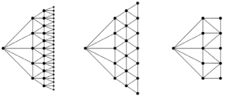
[image:4.595.307.539.436.608.2]Topological mapping was suggested by Hernández-Montes et al. [18] among other methods to define the connectivity matrix C for the force density method. It is based on the idea that to create a network structure by the FDM, there is no need to have information about the position of all points of the network structure, except for the support points and a few algorithms that define the connectivity between the rest of the nodes. Three different types of networks can be created by this method. Types A, B and C are shown in Fig. 5.
Figure 5. Three types of network generated by TM (types A, B and C). Extracted from [16]
TM constructs the topological mesh by means of successive steps or rings, from the following inputs:
a. Number of nodes in the first step b. Number of total steps
c. Topological relation between successive steps d. Type or network to be created— open or closed. A complete and detailed description of the topological mapping approach can be found in [18] and [19].
2.3. Creating Bionic Structures by TM-FDM: Opportunities for Architects and Engineers
Based on the force density method and topological mapping the GAUDI software [20] was suggested as a new form-finding tool for compression structures. It is based on constant values of the force: length ratios that give endless opportunities for creativity for architects and engineers. The FDM itself is a method where the processes of design and structural analysis are integrated. The main advantage of the FDM is that it linearizes the form-finding problem. The new software allows to introduce external loadings as the self-weight that changes as the shape changes, then the process of form-finding is solved by iterations.
It allows to find the equilibrium shape of a structure initially desired by an artist by iteratively changing input parameters. The following procedure was used to obtain the final structure:
The first step is defining the initial shape in the ground plan and the coordinates of the anchor points (supports) (Table 1). It is important to number the points in the right order (clockwise).
Table 1. Coordinates of anchor points
Xi(m) Yi(m) Zi(m)
3,5 3,5 3,5
0,0 0,0 0,0
3,5 3,5 3,5
3,5 3,5 3,5
7,0 7,0 7,0
10,5 10,5 10,5
10,5 10,5 10,5
14,0 14,0 14,0
10,5 10,5 10,5
10,5 10,5 10,5
The second step is to define the material of the structure. Depending on the material it is necessary to insert the own weight of the structure. Then the number of rings and the type of topology for each ring is defined. This process of finding a proper shape of the structure is iterative, depending on the boundary conditions and the initial concept of the designer (Table 2 and 3).
The definition of the force: length coefficients for branches is also an iterative process. The program allows the definition of the force: length coefficients for the branches of each ring (qa) and for radial branches (qr)
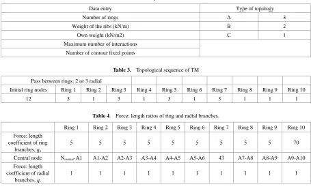
[image:4.595.61.287.576.676.2]Table 2. Some of the inputs for the software Gaudí
Data entry Type of topology
Number of rings A 3
Weight of the ribs (kN/m) B 2
Own weight (kN/m2) C 1
Maximum number of interactions Number of contour fixed points
Table 3. Topological sequence of TM Pass between rings: 2 or 3 radial
Initial ring nodes Ring 1 Ring 2 Ring 3 Ring 4 Ring 5 Ring 6 Ring 7 Ring 8 Ring 9 Ring 10
12 3 1 3 1 3 1 3 1 1 1
Table 4. Force: length ratios of ring and radial branches.
Ring 1 Ring 2 Ring 3 Ring 4 Ring 5 Ring 6 Ring 7 Ring 8 Ring 9 Ring 10 Force: length
coefficient of ring branches, qa
5 5 5 5 5 5 5 5 5 70
Central node Ncentral-A1 A1-A2 A2-A3 A3-A4 A4-A5 A5-A6 43 A7-A8 A8-A9 A9-A10
Force: length coefficient of radial
branches, qr
1 1 1 1 1 1 1 1 1 1
If the design of the structure implies ribs, it is possible to create them by choosing branches that form them and assigning higher force: length coefficients to them. The advanced research on the topic of adding inner and outer ribs can be found in [21].
3. Results
Nature was always a source for inspiration for both architects and engineers, not only from the point of view of the beautiful appearance but also as a source of conceptual approaches for creating new technologies (great engineers as Frei Otto, Eduardo Torroja and Felix Candela took their inspiration from nature) [22]. A number of free-form shell structures inspired by different bionic forms were created using the GAUDI software and the described procedure. The results of this work are presented in the catalogue “Topological design of bionic structures: inspired by nature” which is available on the website of the University of Granada [23]. In this section, some of these shell structures are described in detail. The structures are considered to be made of three different materials: masonry (Catalan vault technique), concrete, and a grid shell of steel
and glass.
3.1 The Seashell Structure
The first structure, inspired by the seashell, is designed of masonry, has 6 anchor points and the maximum height of about 1.206 m. The input data is shown in Table 5. The coordinates of support points are given in meters. As the material of the structure is masonry, the self-weight and weight of the ribs is defined as the weight of masonry. The resulting structure can be seen in Fig. 6.
Table 5. Input of the Seashell structure
Input data Coordinates of anchor points Number of rings 10 X
i(m) Yi(m) Zi(m)
Number of nodes in initial ring 6 1,0 0,0 0,0 Number of contour anchor
points 6 3,0 0,0 0,0
Weight of ribs (kN/m) 0,23 4,0 1,73 0,0 Self-weight (kN/m2) 1,0 3,0 3,46 0,0
[image:5.595.69.525.87.367.2]Figure 6. The Seashell structure, values of the force: length coefficient of radial and ring branches shown in color.
Table 6. Force: length ratio values of the Seashell structure
Ring 1 Ring 2 Ring 3 Ring 4 Ring 5 Ring 6 Ring 7 Ring 8 Ring 9 Ring 10
Type of topology A A C C A C C A C C
Force: length coefficient of ring branches 0,7 0,7 0,6 0,6 0,5 0,5 0,6 0,5 0,6 0,6 Force: length coefficient of radial branches 0,15 0,13 0,13 0,11 0,1 0,1 0,1 0,1 0,1 0,12
The designed structure was generated after a number of iterations, which led to the final configuration with the parameters shown in Table 6. In the first line, the types of topology for each ring are shown. The second and third lines of Table 6 show the values of the force: length coefficient of ring and radial branches. This pattern based on the types of topology and values of force: length coefficients allowed to get theunique configuration of the equilibrium shape of the structure presented in Fig.6 with the maximum height of 1,206 m.
3.2. The Nautilus Shell Structure
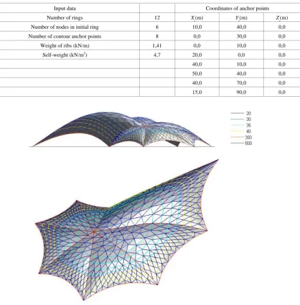
The second structure, inspired by Nautilus shell, was designed of concrete and with a larger span than in the first shell. The purpose was to compare the difference in force: length coefficients depending on the size and material of the structure. The input data for the Nautilus shell structure are shown in Table 7 and the resulting shell is presented in Fig.7.
From Table 8 we can see that the force: length ratio values of this structure are higher than in the previous one. The reason is that the self-weight of concrete is considerably higher than the weight of masonry, and a larger span also leads to higher force: length coefficients.
3.3. The Flower Structure
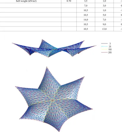
Another model of the shell, inspired by the flower shape, is a spatial grid structure made of steel and glass. As the software does not allow inputting different weights for branches and triangles, the average value of self-weight was taken (see Table 9). The resulting model is shown in Fig.8.
[image:6.595.148.443.83.347.2]Table 7. The input data for the Nautilus shell structure
Input data Coordinates of anchor points
Number of rings 12 X
i(m) Yi(m) Zi(m)
Number of nodes in initial ring 6 10,0 40,0 0,0
Number of contour anchor points 8 0,0 30,0 0,0
Weight of ribs (kN/m) 1,41 0,0 10,0 0,0
Self-weight (kN/m2) 4,7 20,0 0,0 0,0
40,0 10,0 0,0
50,0 40,0 0,0
40,0 70,0 0,0
15,0 90,0 0,0
Figure 7. The equilibrium shape of the Nautilus shell structure with the values of the force: length coefficient of radial and ring branches shown in colour
Table 8. Force: length ratio values of the Nautilus structure Ring
1 Ring
2 Ring
3 Ring
4 Ring
5 Ring
6 Ring
7 Ring
8 Ring
9
Ring 10
Ring 11
Ring 12
Type of topology A B A B A B A B B B C C
Force: length coefficient of ring
branches 30 30 30 30 35 35 35 35 40 40 40 350
Force: length coefficient of radial
[image:7.595.85.524.88.533.2] [image:7.595.67.527.581.661.2]Table 9. The input data for the Flower structure
Input data Coordinates of anchor points
Number of rings 10 Xi(m) Yi(m) Zi(m)
Number of nodes in initial ring 6 3,5 9,0 0,0
Number of contour anchor points 12 0,0 7,0 -1,5
Weight of ribs (kN/m) 0.50 3,5 5,0 0,0
Self-weight (kN/m2) 0.70 3,5 1,0 -1,5
7,0 3,0 0,0
10,5 1,0 -1,5
10,5 5,0 0,0
14,0 7,0 -1,5
10,5 9,0 0,0
[image:8.595.99.494.173.598.2]10,5 13,0 -1,5
Figure 8. Flower structure with the values of the force: length coefficient of radial and ring branches shown in colour
Table 10. Force: length ratio values of the Flower structure
Ring 1 Ring 2 Ring 3 Ring 4 Ring 5 Ring 6 Ring 7 Ring 8 Ring 9 Ring 10
Type of topology А B B B A B B B B B
4. Conclusions
The article presents the results of applying a new powerful tool to design complex compression-only structures made of different materials with inner ribs. The force density method together with topological mapping (TM-FDM) opens great opportunities for creativity for architects and engineers in the field of creating compression shell structures. The roots of this approach and the experience of great architects were analyzed.
The steps of generating process presented in the article show that the process is iterative from the very beginning, and allows to obtain any shape considered by an artist if this shape responds to the laws of equilibrium.
The analysis of the results shows the difference in values of the force: length coefficient depends on the material and scale of a structure.
The values of the force: length ratios of the ring branches of the Seashell structure are around 0.5, of radial branches are 0,1 (Table 6).
The scale of the Nautilus shell structure is around 70 meters and the material is concrete. The average value of force: length coefficients of the ring branches is 35, of radial branches is 20 (see Table 8).
The Flower structure is designed in steel and glass with a span of around 10 meters. The value of the force: length coefficients of the ring branches is 5, of the radial branches is 1.
Thus the Seashell structure has the minimal values of the force: length coefficients, less than 0. It can be explained by the dependence of this coefficient on the overall weight of the structure. The self-weight of masonry is significantly lower than the self-weight of concrete (Tables 5 and 9), so the difference between the coefficients is really noticeable. The same is true for the Flower steel-and-glass structure. The self-weight of the grid with steel branches and glass triangles is about 0.70kN/m2. This value is a great deal lower than the self-weight of masonry and concrete. The force: length coefficients for the Flower structure are lower than the ones for concrete but higher than those for masonry. But the span of the Flower structure is considerably larger than the one of masonry, so its overall weight is also higher.
In conclusion, it can be noted that there are different principles of form finding of shell structures. Architects and engineers determine the method which is the most suitable for the particular case by a number of parameters, such as the material of the structure, the main idea of design, boundary conditions, etc. The article describes some practical applications of a tool for design of free-form shell structures in equilibrium, which is based on previous works related to the topological mapping (TM) and the force density method (FDM). The GAUDI software allows to create various structures of different materials, and the main advantage that the resulting shape is a shell with minimal bending moments. This means that such structures
are cost-effective, although each of them can have its own unique form. Therefore, including them to the city environment can contribute a lot to the attractiveness of the place, with not very high investment and labor costs.
REFERENCES
K. Linkwitz. About form finding of double-curved [1]
structures, Engineering Structures, Vol. 21, 709–718, 1999.
S. N. Krivoshapko, V. N. Ivanov. Encyclopedia of [2]
analytical surfaces, Springer, Switzerland, 2015.
E. Hernández Montes, L. M. Gil Martín, M. A. [3]
Fernández-Ruiz, M. Aschheim. Structural knowledge within the 6th Century AD arch of Taq-i Kisra, International Journal of Architectural Heritage, Vol. 11(6), 891-900, 2017.
B. Addis. Toys that save millions - A history of using [4]
physical models in structural design, Structural Engineer, Vol. 91(4), 12-27, 2013.
B. Peerdeman. Analysis of thin concrete shells revisited: [5]
opportunities due to innovations in materials and analysis methods, Master thesis, 2008.
I. Liddell. Frei Otto and the development of grid shells, [6]
Case Studies in Structural Engineering, Vol. 4, 39–49, 2015.
M. Eekhout. Architecture in space structures, 010 [7]
Publishers, Rotterdam, 1989.
K. Linkwitz. New methods for the determination of cutting [8]
pattern of prestressed cable nets and their application to the Olympic Roofs Munich, IASS Pacific Symposium on Tension Structures and Space Frame, Tokyo, 1971.
Ph. Block. Thrust Network Analysis: Exploring [9]
Three-dimensional Equilibrium, Ph.D. thesis, Massachusetts Institute of Technology, Cambridge, 2009.
Ph. Block, J. Ochsendorf. Thrust Network Analysis: A new [10]
methodology for three-dimensional equilibrium, Journal of the International Association for Shell and Spatial Structures, Vol. 48(3). 167-173, 2007.
M. Barnes. Form-finding and analysis of tension space [11]
structures by dynamic relaxation, Ph.D. thesis, City University London, 1977.
M. Barnes, D. Wakefield. Dynamic relaxation applied to [12]
interactive form finding and analysis of air-supported structures, Proceedings of Conference on the Design of Air-supported Structures, 147–161, 1984.
S. Adriaenssens, Ph. Block, D. Veenendaal, C. Williams. [13]
Shell structures for architecture: form finding and optimization, Routledge, New York, 2014.
H. Ghasemic, H. S. Parkd, T. Rabczuk. A level-set based [14]
IGA formulation for topology optimization of flexoelectric materials, Computer Methods in Applied Mechanics and Engineering, Vol. 313, 239-248, 2017.
N. Vu-Bac, T. X. Duong, T. Lahmer, X. Zhuang, R. A. [15]
thin shell structures, Computer Methods in Applied Mechanics and Engineering, Vol. 331, 427-455, 2018.
K. Linkwitz, H. J. Shek. Einige Bemerkung von [16]
vorsgepannten Seilnetzkonstruktionen, Ingenieur-archv, Vol. 40, Springer, Berlin, 145–158, 1971.
H. J. Schek. The force density method for form finding and [17]
computation of general networks, Computer methods in applied mechanics and engineering, Vol. 3, 115-134, 1984.
E. Hernández-Montes, R. Jurado-Piña, E. Bayo. [18]
Topological mapping for tension structures, Journal of Structural Engineering, Vol. 132(6), 970–977, 2006.
J. F. Carbonell-Márquez, L. M. Gil-Martín, M. A. [19]
Fernández-Ruíz, E. Hernández-Montes. Topological design of compression structures, Archive of Applied Mechanics, Vol. 86(8), 1495-1508, 2016.
J. F. Carbonell-Márquez, L. M. Gil-Martín, E. [20]
Hernández-Montes, R. Jurado-Piña, GAUDI 1.0–Manual de Usuario, Godel Impresiones Digitales, Granada, 2012, Online available from http://www.ugr.es/~tep190/investiga cion/gaudi.html.
M. A. Fernández-Ruiz, E. Hernández-Montes, J. F. [21]
Carbonell-Márquez, L. M. Gil-Martín. Patterns of force: length ratios for the design of compression structures with inner ribs, Engineering Structures, Vol. 148, Pp. 878–889, 2017.
J. Kim, K. Park. The Design Characteristics of [22]
Nature-inspired Buildings, Civil Engineering and Architecture, No 6(2), 88-107, 2018.
A. V. Moskaleva, B. Šćepanović, J. F. Carbonell-Marquez, [23]

![Figure 3. Hanging chain model for the multipurpose hall building in Mannheim. Extracted from [8]](https://thumb-us.123doks.com/thumbv2/123dok_us/8748292.891319/2.595.60.287.436.529/figure-hanging-chain-model-multipurpose-building-mannheim-extracted.webp)
![Figure 4. Example of branch-node matrix [16]](https://thumb-us.123doks.com/thumbv2/123dok_us/8748292.891319/3.595.96.295.356.554/figure-example-of-branch-node-matrix.webp)