ii
MOHAMED SALEH KHALIFA
A project report is Submitted In partial
Fulfillment of the Requirements for The Award of The Degree of Master of Electrical Engineering
Faculty of Electrical and Electronic Engineering University Tun Hussein Onn Malaysia
JUNE, 2015
ABSTRACT
VII
ABSTRAK
CONTENTS
TITLE II
DEDICATION IV
ACKNOWLEDGEMENTS V
ABSTRACT VI
ABSTRAK VII
LIST OF CONTENTS VIII
LIST OF TABLES XI
LIST OF FIGURES XII
LIST OF SYMBOL AND ABBREVIATIONS XV
CHAPTER 1 INTRODUCTION 1
1.1 Introduction 1
1.2 Motivation / Problem Statements of The Study 3
1.3 Aim of The Study 3
1.4 Objectives of Project 3
1.5 Project Scopes 4
CHAPTER 2 LITERATURE REVIEW 5
2.1 Introduction 5
2.2 OFDM system 6
2.2.1 Concept of OFDM 6
2.3 OFDM advantages & disadvantages 8
2.4 OFDM system model ( transmitter and receiver system in OFDM )
IX
2.4.1 Interleave and Deinterleave 9
2.4.2 Modulation and Demodulation 10
2.4.3 Cyclic Prefix Insertion 10
2.4.5 Inverse Fast Fourier Transform/Fast Fourier Transform (IFFT /FFT)
12
2.4.6 Serial to parallel Conversion 13
2.4.7 Time frequency synchronization 13
2.4.8 Quadrature Phase Shift Keying (QPSK) 13
2.5 PAPR Reduction Techniques 14
2.5.1 Signal distortion techniques 15
2.5.1.1 Clipping 15
2.5.1.2 Peak windowing 15
2.5.1.3 Peak Cancellation 17
2.5.1.4 Partial Transmit Sequences (PTS) 18
2.5.1.5 Selected Mapping 19
2.6 Previous studies
CHAPTER 3 METHODOLOGY 24
3.1 Introduction 24
3.2 Simulation Methodology 24
3.3 Introduction to Peak to Average Power Ratio (PAPR) 26
3.4 Introduction to Selected Mapping (SLM) 28
3.5 Threshold Selected Mapping 29
3.6 Power Savings through Selected Mapping 32
3.7 Value α at selected mapping 34
CHAPTER 4 RESULT AND ANALYSIS 37
4.1 Introduction 37
4.1.1 OFDM Transmitter 38
4.1.2 OFDM Receiver 39
4.1.3 The Performance Analysis 39
4.2 Threshold Selected Mapping 42
5.1 Conclusion 52
5.2 Suggestions for Future Work 53
REFERENCES 54
APPENDIX 57
XI
LIST OF TABLES
3.1 PAPR Reduction and Saving Gain Using SLM where N = 256 and X = 1, 2, 4,8,16
34
3.2 PAPR Reduction Corresponding to Various Phase Sequences for Number of Subcarriers N =128
35
LIST OF FIGURES
2.1 Spectra of OFDM individual subcarrier 7
2.2 Spectra of OFDM symbol 7
2.3 Basic OFDM system 9
2.4 OFDM signal 11
2.5 IFFT and FFT description 12
2.6 Constellation Diagram for QPSK 14
2.7 QAM Modulator 14
2.8 Amplitude of transmitted OFDM symbol 16
2.9 Windowing an OFDM time signal 17
2.10 A Block diagram of PAPR reduction by Peak Cancelation 18 2.11 OFDM symbol envelop (a) and signal envelope after peak
cancellation(b)
19
2.12 A block diagram of the PTS technique 20
3.1 Flow chart of reducing PAPR 25
3.2 Power samples of one symbol OFDM signal 27
3.3 Block diagram of SLM technique 29
3.4 PAPR Reduction for SLM where N = 128 and X = 1, 2, 4,8,16 34 3.5 Insert this data on cumulative distribution function (CDF) software 35 3.6 Value α use The Complementary Cumulative Distribution function
(CCDF)
36
XIII
function CCDF
4.1 OFDM Basic Model 37
4.2 Simulink Model of OFDM Transmitter 38
4.3 IFFT Parameters 38
4.4 Add cyclic prefix parameters 39
4.5 Simulink Model of OFDM Receiver 39
4.6 Frequency spectrum of OFDM signal 40
4.7 Transmission signal of OFDM system 40
4.8 Receiver signal of OFDM system 40
4.9 Frequency spectrum with increasing power 41
4.10 Receiver signal of OFDM system with increasing power 41 4.11 PAPR Reduction for SLM where N = 64 and X = 1, 2, 4,8,16 42 4.12 PAPR Reduction for SLM where N = 64 and X = 1, 2, 4,8,16 using
chart
44
4.13 PAPR Reduction for SLM where N = 128 and X = 1, 2, 4,8,16 44 4.14 PAPR Reduction for SLM where N = 128 and X = 1, 2, 4,8,16 using
chart
45
4.15 PAPR Reduction for SLM where N = 256 and X = 1, 2, 4,8,16 45 4.16 PAPR Reduction for SLM where N = 256 and X = 1, 2, 4,8,16 using
chart
46
4.17 PAPR Reduction for SLM where N = 512 and X = 1, 2, 4,8,16 46 4.18 PAPR Reduction for SLM where N = 512 and X = 1, 2, 4,8,16 using
chart
47
4.19 PAPR Reduction for SLM where N = 1024 and X = 1, 2, 4,8,16 47 4.20 PAPR Reduction for SLM where N = 1024 and X = 1, 2, 4,8,16 using
chart
48
4.21 PAPR Reduction for SLM where α =2.8, N = 64, and X = 1, 2, 4,8,16 48 4.22 PAPR Reduction for SLM where α =2.8, N = 64, and X = 1, 2, 4,8,16
using chart49
4.23 PAPR Reduction for SLM where α =2.8, N = 128, and X = 1, 2, 4,8,16 49 4.24 PAPR Reduction for SLM where α =2.8, N = 128, and X = 1, 2, 4,8,16
using chart
50
4.25 PAPR Reduction for SLM where α =2.8, N = 256, and X = 1, 2, 4,8,16 50 4.26 PAPR Reduction for SLM where α =2.8, N = 256, and X = 1, 2, 4,8,16
using chart
XV
LIST OF SYMBOL AND ABBREVIATIONS
ADSL Asymmetric Digital Subscriber Line BRAN Broadband Radio Access Networks
Bc Coherence Bandwidth
CCDF Complementary Cumulative Distribution Function CDF Cumulative Distribution Function
CP Cyclic Prefix
DAB Digital Audio Broadcasting DFT Discrete Fourier Transform
DVB-T Digital Video Broadcasting-Terrestrial FDM Frequency Division Multiplexing
FFT Fast Fourier Transform
HF High Frequency
ICI Inter Carrier Interference
IDFT Inverse Discrete Fourier Transform IFFT Inverse Fast Fourier Transform
ISI Inter Symbol Interference LOS Line of Sigh Path
MC Multicarrier Modulation
OFDM Orthogonal Frequency Division Multiplexing PAPR Peak to Average Power Ratio
PSK Phase Shift Keying PTS Partial Transmit Sequence
QAM Quadrature Amplitude Modulation
RF Radio Frequency
CHAPTER 1
INTRODUCTION
1.1 Introduction
Orthogonal Frequency Division Multiplexing (OFDM) is a Multi-Carrier Modulation technique in which a single high rate data-stream is divided into multiple low rate data-streams and is modulated using sub-carriers which are orthogonal to each other.
The Orthogonality of the carriers means that each carrier has an integer number of cycles over a symbol period. Due to this, the spectrum of each carrier has anull at the center frequency of each of the other carriers in the system. This results in no interference between the carriers, although their spectra overlap. The separation between carriers is theoretically minimal so there would be a very compact spectral utilization [1].
OFDM systems are attractive for the way they handle Inter Symbol Interference (ISI) which is usually introduced by frequency selective multipath fading in a wireless environment. Each sub-carrier is modulated at a very low symbol rate, making the symbols much longer than the channel impulse response.
2
1.2 Motivation / Problem Statements of The Study
Orthogonal Frequency Division Multiplexing (OFDM) is a promising technology which can be used in many applications and is an efficient method of data transmission for high speed communication systems. There are still some problems that need to be overcome. One of the main problems is the high Peak to Average Power Ratio (PAPR) of the transmitted signals. OFDM (Orthogonal frequency division multiplexing) consist of a large number of independent subcarriers, as a result of which the amplitude of such a signal can have high peak values.
1.3 Aim of The Study
Work to reduce the high Peak to Average Power Ratio (PAPR) of the transmitted signals using the Selected Mapping technique (SLM).
1.4 Objectives of Project
I. To understand and analyze the OFDM system and definition of OFDM transmitter and OFDM receiver.
II. To implement and simulate OFDM system using MATLAB software in order to have better understanding of the standard and the system performance.
4
1.5 Project Scopes
The project scopes include:
CHAPTER 2
LITERATURE REVIEW
2.1 Introduction
6
2.2 OFDM system 2.2.1 Concept of OFDM
Figure 2.1 illustrates the spectrum of an individual data subcarrier. In the individual spectra the OFDM signal equal to the bandwidth of each subcarrier. Figure 2.2 shows the spectrum of the OFDM symbol..
[image:18.612.149.513.459.668.2]Figure 2.1: Spectra of OFDM individual subcarrier
8
2.3 OFDM advantages & disadvantages 2.3.1 Advantages of the OFDM are:
The OFDM is an efficient way to deal with multipath and delay spread.
The implementation of the OFDM system is significantly lower than that of a single carrier system with an equalizer.
The OFDM is resistance to frequency selective fading. This is because such interference affects only a small percentage of the Subcarries (SC).
The bandwidth usage of the OFDM is efficient.
2.3.2 The disadvantages of the OFDM are:
The OFDM is more sensitive to frequency offset and phase noise.
OFDM has a relatively large peak-to average-power ratio, which tends to reduce the power efficiency of the radio frequency (RF) amplifier.
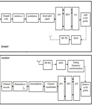
2.4 OFDM system model ( transmitter and receiver system in OFDM )
Figure 2.3: Basic OFDM system
2.4.1 Interleave and Deinterleave
All encoded data bits shall be interleaved by a block interleaver with a block size
corresponding to the number of coded bits per the specified allocation, Ncbps. Due to
different modulation scheme BPSK, QPSK, 16QAM, 64-QAM. The interleaver is
10
mapped onto nonadjacent carriers. This ensures that if a deep fade affects a bit, its
neighboring bits are likely to remain unaffected by the fade, and therefore is
sufficient to correct the effects of the fade. The second permutation insures that
adjacent coded bits are mapped alternately onto less or more significant bits of the
constellation. This makes detection accurate and long runs of low reliability bits are
avoided. Deinterleaver is performed in reverse order of operations [5] .
2.4.2 Modulation and Demodulation
After bit interleaving, the data bits are entered serially to the constellation mapper.
The specified modulation scheme in the downlink (DL) and uplink (UL) is binary
phase shift keying (BPSK), quaternary PSK (QPSK), 16 quadrature amplitude
modulation (QAM) and 64QAM to modulate bits to the complex constellation points.
The FEC options are paired with the modulation schemes to form burst profiles.
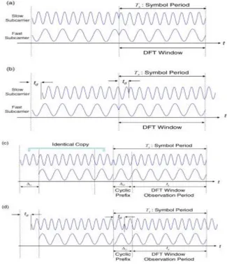
2.4.3 Cyclic Prefix Insertion
To explain the cyclic prefix for OFDM let us start by assuming two OFDM symbols
that they have experienced a delay spread td and channel dispersion. Figure 2.4a
illustrates slow subcarrier (slow delay spread at td ) and fast subcarrier (fast delay
spread at td ) inside each OFDM symbol on the transmitted signal. Figure 2.4b shows
slow subcarrier delayed by td against fast subcarrier on the received signal. As it can
be seen from the figure 2.4b that the slow subcarrier in the OFDM symbol interfere
with another OFDM symbol and that is called inter symbol interference (ISI).
Moreover, the OFDM waveform in the discrete Fourier transform (DFT) window is
incomplete so that the orthogonality condition for the subcarrier is lost which result in
inters carrier interference (ICI).
Cyclic prefix is a technique that is used to resolve ISI and ICI. Figure 2.4c shows a cyclic prefix of the OFDM symbol into the guard interval ΔG. And the
OFDM signal with guard interval on the received signal is shown in figure 2.4d. As it
can be seen from the figure 2.4d the OFDM symbol of the slow subcarrier is in the
DFT window because the cyclic prefix has moved into the DFT window to replace
the signal that has shifted out of this OFDM symbol .
Thus, the main idea of this technique is to replicate part of the OFDM
waveform from the back to the front to develop a guard period. And at the receiver,
certain position within the cyclic prefix is picked as the sampling starting point, which satisfies the condition td < ΔG where td is the delay spread and ΔG the guard
[image:22.612.179.504.270.649.2]interval [6] .
12
2.4.4 Inverse Fast Fourier Transform/Fast Fourier Transform (IFFT /FFT)
The inverse Fourier transform converts the frequency domain data stream into the corresponding time domain. Then a parallel to serial convertor is used to transmit time domain samples of one symbol. The Fast Fourier Transformation (FFT) is used to convert data in time domain to the frequency domain at the receiver. The serial to parallel block convertor is placed to convert this parallel data into a serial stream to the original input data. IFFT (Inverse Fast Fourier Transformation) block allocates the different orthogonal subcarrier for transmitted bits and thus no interference exists between subcarriers. In this situation sub-carriers can be closer together, which means that bandwidth can be saved signification [7].
2.4.5 Serial to parallel Conversion
The input serial data stream is change into the word size which is requiring for transmission and is shifted into a parallel format. The data is then being transmitted in parallel by assigning each data word to one carrier in the transmission.
2.4.6 Time frequency synchronization
In OFDM systems, the main synchronization parameters to be estimated are a sync fla indicating the presence of the signal (especially for burst-mode transmission), the starting time of the FFT window (timing synchronization), the frequency offset due to the inaccuracies of the transmitter and receiver oscilla-tors, and the Doppler shift of the mobile channel, as well as the channel estimates if coherent reception is adopted. The sync flag can be generated by automatic gain control (e.g., ramp-up indication via power measurement and threshold decision) or using a training symbol (which can also be used for timing synchronization and possibly frequency synchronization). For the latter case, the same metric used for timing synchronization may be used together with the threshold decision, in order to generate the sync flag. After detecting the presence of the signal, the other sync parameters are estimated. In the following, the effect of timing synchronization errors is briefly described for the later use [8].
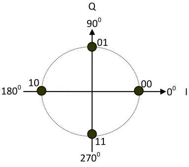
2.4.7 Quadrature Phase Shift Keying (QPSK)
14
[image:25.612.255.446.123.291.2]for gray coding and each adjacent symbol only differs in one bit and has constant amplitude.
Figure 2.6: Constellation Diagram for QPSK
2.4.8 QAM Modulator
Figure 2.7 shows the QAM modulator block diagram. The binary input is the first to be transmitted is split into two equal parts. This process generates two independent signals which are d1 and d2 are ready to be transmitted. One of the channels is multiplied by the cosine which is generated by the carrier oscillator, while the other channel is multiplied by a sine that is 900 phase shift from the carrier oscillator. These two signals are sum up and become the QAM signal.
2700 900
Q
00
I 1800 10
01
00
2-bit Serial-to-parallel converter 2
Binary input d(t) R bps d1(t) R/2 bps d1(t) R/2 bps Carrier oscillator Phase shift t fc 2 cos t fc 2 sin QAM Signal out s(t)
Figure 2.7: QAM Modulator
2.5 PAPR Reduction Techniques
One of the major disadvantages of OFDM systems is that the OFDM signal has high Peak to Average Power Ratio (PAPR), and to deal with this problem many typical techniques have been proposed. Each one is different from others in complexity and performance, and can be divided into three major categories:
2.5.1 Signal distortion techniques .Signal Clipping
. Peak windowing . Peak cancellation
16
2.5.1.1 Signal Clipping
Clipping is the simplest technique that is used to reduce PAPR in OFDM system. The basic idea of this technique is to clip the parts of the signals that have high peak outside of the allowed region. The following equation shows the amplitude clipping [9].
(2.1)
Where A is a positive real number and it presents the clipping level.
Figure 2.8: Amplitude of transmitted OFDM symbol
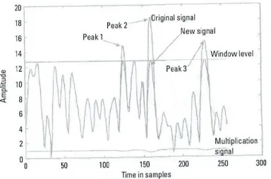
2.5.1.2 Peak windowing
18
Figure 2.9: Windowing an OFDM time signal
2.5.1.3 Peak Cancellation
Figure 2.10: A Block diagram of PAPR reduction by Peak Cancelation
Figure 2.11: OFDM symbol envelop (a) signal envelope after peak cancellation (b)
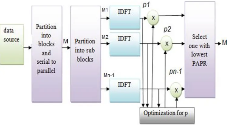
2.5.1.4 Partial Transmit Sequences (PTS)
Partial transmit sequences (PTS) is one of the most important methods that is used to reduce PAPR in the OFDM system. And it can be presented in two main steps. First, by dividing the original OFDM signal into a number of sub-blocks.
Serial to
parallel IFFT
add CP and window
RF transmitter Digital to
analog converter Peak
cancellation Parallel
[image:30.612.164.527.294.530.2]20
Secondly, adding the phase rotated sub-blocks to develop a number of candidate signals to pick the one with smallest PAPR for transmission. There is another way that it can also be used to express PTS method by multiplying the original OFDM signal with a number of phase sequences [11].
Let us assume that M = {Mk}, where (k = 0,… ,N -1) , is the frequency
domain (FD) data of an OFDM signal xn = inverse discrete Fourier transform
(IDFT) { Mk} (n = 0,…, N -1) , where N is the number of subcarriers. It can be
reduced the PAPR of signal m = {mn} by using PTS method in the following steps
Make F is the frequency domain (FD) data sequences, MԐ ( Ԑ = 1,…,F ), by multiplying the phase sequences PԐ = { }(k = 0,1, …, N-1) with X elements , it can get the following result,
MԐ= [ M0, M1,…, MN-1 ] , = 1,…,F (2.2)
Where = exp (j ), is uniformly distributed in (0, 2π ). Get M candidates time domain (TD) via IDFTs
Figure 2.12: A block diagram of the PTS technique.
2.5.1.5 Selected Mapping
22
2.6 Previous studies
2.6.1 lakhendrakuma rgupta, brajendra kumar,ashishmishra,asutoshkumar “PAPR Reduction using modified selective mapping technique” student of ec, kanpur institute of technology volume 3, may- 2013.
This paper Studied Multicarrier modulation is an attractive technique for fourth generation wireless communication. Orthogonal Frequency Division Multiplexing (OFDM) is multi-carrier transmission scheme. Its high Peak to Average Power Ratio (PAPR) of the transmitted signal is a major drawback . The paper also compared PAPR QPSK-OFDM with and without SLM. A modified selective mapping technique is proposed in this paper to improve the performance of the OFDM system with respective PAPR. Results of simulation of modified SLM technique show that the PAPR reduction of OFDM system, which further results in high performance of wireless communication. With the rising demand for efficient frequency spectrum utilization, OFDM proves in valuable to next generation communication systems.
2.6.2 Seung hee han, student member, and jae hong lee, senior member “Modified Selected Mapping Technique for PAPR reduction of coded OFDM signal” 11, November- 2013.
cumulative distribution function (CCDF) of the PAPR of the modified SLM technique is derived and compared with the simulation results.
2.6.3 Hybrid scheme Polytechnic “PAPR reduction of OFDM signals using selective mapping and clipping” University, Faculty of Electronics and Telecommunications, Communication Department, Bucharest, Romania, August 27 ,31- 2012.
24
CHAPTER3
METHODOLOGY
3.1 Introduction
The goal of this project is to evaluate the performance of OFDM system. This discusses the definition of PAPR and the high PAPR issues. And then represent
existing popular PAPR reduction schemes such as, Clipping, Interleaving, and
Coding and discusses selected mapping (SLM) technique which is a well known
technique to reduce the peak-to-average power ratio (PAPR).
3.2 Simulation Methodology
References
1. Jolania, S., & Toshniwal, S. (2014). Performance Improvement of OFDM System Using Iterative Signal Clipping With Various Window Techniques for PAPR Reduction. arXiv preprint arXiv:1402.1759.
2. Manikandam, A., & Sandhiya, M. (2013). Reduction of Inter Carrier Interference using Extended Kalman Filter in OFDM Systems for Different Channel Models. International Journal of Science and Research (IJSR), 2(7), 47-51.
3. Mishra, A. K., & Pandey, R. (1970). A Review on Modelling and Performance of QAM-OFDM System with AWGN Channel.
4. Wang, Z., & Giannakis, G. B. (2003). Complex-field coding for OFDM over fading wireless channels. Information Theory, IEEE Transactions on, 49(3), 707-720.
55
6. Armstrong, J. (2009). OFDM for optical communications. Journal of light wave technology, 27(3), 189-204.
7. 8. 9. 10.
patel, j., tomar, e. s. s., & tiwari, a. c. papr threshold in ofdm signals using oicf with awgn channel.
Goldsmith, A. (2005). Wireless communications. Cambridge university press.
Jiang, T., & Wu, Y. (2008). An overview: peak-to-average power ratio reduction techniques for OFDM signals. IEEE Transactions on broadcasting, 54(2), 257
Zolghadrasli, A., & Ghamat, M. H. (2008). An Overview of PAPR Reduction Techniques for Multicarrier Transmission and Propose of New Techniques for PAPR Reduction. Iranian Journal of Electrical and Computer Engineering, 7(2), 115-
11. Wu, P., Lu, G., & Carlemalm-Logothetis, C. (2006). Partial transmit sequence method for reduction of PAPR in real-valued OFDM systems. In NEWCOM-ACoRN Joint Workshop, Vienna, Austria, September 20-22, 2006.
12. Goldsmith, A. (2005). Wireless communications. Cambridge university press.
14. ARUNA, S., & MALLIKA, Y. Reducing Peak to Average Power Ratio of OFDM by Using Selected Mapping.