QUANTITATIVE MIXING ANALYSIS OF LAMINAR FLOW IN STATIC MIXER WITH SPACE FILLING CIRCLE GRID PERFORATED PLATE
MOHD ZAMADI BIN MAT LODDIN
A project report submitted in partial
fulfillment of the requirement for the award of the Degree of Master of Mechanical Engineering
Faculty of Mechanical and Manufacturing Engineering Universiti Tun Hussein Onn Malaysia
ABSTRACT
ABSTRAK
CONTENTS
TITLE i
DECLARATION ii
ACKNOWLEDGEMENT iii
ABSTRACT iv
ABSTRAK v
CONTENTS vi
LIST OF TABLES x
LIST OF FIGURES xiii
LIST OF APPENDIX xvi
LIST OF SYMBOLS AND ABBREVIATIONS xvii
CHAPTER 1 INTRODUCTION 1
1.1 Fluid Mixing Process 1
1.1.1 Basics of the Mixing Technology 3 1.1.2 Characterization of Particle Mixtures 4
1.2 Research Background 8
1.3 Problem Statement 8
1.4 Research Objective 10
1.5 Scopes of Study 10
CHAPTER 2 LITERATURE REVIEW 11
2.1 Introduction 11
2.2 Characteristics and Concept of Static Mixer 11
2.2.1 Fractal Pattern 11
2.2.3 Pressure Drop 22 2.2.4 Coefficient of variance (COV) 23 2.3 Computational Fluid Dynamic 24
2.3.1 ANSYS Software 24
2.3.2 ANSYS Process 25
2.3.3 Simulation in ANSYS Software 26 2.3.4 Analysis of Fluid Flow 27
2.4 Previous research 28
2.4.1 Two-phase laminar flow simulation 28
CHAPTER 3 METHODOLOGY 31
3.1 Introduction 31
3.2 Flow Chart of Research 32
3.3 Modelling of the Cylindrical Pipeline and
Kenics Static Mixer 34
3.3.1 Computational Fluid Dynamics (CFD)
simulation of the Kenics static mixer 35 3.4 Modelling of the Cylindrical Pipeline and Circle
Grid Perforated Plate with 50% porosity 36 3.4.1 Computational Fluid Dynamics (CFD)
simulation of the Circle Grid Perforated
Plate with 50% porosity 38 3.5 Modelling of the Cylindrical Pipeline and
Circle Grid Perforated Plate with 75% porosity 38 3.5.1 Computational Fluid Dynamics (CFD)
simulation of the Circle Grid Perforated
Plate with 75% porosity 39
CHAPTER 4 RESULTS AND DISCUSSION 42
4.1 Introduction 42
4.2 Post processing (Simulation Result) 42 4.3 Laminar Flow Simulations in Kenics
Static Mixer by ANSYS CFX Software
for Reynolds Number 400 43
4.4 Analysis of laminar flow simulations between ANSYS CFX software and Fluent 5.4.8 in previous research study (Pianko-Oprych, 2002)
for Reynolds Number 400 45
4.5 Laminar Flow Simulations in Kenics Static Mixer by ANSYS CFX Software for
Reynolds Number 200 47
4.6 Laminar Flow Simulations in Kenics Static Mixer by ANSYS CFX Software for
Reynolds Number 100 48
4.7 Laminar Flow Simulations in Circle Grid Perforated Plate of 50% porosity by ANSYS
CFX Software for Reynolds Number 100 50 4.8 Laminar Flow Simulations in Circle Grid
Perforated Plate of 50% porosity by ANSYS
CFX Software for Reynolds Number 200 52 4.9 Laminar Flow Simulations in Circle Grid
Perforated Plate of 50% porosity by ANSYS
CFX Software for Reynolds Number 400 54 4.10 Laminar Flow Simulations in Circle Grid
Perforated Plate of 75% porosity by ANSYS
CFX Software for Reynolds Number 100 56
CFX Software for Reynolds Number 200 58 4.12 Laminar Flow Simulations in Circle Grid
Perforated Plate of 75% porosity by ANSYS
CFX Software for Reynolds Number 400 60
4.13 Comparison between the Effectiveness of
Static Mixer at Certain Condition 61
CHAPTER 5 CONCLUSION AND RECOMMENDATION 64
5.1 Conclusion 64
5.2 Recommendation 65
REFERENCES 66
APPENDICES 69
LIST OF TABLES
TABLE TITLE PAGE
1.1 Type of mixing process 6
2.1 Commercially available static mixers 19 2.2 Industrial applications of commercial static
Mixers 19
2.3 Applications of static mixers in the process
Industries 20
2.4 The continuous (CMC) and dispersed (silicon oil)
phase velocities, oil drop size, and Weber 29 3.1 Mesh Sizing and Parameters of Kenics Static
Mixer, Reynolds Number 400 40
4.1 Homogeneity level of the local volume fraction for the dispersed phase, Silicon oil 50, in Kenics
Static Mixer, Re = 400 44
4.2 Pressure drop of the continuous (CMC) and dispersed (Silicon oil 50) phase, in Kenics Static
Mixer, Re = 400 44
4.3 Simulation result of homogeneity level between ANSYS CFX software and Fluent 5.4.8 in Kenics
Static Mixer for Reynolds Number 400 45
4.4 Simulation result of pressure drop between ANSYS CFX software and Fluent 5.4.8 in Kenics
Static Mixer 46
Mixer, Re = 200 47 4.6 Pressure drop of the continuous (CMC) and dispersed
(Silicon oil 50) phase, in Kenics Static Mixer, Re = 200 48 4.7 Homogeneity level of the local volume fraction for the
dispersed phase, Silicon oil 50, in Kenics Static Mixer,
Re = 100 49
4.8 Pressure drop of the continuous (CMC) and dispersed
(Silicon oil 50) phase, in Kenics Static Mixer, Re = 100 49 4.9 Homogeneity level of the local volume fraction for the
dispersed phase, Silicon oil 50, Grid Perforated Plate
(50% Porosity) Static Mixer, Re = 100 50 4.10 Pressure drop of the continuous (CMC) and dispersed
(Silicon oil 50) phase, in Grid Perforated Plate
(50% Porosity) Static Mixer, Re = 100 51 4.11 Homogeneity level of the local volume fraction for
the dispersed phase, Silicon oil 50, Grid Perforated
Plate (50% Porosity) Static Mixer, Re = 200 52 4.12 Pressure drop of the continuous (CMC) and dispersed
(Silicon oil 50) phase, in Grid Perforated Plate
(50% Porosity) Static Mixer, Re = 200 53 4.13 Homogeneity level of the local volume fraction for the
dispersed phase, Silicon oil 50, Grid Perforated Plate
(50% Porosity) Static Mixer, Re = 400 54 4.14 Pressure drop of the continuous (CMC) and dispersed
(Silicon oil 50) phase, in Grid Perforated Plate
(50% Porosity) Static Mixer, Re = 400 55 4.15 Homogeneity level of the local volume fraction for the
dispersed phase, Silicon oil 50, Grid Perforated Plate
(Silicon oil 50) phase, in Grid Perforated Plate
(75% Porosity) Static Mixer, Re = 100 57 4.17 Homogeneity level of the local volume fraction for the
dispersed phase, Silicon oil 50, Grid Perforated Plate
(75% Porosity) Static Mixer, Re = 200 58 4.18 Pressure drop of the continuous (CMC) and dispersed
(Silicon oil 50) phase, in Grid Perforated Plate
(75% Porosity) Static Mixer, Re = 200 59 4.19 Homogeneity level of the local volume fraction for
the dispersed phase, Silicon oil 50, Grid Perforated Plate (75% Porosity) Static Mixer, Re = 400 60 4.20 Pressure drop of the continuous (CMC) and dispersed
(Silicon oil 50) phase, in Grid Perforated Plate
LIST OF FIGURES
FIGURE TITLE PAGE
1.1 Types of mixture in mixing states 5
1.2 Horizontal drum mixer 7
2.1 Variant of Sierpinski Carpet Fractal Concept
and Circle Grid Fractal Pattern 13
2.2 Description of circle grids space filling flow
conditioner plate 14
2.3 Statiflo Channel and pipe mixers 18
2.4 Elements of different commercial static mixers 18 2.5 Sequence in finite volume software application 25
2.6 The Kenics insert 29
2.7 Pressure drop in the Kenics static mixer versus
Reynolds number 29
2.8 Distribution of the local volume fraction for the dispersed phase, silicon oil 50 in refined CMC,
the Kenics static mixer 30
3.1 Research Flow Chart 33
3.2 Drafting of Kenics Mixing Tube 34
3.3 Drafting of 1 insert of Kenics Static Mixer 35 3.4 Boundary Condition of Kenics Static Mixer
Geometry 36
3.5 Drafting of Circle Grid Perforated Plate with
50% Porosity 37
3.6 Drafting of Circle Grid Perforated Plate with
4.1 Distribution of the local volume fraction for
the dispersed phase, Silicon oil 50 in refined CMC,
the Kenics Static Mixer, Re = 400 43 4.2 Distribution of the local volume fraction for the
dispersed phase, silicon oil 50 in refined CMC, the
Kenics static mixer, Re = 400 45
4.3 Distribution of the local volume fraction for the dispersed phase, Silicon oil 50 in refined CMC,
the Kenics Static Mixer, Re = 200 47 4.4 Distribution of the local volume fraction for the
dispersed phase, Silicon oil 50 in refined CMC,
the Kenics Static Mixer, Re = 100 48 4.5 Distribution of the local volume fraction for the
dispersed phase, Silicon oil 50 in refined CMC, the Circle Grid Perforated Plate (50% Porosity)
Static Mixer, Re = 100 50
4.6 Distribution of the local volume fraction for the dispersed phase, Silicon oil 50 in refined CMC, the Circle Grid Perforated Plate (50% Porosity)
Static Mixer, Re = 200 52
4.7 Distribution of the local volume fraction for the dispersed phase, Silicon oil 50 in refined CMC, the Circle Grid Perforated Plate (50% Porosity)
Static Mixer, Re = 400 54
4.8 Distribution of the local volume fraction for the dispersed phase, Silicon oil 50 in refined CMC, the Circle Grid Perforated Plate (75% Porosity)
Static Mixer, Re = 100 56
the Circle Grid Perforated Plate (75% Porosity)
Static Mixer, Re = 200 58
4.10 Distribution of the local volume fraction for the dispersed phase, Silicon oil 50 in refined CMC, the Circle Grid Perforated Plate (75% Porosity)
Static Mixer, Re = 400 60
4.11 Graph of Coefficient of Variance versus
LIST OF APPENDICES
APPENDIX TITLE PAGE
A Drafting of Mixing Pipeline of Circle
Grid Perforated Plate with 50% Porosity 70 B Overall result of Silicon oil 50 volume
fraction in Kenics Static Mixer 71 C Overall result of Silicon oil 50 volume
fraction in Circle Grid Perforated Plate
(50% Porosity) Static Mixer 73 D Overall result of Silicon oil 50 volume
fraction in Circle Grid Perforated Plate
(75% Porosity) Static Mixer 75
E Gantt chart of Master’s Project 1 77
F Gantt chart of Master’s Project 2 78
LIST OF SYMBOLS AND ABBREVIATIONS
Dh - Hydraulic Diameter
F - Fanning Factor L - Length of the Tube N - Number of data points ∆p - Pressure Drop
v - Velocity of fluid Re - Reynolds Number ρ - Density of Fluid
xi - Each of the Data Values x - The mean of the xi σ - Standard Deviation μ - Dynamic Viscosity COV - Coefficient of Variation
CHAPTER 1
INTRODUCTION
1.1 Fluid Mixing Process
Basically, the applications of the static mixers is widely applied in many industries such as petrochemical and refining, chemical and agricultural chemicals production, minerals processing, grain processing, food processing, pharmaceuticals and cosmetics, polymers, plastics, textiles, paints, resins and adhesives, pulp and paper, water and waste water treatment.
The static mixers are used in continuous processes as an alternative way to conventional agitation since similar and sometimes better performance can be achieved at lower cost. The static mixers have not involved in moving parts and at the same time it will have lower energy consumptions, smaller space requirements, low equipment cost and reduced maintenance requirements compared with mechanically stirred mixers. They offer a more controlled and scale able rate of dilution in fed batch systems and can provide homogenization of feed streams with a minimum residence time. They also provide good mixing at low shear rates where locally high shear rates in a mechanical agitator may damage sensitive materials. Static mixers also come with self cleaning features. Interchangeable and disposable static mixers are also available. (Etchells III A.W., 2004)
1.1.1 Basics of the Mixing Technology
1.1.1.1 Homogenising
Homogenising in the mixing technology is mixing certain inter-soluble liquids up to a certain homogenizing degree (mixing quality) or the up-keep of the homogeneity for a certain reaction. The liquids to be mixed may be differ for instance in concentration, colour or temperature. The time period needed for mixing is the homogenizing time. (Hintz, 2008)
1.1.1.2 Suspending
Suspension is the even distribution of solid particles in a liquid (homogeneous mass). The mixer avoids sedimentation of the solid particles in the liquid. A mixture of solid particles and liquids subjects the mixing equipment to excessive wear, which is proportional to the third power of the circumferential speed (tip speed) of the mixing tool. It is therefore recommend that the speed be kept to the barest minimum. This is often also advantageous to the product. (Hintz, 2008)
1.1.1.3 Dispersing
Dispersing is the mixing process of two liquids which normally are insoluble. The drops (≥ 1µm) of the dispersing phase are spread over the continuous phase. Dispersions are unstable and demix when the power is too low or lacking totally. The actual task of dispersing is the enlargement of the phase border line so that for instance the process of chemical reaction is faster. (Hintz, 2008)
1.1.1.4 Gasification
foremost the uncontrolled gasification, the gas is pumped through a ring shower into the vessel, the stirring tool crushes the gas flow into small bubbles and divides them in the liquid. (Hintz, 2008)
1.1.1.5 Heat Exchange
A controlled heat transfer is very essential in many processes. Due to an unfavourable ration of heat transfer areas to the vessel volume only very little heat per time unit can be transferred. Improved heat exchange can be obtained through a suitable mixing tool. Its function is to produce a flow along the heat transfer areas (vessel jackets) such as to improve the heat transfer coefficient and thereby the heat transit coefficient. (Hintz, 2008)
1.1.2 Characterization of Particle Mixtures
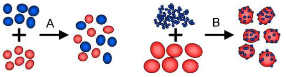
Julio De Paula et al. (2002) stated that, based on chemistry study a mixture is not combined chemically and the material just mix by two or more different substances. A mixture refers to the physical combination of two or more substances on which the identities are retained and are mixed in the form of suspensions, solutions and colloids. Mixtures are the chemical substances that are mixed by mechanical blending or mixing in order to produce a specific product. The chemical substances have fully transformed to the specific product without chemical bonding or other chemical change. So, each of the chemical substances retains its own chemical properties.
1.1.2.1 Characterization of Mixing States of a Granular or Particular Material
Figure 1.1: Types of mixture in mixing states: (A) Random mixture; (B) Interactive mixture. (Bridgewater, 1976)
1.1.2.2 Process Principles for Input of Mechanical Energy into Particulate
Systems.
[image:21.595.102.532.568.744.2]Berk, (2009) stated that the prime objective of mixing is to have homogeneity (uniform distribution) in the product. The homogenization of the mixture usually is done by the reduction of particle size achieved by the action of shearing forces. The effective energy input by unit mass or unit volume fluid will affect the quality of mixing. The important power correlations in the field of mixing are the power number, Reynolds number and Froude number. These correlations will help to know deeply on the forces taking place in each case of mixing, relating the dimensions, type and operating conditions. The Reynolds number is a very important parameter because it helps to understand the flow regime. The Froude number contains the gravitational forces, the Reynolds number describes the inertial and viscous forces and the power number relates the power (torque) with the diameter of the impeller, speed shaft and density of the liquid. Table 1.1 shows the types of mechanically mixing process that usually applied in industries which require mechanical energy in order to mix of the substances. Each of the mixing process can be applied for certain substances or materials depend on the homogeneity level that is required to produce specific product in certain applications.
Table 1.1: Type of mixing process (Hintz, 2008)
Process principle Schematic sketch Example
Rotating process chambers or vessels
Drum mixer, drum mill, drum dryer
Agitated systems Mechanical silo
Table 1.1(continued): Type of mixing process (Hintz, 2008)
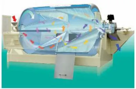
Figure 1.2: Horizontal drum mixer (Agratechniek, 2009)
Figure 1.2 shows one type of the mixer which is horizontal drum mixer that consist inner blades. The horizontal drum mixer operates as the material flows through the inlet opening into the mixing chamber. The mixing process will be started when the entire product is loaded and slips over the inner blades. This type of mixer has no stationary segments which not deal with risk of separation. All components are continuously and randomly picked up and moved through the drum. After the mixing time the valve opens and mixing chamber will be discharged automatically. (Agratechniek, 2009)
Flow of fluids through granular beds
Pneumatic silo discharging, pneumatic
homogenization, fluidized beds
Vibrations Vibration systems for
[image:22.595.108.531.156.314.2] [image:22.595.201.435.349.502.2]1.2 Research Background
Nowadays, mixing operations are essential in the process industries. They include the classical mixing of miscible fluids in single phase flow as well as heat transfer enhancement, dispersion of an immiscible organic phase as drops in a continuous aqueous phase, three-phase contacting and mixing of solids. Static mixer have been applied to all this applications including liquid-liquid systems (extraction), gas-liquid systems (absorption), solid-liquid systems (pulp slurries) and solid-solid systems (solid blending). Static mixers are now commonly used in the chemical and petrochemical industries to perform continuous operations.
The effectiveness of static mixers for the miscible fluid or to enhance heat transfer is due to their ability to perform radial mixing and to bring fluid elements into close proximity so that diffusion or conduction becomes rapid. In laminar flows, static mixers divide and redistribute streamlines in a sequential method by using only the energy of the flowing fluid. In order to design optimal mixer geometries, appropriate tools and methods are needed to characterize the flow conditions and their influence on the mixing process. In addition, concentration distributions were determined as an essential measure of homogeneity level. A widely used measure for presenting the uniformity of concentration at a cross section of static mixer is the coefficient of variation (COV). The COV is defined as the standard deviation of concentration over the mean concentration for a given set of N data points. The data used to calculate the COV are taken from volume fraction at the specific cross section planes of interest in this study.
1.3 Problem Statement
robust and maintenance free, tanks and agitators are not needed because of inline production process and easy to install in piping system also no special knowledge needed.
In industry, there are many types of static mixer have been designed and it is used widely in industry. However, there are many static mixers that have been proposed in industry having complex and complicated in design. The type of static mixer that usually used in industry is Kenics, SMX, SMI, SMV, KVM and Compax Static Mixer. Each of static mixers has their own arrangement and shape of mixer that is designed in order to get better efficiency to mix the fluid homogeneously. At the same time, each of the design requires high cost of manufacturing and need to spend a lot of time in manufacturing and installation.
1.4 Research Objective
This research study embarks on the following objectives:
1) To propose a new approach of fractal concept (circle grid space filling fractal) for internal rapid mixing by determining the coefficient of variation (COV).
2) To assess a capability of fractal pattern in mixing process.
3) To make a recomendation for new concept of static mixer in pipe flow by using a fractal concept based on space filling circle grids fractal.
1.5 Scopes of Study
To conduct this research study, several scopes have been outlined:
1. The simulation is done primarily in cylindrical pipe with insertions of perforated plate to make it functioning as static mixer.
2. The perforated plate with circle grid pattern which porosity of 50% and 75% will be applied.
3. Three levels of laminar flow will be chosen to result in Reynolds numbers (Re) equal to 100, 200 and 400 respectively.
4. This study will be implemented by fully numerical simulations.
CHAPTER 2
LITERATURE REVIEW
2.1 Introduction
This chapter reviews on the literature such as journals, books, website and articles that related to the mixing analysis of laminar flow in static mixer with space filling circle grid perforated plate. This literature review will cover on:
2.1 Reviews on concept and mixer working principle of static mixer. 2.2 Reviews on Computational Fluid Dynamic (ANSYS Software). 2.3 Reviews on previous research which related to the case study.
2.2 Characteristics and Concept of Static Mixer
2.2.1 Fractal Pattern
pattern from near and far position. It has exactly the same pattern whether it use a different scales. It is the idea of pattern which having detailed pattern repeating itself and infinite. The term "fractal" was first used by mathematician Benoît Mandelbrot in 1975. The fractal have been taken based on the Latin frāctus meaning "broken" or "fractured", and used it to extend the concept of theoretical fractional dimensions to geometric patterns in nature. (Mandelbrot, 2004)
Generally, the way on how to define fractal concept have some disagreement amongst authorities. But, the majority people who have studied about fractal concepts agree that theoretical fractals are infinitely self-similar, iterated, and having fractal dimensions with detailed mathematical constructs. The fractal concept is not just about geometric pattern, but it also can describe processes in time. Based on the fractal concept, it is extensively studied about various degrees of self-similarity such as structures, image, technology, art, law and nature. The fractal pattern can be modelled which considering of physical time and space.
2.2.1.1 Koch Curve
The curve of Von Koch is one of the applications of fractal concept which is generated by a simple geometric procedure. This simple geometry can be iterated an infinite number of times by dividing a straight line segment into three equal parts and substituting the intermediate part with two segments of the same length.(Riddle, 2013)
2.2.1.2 Koch Snowflake
According to Poitevint (2003), the Koch snowflake usually called as the Koch star and Koch Islandis a mathematical curve and one of the earliest fractal curves to have been described. It is based on the Koch curve, which appeared in a 1904 paper titled "On a continuous curve without tangents, constructible from elementary geometry" by the Swedish mathematician Helge von Koch.
Other than Koch snowflake, the fractal concept had been derived to develop more pattern concepts. The sierpinski carpet is a plane fractal first described by Wacław Sierpiński in 1916. The sierpinski carpet begin with a square. The square is cut into 9 congruent subsquares in a 3-by-3 grid, and the central subsquare is removed. The same procedure was carried out to present the pattern same as Figure 2.1(a) (Wikipedia, 2013). According to the sierpinski carpet concept, circle grid fractal pattern had been developed by using turtle graphic as shown in Figure 2.1 (b). (Programming, algorithms, coding in practice, 2012
[image:28.595.154.488.479.586.2]Figure 2.1(b): Circle Grid Fractal Pattern (Programming, algorithms, coding in practice, 2012)
2.2.1.3 Mathematical Formulation for Geometry of the Circle Grids Space
Filling Plate
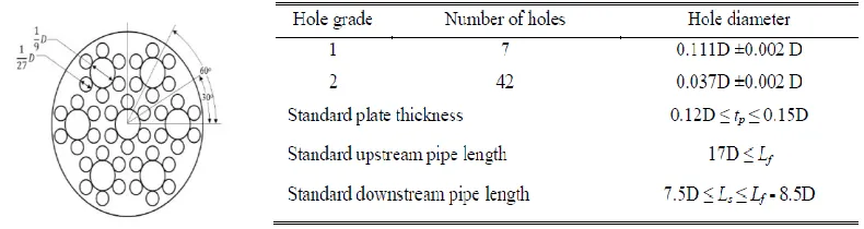
[image:29.595.177.461.122.213.2]According to Bukhari Manshoor (2012), circle grids space filling plate has two grades of holes which different dimension, as described in Figure 2.2. The smaller holes are concentrated near the plate edge because the major concentration of eddies and swirl is near the wall. On the other hand, this radial reduction of holes diameter assists in stabilizing the velocity distribution. The geometry of holes is expressed in terms of plate diameter. The geometry of circle grids space filling plate basically come from the idea of fractal pattern with specific ratio has been defined. (Bukhari Manshoor, 2012)
[image:29.595.124.519.573.678.2]According to G. Coppola (2009),blockage ratiois defined as ratio of the area blocked by the grid to the whole area of the channel/tunnel square or circle section before it become turbulent or laminar flow. Blockage ratio can be opposite meaning with porosity which porosity means the holes area of the channel/tunnel square or circle section. It can be easily described by percentage value of blockage ratio or porosity.
2.2.2 Static mixer and working principle
According to Charles Ross, in the process industries, static mixers or motionless mixers are the standard equipment that is usually used for fluid mixing process. The application of static mixers is inline in a once-through process or as supplement or replace a conventional agitator. Generally, the static mixers are suitable used in continuous processes where as alternative to conventional agitation. At lower cost, it might be similar or sometimes give better performance than conventional agitation. Furthermore, static mixers have no moving parts that will affect to the lower energy consumptions and reduced maintenance requirements. They are available in most materials of construction. (Charles Ross)
In industries, static mixers have been applied in wide range of process operations such as laminar flow heat exchange, dispersion and emulsion formation. Basically, static mixers has been tested and trusted in many different industries for combining liquids, gases and powders. The mixing process can be done by continuous splitting, extension and transportation of the components. Differences in concentration, temperature and velocity are equalized over the flow cross-section. They are manufactured in a wide range of materials, including carbon steel, stainless steel, exotic alloys, Glass-reinforced plastic (GRP), Unplasticized Polyvinyl chloride(uPVC),Chlorinated polyvinyl chloride (cPVC) and Polytetrafluoroethylene (PTFE).
elements for the industries application. Static mixers deliver a high level of mixing efficiency, therefore the consumption of dosed chemicals and formation of by-products can be dramatically reduced. It has highly efficient mixing with low energy consumption and at the same time will replace the equipments such as tanks, agitators, moving parts and direct motive power to the simpler mixing elements.
The energy required for mixing is efficiently extracted as pressure drop from the fluid flow through the elements. Mixers are invariably installed in existing systems without reducing the capacity of existing pumps. The installation is very easy and no special skills are required other than normal engineering skills. Static Mixers are available in all standard pipe sizes and in the case of open channel designs are available in any size with no upper limit. Each Static Mixer is carefully designed to meet the specific requirements of each application.(Thottam)
2.2.2.1 Principles of operation
According to Lenntech (2012), there are three simple cases of mixing operation which depends on the type of flow and liquids. The first case is two miscible liquids in laminar flow which the main mechanism in a static mixer is flow division. The elements split the fluids entering in two streams and then rotate them through 180 degrees. The elements are arranged in a series of alternating left and right hand 180 twists. The elements are in series in the mixer. As the number of streams or layers increases, the layer thickness decreases. Normally, 12 to 24 elements are required to provide a complete mix.
The second case is two miscible liquids in a turbulent flow which the main mechanism is radial mixing. The fluids are continuously moving from the pipe centre to the pipe walls and the fluid change direction with each succeeding element. Normally, a fully homogeneous mix in a turbulent flow requires about 1.5 to 4 elements.
disperser length necessary depends on the required contact time. For mass transfer processes in which equilibrium is quickly established, a length of 5 diameters is generally sufficient. (Lenntech, 2012)
2.2.2.2 Types and Applications
According to Lenntech (2012), static mixers provide the highest standard of mixing efficiency, reliability and economy for thousand of process plants worldwide. The static mixers can be categories in group such as channel mixers, pipe mixers and gas dispersion systems.
i) Channel mixers:
It is installed in new treatment works in existing installations. They rapidly achieve a high degree of mix with extremely low head loss on very short lengths. Channel mixers cover a wide range of flow rates and are ideal for efficient chemical dosing. They allow chemical savings with consequently economical and environmental savings. Figure 2.3(a) shows the one of the channel mixer.
ii) Pipe Mixers:
The range of materials of mixer can be in stainless steel, PVC, Polypropylene (PP) and carbon steel. It can be fixable or removable. It is available with heating and cooling jackets, injectors, sample points and instrumentation bosses. It is suitable for all industries. It has wide range of diameters which is from 10 to 300 cm. Figure 2.3(b) shows the one of the channel mixer.
iii) Gas Dispersion systems:
(a) (b)
[image:33.595.171.466.276.574.2]Figure 2.3: (a) Statiflo Channel and (b) pipe mixers (Lenntech, 2012)
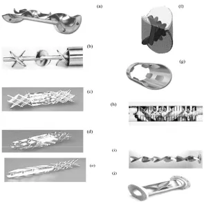
Figure 2.4: Elements of different commercial static mixers:
(a) Kenics (Chemineer Inc.); (b) low pressure drop (Ross Engineering Inc.); (c) SMV (Koch-Glitsch Inc.); (d) SMX (Koch-Glitsch Inc.); (e) SMXL (Koch-Glitsch Inc.);
(f) Interfacial Surface Genera;(g) HEV (Chemineer Inc.);(h) Inliner series 50 (Lightnin Inc.); (i) Inliner series 45 (Lightnin Inc.); (j) Custody transfer mixer
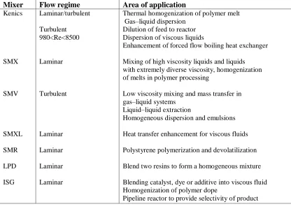
According to Thakur et al (2003), Figure 2.4 shows the several types of static mixer that are readily available in market for industries application. Table 2.1, 2.2 and 2.3 show the companies that have designed each of the static mixers, the capability of static mixer in specific area of applications.
Table 2.1: Commercially available static mixers (Thakur et al. ,2003)
Company Mixers
Chemineer-Kenics
Koch-Sulzer
Charles Ross & Son
Wymbs Engineering
Lightnin EMI Komax
Brann and Lubbe Toray
Prematechnik
Kenics mixer (KM), HEV (high efficiency vortex mixer) Sulzer mixer SMF, SMN, SMR, SMRX, SMV, SMX, SMXL ISG (interfacial surface generator), LPD (low pressure drop), LLPD HV (high viscosity), LV (low viscosity)
Inliner Series 45, Inliner Series 50 Cleveland
Komax N-form
Hi-Toray Mixer
PMR (pulsating mixer reactor)
Table 2.2: Industrial applications of commercial static mixers (Thakur et al. ,2003)
Mixer Flow regime Area of application
Kenics SMX SMV SMXL SMR LPD ISG Laminar/turbulent Turbulent 980<Re<8500 Laminar Turbulent Laminar Laminar Laminar Laminar
Thermal homogenization of polymer melt Gas–liquid dispersion
Dilution of feed to reactor Dispersion of viscous liquids
Enhancement of forced flow boiling heat exchanger
Mixing of high viscosity liquids and liquids with extremely diverse viscosity, homogenization of melts in polymer processing
Low viscosity mixing and mass transfer in gas–liquid systems
Liquid–liquid extraction
Homogeneous dispersion and emulsions
Heat transfer enhancement for viscous fluids
Polystyrene polymerization and devolatilization
Blend two resins to form a homogeneous mixture
Blending catalyst, dye or additive into viscous fluid Homogenization of polymer dope
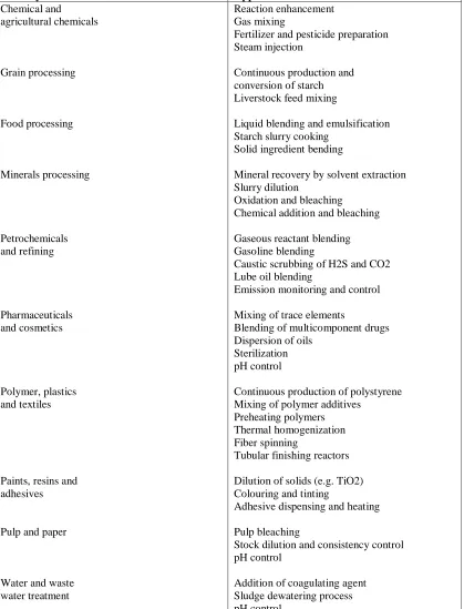
[image:34.595.109.525.479.778.2]Table 2.3: Applications of static mixers in the process industries (Thakur et al. ,2003)
Industry Application
Chemical and agricultural chemicals Grain processing Food processing Minerals processing Petrochemicals and refining Pharmaceuticals and cosmetics Polymer, plastics and textiles
Paints, resins and adhesives
Pulp and paper
Water and waste water treatment
Reaction enhancement Gas mixing
Fertilizer and pesticide preparation Steam injection
Continuous production and conversion of starch Liverstock feed mixing
Liquid blending and emulsification Starch slurry cooking
Solid ingredient bending
Mineral recovery by solvent extraction Slurry dilution
Oxidation and bleaching
Chemical addition and bleaching
Gaseous reactant blending Gasoline blending
Caustic scrubbing of H2S and CO2 Lube oil blending
Emission monitoring and control
Mixing of trace elements
Blending of multicomponent drugs Dispersion of oils
Sterilization pH control
Continuous production of polystyrene Mixing of polymer additives
Preheating polymers Thermal homogenization Fiber spinning
Tubular finishing reactors
Dilution of solids (e.g. TiO2) Colouring and tinting
Adhesive dispensing and heating
Pulp bleaching
Stock dilution and consistency control pH control
2.2.2.1 Kenics Static Mixers
According to Robbins (2013), Kenics Static Mixers have been installed in worldwide since 1965. The installation have set to the standard for in-line mixing and heat transfer performance. Kenics mixer is one of the technology from Chemineer incorporates advanced technology which is responsible for reliable and uninterrupted performance for the long term. The feedback from the installation of Kenics mixer gives maximum operating efficiency and overall cost savings. (Robbins, 2013)
There are several types of static mixer that are available in the market. The KM Static Mixer is designed with helical mixing element directs the flow of material radially toward the pipe walls and back to the centre. In order to increase mixing efficiency, the additional velocity reversal and flow division is required by combining alternating right- and left-hand elements. The HEV and UltraTab Static Mixers are designed with the element geometry which maximizes the conversion of turbulent energy into efficient mixing. The mixing elements are used to produce complete stream uniformity through controlled vortex structures. This type of mixing elements can be easily reproduced and reliably scaled. From previous usage, it shows that Kenics Static Mixers maximize mixing efficiency without the wasted energy and material blockage typically found in more restrictive motionless mixers.
Kenics Static Mixers provide precise blending and dispersion of all flow able materials, without utilizing moving parts. Mixing is achieved by redirecting the flow patterns already present in empty pipe. Kenics Static Mixers are currently being used in numerous processing applications, in order to reduce overall cost and significantly improve efficiency, speed and control. Kenics Static Mixers can be found in a wide range of markets including chemical, refining, polymer, food, pulp and paper, and water and wastewater treatment. These high efficiency mixers also handle other critical processes, such as heating or cooling, residence time control and temperature uniformity. (Robbins, 2013)
2.2.3 Pressure Drop
A greater pressure drop is needed to maintain the same flow rate when mixer elements are inserted in a pipe. There are some procedures in order to get the value of pressure drop in mixing tube. (Sizing The Admixer Static Mixer and Sanitary Static Blender, 1998)
As given by Sylwia Peryt-Stawiarska (2012), the pressure drop, ∆p in a static mixer can be calculated as for an empty tube with help of the Fanning friction factor:
𝑓
2
=
∆𝑝
4𝜌𝑤2
𝐷
𝐿 (2.1)
Where;
f = Fanning factor ∆p = Pressure drop ρ = Density of the fluid D = Hydraulic diameter L = Length of the tube w = Velovity
and for Reynolds number 15 < Re ≤ 1000: 𝑓
2
=
110
𝑅𝑒0.8
+ 0.4
(2.2)Where;
2.2.4 Coefficient of variance (COV)
According to Fan (1990), the homogeneous mixture is a mixture that having mixing element uniformly. There are several factors that influence the homogeneous mixture which are mechanisms of mixing, characteristics of materials to be mixed and characteristics of the mixer. To analyze a mixture, samples are taken from the mixture at random which represent of the state of the mixture. The level of acceptable homogeneity of the mixture depends on each application. It can be specified in terms of variation coefficient, COV. Usually a COV value between 0.01 and 0.05 is a reasonable target of completely homogeneous mixing fluid for most applications. The lower value of COV represents better quality of the homogenous mixture. The standard COV value equal to 0 represents a complete distributive mixing, while COV value more than or equal to 1 represents total segregation.
According to R.V. (2004), the COV is defined as the standard deviation of concentration, 𝛔 over the mean concentration, 𝒙 for a given set of data points.
The standard deviation of concentration is:
σ =
𝑛𝑖=1(𝑥𝑖−𝑥 )2𝑛−1 (2.3)
Where;
σ = Standard deviation
n = The number of data points x = The mean of the xi
xi = Each of the values of the data
An alternative measure of homogeneity is provided by the coefficient of variation:
Where;
COV = Coefficient of variation σ = Standard deviation
x = Mean concentration
2.3 Computational Fluid Dynamic
In this project, ANSYS software is proposed to do simulations of fluid flow in cylindrical pipeline system. Basically, ANSYS software is one of the new Computational Fluid Dynamic (CFD) software that is usually used today. This software provides many features that can be used to study the fluid dynamics, structural mechanics, electromagnetic and systems and multiphysics. In study of fluid dynamics, this software provides the analysis system by using Fluid Flow (CFX), Fluid Flow (Fluent), Fluid Flow(Polyflow), Fluid Flow-Extrussion (Polyflow), Fluid Flow-BlowMolding (Polyflow) and other advanced analysis system. The ANSYS software is used in scope of works starting from drawing of cylindrical pipeline system and static mixer, modeling of the cylindrical pipeline system, simulation and visualization of fluid flow in the cylindrical pipeline system.
2.3.1 ANSYS Software
REFERENCES
AG, A. F. (2008). Air Flow Simulation Helps Optimize Installation and Minimize Operation Costs of a Clean Room.
Agratechniek. (2009). Zaad mixer.
Albright, L. F. (2008). In L. F. Albright, Albright's Chemical Engineering Handbook (p. 682). Boca Raton FL: CRC Press.
Batchelor, G. (2000). Introduction to Fluid Mechanics.
Berk, Z. (2009). Food Process Engineering and Technology. Elsevier Inc.
Bridgewater, J. (1976). Fundamental powder mixing mechanisms. In Powder Technology (pp. 215–236).
Bukhari Manshoor, M. J. (2012). CFD Analysis of Incompressible Turbulent Swirling Flow through Circle Space Filling Plate. World Academy of Science, Engineering and Technology .
Charles Ross, S. C. (n.d.). Solutions to Batch Mixing Issues. Static Mixer Designs and Applications .
Chen, S. (1975). Static Mixing of polymers. Chem Eng Prog.
Etchells III A.W., M. C. (2004). Mixing in pipelines. In Handbook of Industrial Mixing Science and Practice.
Fan, C. a. (1990). Recent Developments in Solids Mixing, Powder Technology. 255– 287 .
Gy., P. (1979). Sampling of Particulate Materials: Theory and Practice. Amsterdam: Elsevier Scientific Pub. Co.
Hersey, A. (1975). Ordered mixing: a new concept in powder mixing practice.
Hintz, D. W. (2008). Particle Technology Powder mixing and blending. Mechanical Process Engineering.
Jiang, X. (2010). Progress in Energy and Combustion Science.
Julio De Paula, P. A. (2002). Atkins' Physical Chemistry. Oxford University Press. Kuntjoro, W. (2005). An Introduction to the Finite Element Method. Singapore: The
MCGraw-Hill Educations(Asia).
Lenntech. (2012). Static Mixers. Retrieved from Water Treatment Solution: http://www.lenntech.fr/francais/melangeurs-statiques.htm
Mandelbrot, B. B. (2004). A fractal set is one for which the fractal dimension strictly exceeds the topological dimension. In Fractals and Chaos (p. 38). Berlin: Springer.
Nagi Elabbasi, X. S. (2012). Modeling of Laminar Flow Static Mixers. COMSOL Conference. Boston, MA: Veryst Engineering.
Pianko-Oprych, Z. J. (2002). Two-Phase Laminar Flow Simulations In A Kenics Static Mixer Standard Eulerian And Lagrangian Approaches. Institution of Chemical Engineers .
Poitevint, M. K. (2003). The Koch Snowflake .
Riddle, L. (2013, April 1). Koch Curve. Retrieved from Classic Iterated Function Systems: http://ecademy.agnesscott.edu/~lriddle/ifs/kcurve/kcurve.htm
Robbins, M. (2013). Product Innovation. In I. Chemineer, Kenics Static Mixing Technology.
R.V., L. D. (2004). Immiscible liquid-liquid systems. In V. A.-O. E.L. Paul, Handbook of Industrial Mixing (pp. 689-753). Hoboken, New Jersey: John Wiley & Sons Inc.
Šibanc, R. (2010). Process Modelling. Use of computational fluid dynamics for analysis of pharmaceutical equipment .
Sizing The Admixer Static Mixer and Sanitary Static Blender. (1998). Advance Mixing Technology .
Sylwia Peryt-Stawiarska, Z. J. (2012). The non-Newtonian fluid flow through the kenics static mixer. 14th European Conference on Mixing, (pp. 365-370). warszawa.
Thakur R. K., V. C. (2003). Static mixers in the process industries. Trans. IChemE. Thottam, M. K. (n.d.). Static Mixers. Retrieved from Faraday Ozone:
www.faradayozone.com
W. Malalasekera, H. K. (2007). An Introduction to Computational Fluid Dynamics. In The Finite Volume Method. Prentice Hall.
Wikipedia. (2013, September 10). Retrieved October 22, 2013, from Sierpinski carpet: http://en.wikipedia.org/wiki/Sierpinski_carpet