iii
DESIGN OF FUZZY CONTROLLER OF INDUCTION MOTOR FOR
ELECTRIC VEHICLE APPLICATION
MUHAMED FAUZIE BIN NOH
A project report submitted in partial fulfilment of the requirement for the award of the
Degree of Master of Electronics Engineering
Faculty of Electrical and Electronics Engineering Universiti Tun Hussein Onn Malaysia
ABSTRACT
viii
ABSTRACT
CONTENTS
TITLE ii
DECLARATION iv
DEDICATION v
ACKNOWLEDGEMENT vi
ABSTRACT vii
CONTENTS ix
LIST OF TABLES xii
LIST OF FIGURES xiii
LIST OF APPENDIXES xv
CHAPTER 1 INTRODUCTION
1.1 Background to the study 1
1.2 Problems Statement 4
1.3 Aim And Objectives Of The Research 5
1.4 Scope of Research 5
1.5 Thesis Outline 5
1.6 Project Planning 6
x
CHAPTER 2 A BRIEF REVIEW OF RESEARCH 7
2.1 Introduction 7
2.2 Induction Motor 8
2.2.1 Construction and Operation 8 2.2.2 Principle of Rotating Magnetic Field 11 2.2.3 Applications of Induction Motor 11
In Electric Vehicle
2.3 Controller 12
2.3.1 Introduction to Fuzzy Logic Controller 13 2.3.2 Application Areas of Fuzzy Logic 14
Controllers
2.3.3 Components of FLC 15
2.3.4 Designing Fuzzy Logic Controller 18
CHAPTER 3 METHODOLOGY 20
3.1 Introduction 20
3.2 Flow Chart 24
3.3 Induction Motor 25
3.3.1 Mathematical model of Induction 25 Motor
3.3.2 Simulation in MATLAB Simulink 26 3.4 Integrating Fuzzy Logic Controller To The 27
System
CHAPTER 4 SIMULATION RESULTS 31
4.1 Introduction 31
CHAPTER 5 CONCLUSIONS AND FUTURE WORK
RECOMMENDATIONS 41
5.1 Conclusions 41
5.2 Suggestion for Future Work 42
REFERENCES 43
xii
LIST OF TABLES
TABLE NUMBER TITLE PAGE
LIST OF FIGURES
FIGURE NUMBER TITLE PAGE
1.1 Basic components in electric vehicle 1
1.2 Project Gantt Chart 6
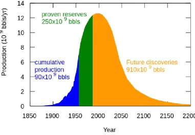
2.1 Hubbert peak oil plot 8
2.2 Stator construction of Induction Motor 9 2.3 Squirrel Cage Rotor constructions 10 2.4 Wound Rotor constructions 10 2.5 Fuzzy Logic Controller Structure 16 2.6 Classes of Membership Functions 18 2.7 Examples of four classes on MF parameter 19 3.1 Electric vehicle Simulink model 21 3.2 FCV Vehicle Dynamics Subsystem 22 3.3 Energy Management Subsystem (EMS) 23 3.4 Flowchart process of the project 24 3.5 Simulink schematic of AC3 25 3.6 Speed controller of the motor 26 3.7 FIS for speed controlling system 28 3.8 Block diagram of PI Fuzzy logic controller 28 3.9 Implemented Fuzzy Simulink model for 29
speed controlling system
xiv
4.2 Performance of controllers based on pedal 33 Position
4.3 RPM results using both controllers 34 4.4 Power calculation using PI and PI Fuzzy 36
respectively
LIST OF APPENDIXES
APPENDIXES TITLE PAGE
CHAPTER 1
INTRODUCTION
1.1 BACKGROUND OF PROJECT
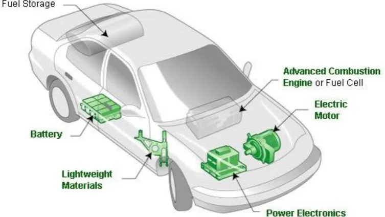
An electric car is an automobile propelled by one or more electric motor powered by batteries or another energy storage device. It has become more popular lately due to growing concern over problems associated with environment pollution caused by fuelled vehicle emission and increasing in oil price worldwide. On the other hand, electric vehicle also benefits in term of cleaner vehicle technologies that helps everyone breathe easier, cut down greenhouse gas emissions and reduce our dependence on oil (wevaonline.net, retrieved on 10 Jun 2013).
be designed is not only for the performance of the vehicle but also for the energy management of the batteries on the vehicle.
Figure 1.1: Basic components in electric vehicle
Conventional controller such as Proportional Integral (PI), Proportional Derivative (PD) or Proportional Integral Derivative (PID) offers very efficient solution, robust and reliable control. The only problem associated with use of conventional PI, PD and PID controllers in speed control of induction motor is the complexity in design arising due to the non-linearity of induction motor dynamics and also due to other components in electric vehicle. The conventional controllers have to linearize the non-linear systems in order to calculate the parameters [3]. The usual method of computation of mathematical model of the induction motor is difficult, due to the non-linearity of motor dynamics. Whenever a variation in system or ambient parameter arises, the system’s behaviour becomes non-pleasing. The conventional controllers designed to provide high performance increase the design complexity along with the cost. To obtain a perfect non-linear model is almost impossible and hence the values of the parameters that are obtained from it are thereby approximate. The conventional control methods possess the following difficulties:
3
2. Expected performance not being met due to the load disturbance [7], motor saturation [7, 6] and thermal deviation [6].
3. Adopting the right coefficients for acceptable results [8].
From the above, it can be concluded that in order to implement conventional controller, it is necessary to have knowledge of the system’s model and all parameter that is needed to be controlled. Due to complex operation condition of electric vehicle, intelligent controller is used to increase efficiency and deal with complex operation modes [9, 10]. There are many artificial intelligence controllers that are widely used and they are:
1. Fuzzy Logic Controller (FLC) 2. Fuzzy-Neural Network (FNN) 3. Neuro Network (NN)
4. Genetic Algorithm (GA)
Fuzzy Logic Controller is being used in most complicated application nowadays since many recent and future applications are based on non-linear model. Thus, to overcome the complexities of conventional controllers, fuzzy control has been implemented in many motor applications [11]. In term of performance, FLC have faster and smoother response than conventional systems. Fuzzy control has emerged as one of the fruitful areas of research especially in industrial processes as it does not rely on conventional methods that lack of quantitative data. Fuzzy logic provides interference structure that enables appropriate human reasoning capabilities. Fuzzy logic controller has the capability to control nonlinear, uncertain systems even in case where no mathematical model is available for the control system. So with these characteristics, combine with robust conventional controller, PI Fuzzy will result a better solution in controlling an electric vehicle. A good control strategy and controller design will develops multiple characteristics such as fast rise time, minimum overshoot and minimum steady state error. In other words, a good performance is achieved.
Induction Motor etc have been put into operation. But the most commonly used in this application is induction motor. Some research even concludes that induction machine provides better overall performances compared to other machines [13]. Induction motors have many advantages compared to DC motor in many aspects such as size, efficiency, life span and maintainability. Other advantages that induction motor are simple construction and control, robustness, high reliability and low cost but the main advantage is that induction motor do not need any mechanical commutator (brushes), leading to the fact that they are maintenance free motors [14]. Low cost and ease of manufacturing have made induction motor a good choice for electric vehicles.
1.2 PROBLEM STATEMENT
Different from Internal Combustion Engine (ICE) that gets supply from oil, an Electric Vehicle (EV) gets supply from a battery. Battery has it issue in terms of:
Driving range Recharge time Battery cost Size & weight
5
1.3 AIM AND OBJECTIVES OF THE RESEARCH
The development of model and control strategy of fuzzy controller of Induction Motor for electric vehicle application is the aim of this project. To achieve this aim, the objectives of this research are formulated as follows:
1. To develop a controller based on artificial intelligence by using existing model of induction motor.
2. To compare the performance of the conventional controller and newly developed controller in terms of response and power consumption.
1.4 SCOPE OF RESEARCH
The research will be focused on the induction motor for electric vehicle application. The controller will be based on artificial intelligence technique especially fuzzy logic controller. The performance of the controller will be evaluated on motor energy efficiency. The simulation study has been carried out on Matlab/Simulink platform.
1.5 THESIS OUTLINE
This thesis contained five chapters. Chapter 2 gives a detailed overview on basic components of electric vehicle such as the principle and basic knowledge of the electric motor used in this project that is the induction motor. In this topic also will explain surface idea on Fuzzy Logic Controller, FLC regarding how it works and the component needed. The previous successful work done by other people related to this subject is also explained.
Chapter 3 presents the methodology used in order to make this project successful. This is also included on more detailed explanations on fuzzy logic design, features and functioning.
Chapter 4 presents the simulation result along with discussions on speed control of induction motor drives. The power consumption for the electric vehicle is also discussed and presented.
1.6 PROJECT PLANNING
1.6.1 Gantt Chart
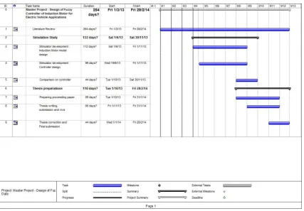
[image:16.595.115.543.211.508.2]Figure 1.2 shows the Gantt chart of overall project with estimated time to finish the whole project takes around 12 months.
CHAPTER 2
A BRIEF REVIEW ON PREVIOUS RESEARCH
2.1 INTRODUCTION
Figure 2.1: Hubbert peak oil plot, (photo courtesy of M. King Hubbert 1956)
2.2 INDUCTION MOTOR
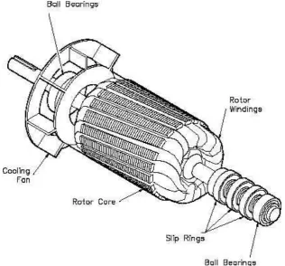
2.2.1 Construction and Operation
9
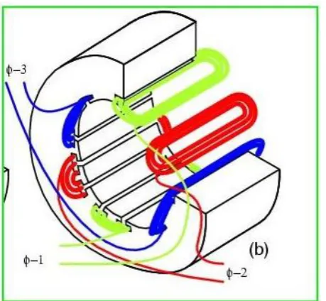
Figure 2.2: Stator construction of Induction Motor
Figure 2.3: Squirrel Cage Rotor constructions, (photo courtesy of www.tpub.com retrieved on 29 Nov 2013)
[image:20.595.161.478.384.678.2]11
The reason for having skewed rotor is as follow [4]:
1. It helps in reduction of magnetic hum, thus keeping the motor quiet, 2. It also helps to avoid ‘Cogging’, i.e. locking tendency of the rotor. The
tendency of rotor teeth remaining under the stator teeth due to the direct attraction between the two,
3. Increase in effective ratio of transformation between stator and rotor.
2.2.2 Principle of Rotating Magnetic Field
When a three phase voltage is applied to the stator winding, a rotating magnetic field is created. It is called a rotating field since its poles do not remain in a fixed position on the stator but go on shifting their positions surrounding the stator. It is also called synchronous because at steady state the speed of the rotor is the same as the speed of the rotating magnetic field in the stator. This field passes through the air-gap and cuts the stationary rotor conductors. Owing to the relative speed between the rotating flux and the static rotor, electromotive forces are induced in the rotor conductors. For the reason that the rotor circuit is short-circuited, currents start flowing in the rotor conductors. These currents interact with the rotating magnetic field created by the stator. As a result, mechanical force acts on the rotor conductors. A torque, produced as a result of this force, tends to move the rotor in the same direction as the rotating field. This is justified by Lenz’s law, according to which the direction of rotor currents will be such that they have a tendency to oppose the cause producing them. Now, the relative speed between the rotating field and the standstill rotor conductors is the cause generating the rotor currents. Thus to reduce this speed, the rotor starts running in the same direction as that of stator field and tries to catch it. Clearly, the rotor speed is always less than the stator field speed.
2.2.3 Applications of Induction Motor in Electric Vehicle
construction, simplicity in design and cost effectiveness [19-21]. Induction motors are seen as more rugged electric vehicle application compared to permanent magnet motors which are vulnerable to possible degradation or demagnetization of the magnets due to over-temperature or accidental over-current at power levels over 5kW [22]. Though induction motors have few advantageous characteristics, they also possess nonlinear and time-varying dynamic interactions [23-27], using conventional PI controller, it is very difficult and complex to design a high performance induction motor drive system. The fuzzy logic control (FLC) is attractive approach, which can accommodate motor parametric variations and difficulty in obtaining an accurate mathematical model of induction motor due to rotor parametric and load time constant variations.
2.3 CONTROLLER
There are two main parts in a control system and that is model based and non-model based. Motion control, adaptive structure control and signal processing control are the example of model based control where mathematical model is a must. While non-model based like artificial intelligence does not require the knowledge of the exact mathematical model. In this chapter fuzzy logic controller which one of the artificial intelligence is discusses. Block diagram of Fuzzy logic Controller along with the membership functions, Inference engine and various defuzzification techniques are presented. Fuzzy set theory and operations are also discussed in detail. Below is a few journals that proves Fuzzy logic controller performs better than conventional controllers.
13
2. Ashutosh Mishra (2012) in “Fuzzy Logic Controller for Speed Control of An Induction Motor (IM) using Indirect Vector Control Method” developed and implemented an intelligent controller for speed control of an induction motor (IM) using indirect vector control method. The comparative performance of Fuzzy Logic control technique has been presented and analysed. The present approach avoids the use of flux and speed sensor which increases the installation cost and mechanical robustness. The fuzzy logic controller is found to be useful techniques to obtain a high performance speed control.
3. Mohammed Shoeb Mohiuddin, Mahboob Alam (2013) in “Performance analysis of Fuzzy logic based speed control of DC motor” states that self-tuning FLC has better performance in both transient and steady state response and also has better dynamic response curve, shorter response time, small overshoot, small steady state error, high steady precision compared to the conventional PID controller.
One of the reasons for the popularity of Fuzzy Logic Controllers is its logical resemblance to a human operator. It operates on the foundations of a knowledge base which in turn rely upon the various if then rules, similar to a human operator. Unlike other control strategies, this is simpler as there is no complex mathematical knowledge required. The FLC requires only a qualitative knowledge of the system thereby making the controller not only easy to use, but also easy to design. The basic concepts of PI controllers along with the transfer functions and the block diagram are also being discussed in this chapter.
2.3.1 Introduction to Fuzzy Logic Controller
extended to deal with the concept of partial truth – truth values which exist between “completely true" and "completely false", and what we shall be referring to as fuzzy
logic. This is achieved through the concept of degree of membership. The essence of
fuzzy logic rests on a set of linguistic if-then rules, like a human operator. It has met a growing interest in many motor control applications due to its nonlinearity handling features and independence of plant modelling. Moreover, the fuzzy logic concepts play a vital role in developing controllers for the plant since it isn’t needy of the much complicated hardware and all it necessitates are only some set of rules. The advantages provided by a FLC are listed below [30]:
It is simple to design
It provides a hint of human intelligence to the controller. It is cost effective.
No mathematical modelling of the system is required. Linguistic variables are used instead of numerical ones. Non-linearity of the system can be handled easily.
These advantages allow fuzzy controllers can be used in systems where description of the process and identification of the process parameters with precision is highly difficult. Hence it provides a fuzzy characteristic to the control mechanism.
15
2.3.2 Application Areas of Fuzzy Logic Controllers
The fuzzy logic controllers are basically put to use when [30]:
1. The system is highly non-linear thereby making the mathematical modelling of the systems very arduous.
2. The analytical form of the system is not provided, instead a linguistic form is provided.
3. The precise identification of the system parameters.
4. The system behaviour has a vague characteristic under precisely defined conditions.
5. The conditions themselves are vague.
2.3.3 Components of FLC
The inputs to a Fuzzy Logic Controller are the processed with the help of linguistic variables which in turn are defined with the aid of membership functions. The membership functions are chosen in such a manner that they cover the whole of the universe of discourse. To avoid any discontinuity with respect to minor changes in the inputs, the adjacent fuzzy sets must overlap each other. Because of a small time constant in Fuzzy Logic Controllers, this criterion is very important in the design of the same.
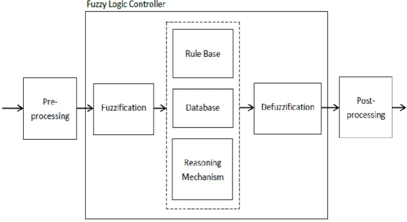
There are basically three essential segments in Fuzzy Logic Controller and the structure is shown as figure 2.5 [30]:
1. Fuzzification block of Fuzzifier 2. Inference System
Figure 2.5 Fuzzy Logic Controller Structure, (photo courtesy of El-Saady et al, 1994)
1. Fuzzification
17
2. Inference System
The inference system of a Fuzzy Logic Controller consists of the following three paradigms:
1. Rule Base: - It consists of a number of If-Then rules. The If side of the rule is called the antecedent and the Then side is called the consequence. These rules are very much similar to the human thought process and the computer uses the linguistic variables, derived after fuzzification for execution of the rules. They very simple to understand and write and hence the programming for the fuzzy logic controller becomes very simple. The control strategy is stored in more or less the normal language.
2. Database: - It consists of the all the defined membership functions that are to be used by the rules.
3. Reasoning Mechanism: - It performs the inference procedure on the rules and the data given to provide a reasonable output. It is basically the codes of the software which are process the rules and the all the knowledge based on a particular situation. It exercises a human brain type of attribute to methodically carry out the inference steps for processing the information.
3. Defuzzification
A defuzzifier performs the exact opposite function of a fuzzifier. It transforms the fuzzy variables (which are obtained as output after processing of the inputs) to crisp sets. The defuzzifier is necessary because in the real world the crisp values can only be taken as inputs to the other systems. Even though the fuzzy sets resemble the human thought process, their functionality is limited only to the above processes. A defuzzifier is generally required only when the Mamdani Fuzzy Model is used for designing a controller. There are other types of architectures that can be used are:
Mamdani model is preferred here because it follows the Compositional Rule of Inference strictly in its fuzzy reasoning mechanism. Unlike the Mamdani model, the outputs are defined with the help of a specific function for the other two models (first order polynomial in the input variables) and hence the output is crisp instead of fuzzy. This is counterintuitive since a fuzzy model should be able to propagate the fuzziness from inputs to outputs in an appropriate manner.
2.3.4 Designing Fuzzy Logic Controller
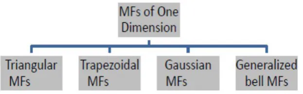
[image:28.595.154.466.432.529.2]Any membership function completely characterizes the fuzzy set that it belongs to. A convenient and succinct way to define an MF is to express it as a mathematical function. In order to define fuzzy membership function, designers choose many different shapes based on their preference and know how. Different classes of parameterized membership functions commonly used are:
Figure 2.6: Classes of Membership Functions
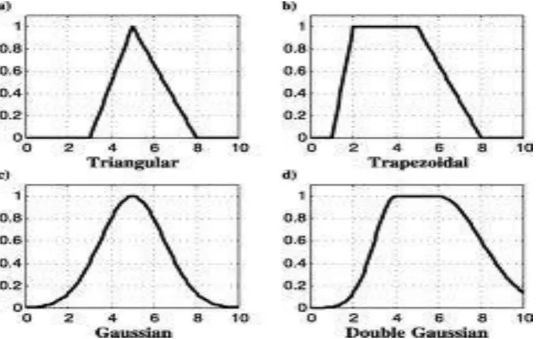
19
Figure 2.7: Examples of four classes on MF parameter, (photo courtesy of El-Saady et al, 1994)
CHAPTER 3
METHODOLOGY
3.1 INTRODUCTION
21
Figure 3.1: Electric vehicle Simulink model, adapted from Olivier Tremblay, Souleman Njoya Motapon, Louis-A. (2011), Fuel Cell Vehicle (FCV) Power Train
model
The FCV Electrical Subsystem is composed of four parts: The electrical motor, the battery, the fuel cell and the DC/DC converter.
The electrical motor is a 288 Vdc, 100 kW interior Permanent Magnet Synchronous Machine (PMSM) with the associated drive (based on AC6 blocks of the SimPowerSystems Electric Drives library). This motor has 8 pole and the magnets are buried (salient rotor's type). A flux weakening vector control is used to achieve a maximum motor speed of 12 500 rpm. The battery is a 13.9 Ah, 288 Vdc, 25 kW Lithium-Ion battery.
The fuel cell is a 400 cells, 288 Vdc, 100 kW Proton Exchange Membrane (PEM) fuel cell stack.
Figure 3.2: FCV Vehicle Dynamics Subsystem, adapted from Olivier Tremblay, Souleman Njoya Motapon, Louis-A. (2011), Fuel Cell Vehicle (FCV) Power Train
model
Figure 3.2 shows the FCV Vehicle Dynamics Subsystem that models all the mechanical parts of the vehicle:
The single reduction gear reduces the motor's speed to increase the torque. The differential splits the input torque into two equal torques.
The tires dynamics represent the force applied to the ground.
23
Figure 3.3: Energy Management Subsystem (EMS), adapted from Olivier Tremblay, Souleman Njoya Motapon, Louis-A. (2011), Fuel Cell Vehicle (FCV) Power Train
model
3.2 FLOW CHART
START
Literature Review
Designing of Induction Motor
Fuzzy Controller Design
PI Controller Design
Analysis on comparison of Both Controller
[image:34.595.160.478.103.676.2]END
43
REFERENCES
1. Wry, J.(2003). Electric Vehicle Technology Explained. Pp. 183-195, John Wiley & Sons, Ltd., ISBN 0-470-85163-5, UK
2. Q. Huang, J. Li and Y. Chan (2010). Control of Electric Vehicle, University of Science and Technology of China, ISBN 9789533071008, P.R. China 3. Abdullah I. Al-Odienat, Ayman A. Al-Lawama, “The Advantages of PID
Fuzzy Controllers Over The Conventional Types,” American Journal of Applied Sciences 5 (6):653-658, 2008, ISSN 1546-9239, pp. 653 – 658. 4. B.L. Theraja (1959). A Textbook of Electrical Technology. India: S. Chand.
1245-1250.
5. B.K.Bose, “Intelligent Control and Estimation in Power Electronics and Drives", IEEE International Electric Machines and Drives Conference Record, pp. TA2/2.1 -TA2/2.6, May 1997.
6. T.G.Habetler, R.G.Harley, “Power Electronic Converter and System Control” Proceedings of the IEEE, Vol.89, and Issue: 6, pp.913 –925, Jun 2001.
7. Ye Zhongming, Wu Bin, “A Review on Induction Motor Online Fault Diagnosis" The Third International Power Electronics and Motion Control Conference Proceedings. PIEMC 2000, Vol.3, pp.1353 -1358 vol.3, 2000. 8. M.R.Tamjis, W.P.Hew, M.R.Anas, W.A.Adnan, "Intelligent Electric Drive
System" TENCON 2000. Proceedings, Vol.3, pp.334 –335, 2000.
9. Poorani, S., Kumar, K.U.Renganarayanan S. (2003). Intelligent controller design for electric vehicle. Proc. 57th IEEE Semiannual Vehicular Technology Conf., pp. 2447 – 2450, Jeju, Korea, Apr. 2003
10.Khatun, P., Bingham, C.M., Schofield, N., Mellor, P.H. (2003). Application of fuzzy control algorithms for electric vehicle antilock braking/traction control systems. IEEE Trans. Vehicular Tech., Vol.52(5), 2003, pp. 1356 – 1364
12.C. Ta, C. Chakraborty, Y. Hori (2001). Efficiency maximization of induction motor drives for electric vehicles based on actual measurement of input power. IECON01 27th Annual Conf. of IEEE Industrial Electronics Society. Vol.3, pp. 1692-1697
13.Gosden, D.F., Chalmers, B.J., Musaba, L. (1994). Drive system design for an electric vehicle based on alternative motor types. IEEE Power Electronics and Variable-speed Drives Conference, pp. 710-715
14.Dave Rapini, “New directions in motor control”. Motion Control, Jan/Feb 1999, pp 37-38.
15.K.J. Astrom and T. Hagglund, “Advanced PID Control”, The Instrumentation, Systems, and Automation Society, 2005.
16.A. O’Dwyer, “Handbook of PI and PID controller tuning rules”, Imperial College Press, 2006.
17.Hubbert, Marion King (June 1956). "Nuclear Energy and the Fossil Fuels Drilling and Production Practice'" (PDF). Spring Meeting of the Southern District. Division of Production. American Petroleum Institute. San Antonio, Texas: Shell Development Company. pp. 22–27. Retrieved 18 April 2008. 18.Jump up Brandt, Adam R. (May 2007). "Testing Hubbert". Energy Policy
(Elsevier) 35 (5): 3074–3088. doi:10.1016/j.enpol.2006.11.004
19.G.J. Murphy, "Considerations in the design of drive systems for on-the-road electric vehicles," Proc. IEEE, vol.60, iss.12, Dec. 1972, pp. 1519-1533. 20.R. Krishnan, Electric Motor Drives - Modeling, Analysis, and Control,
Prentice Hall, NJ, 2001.
21.S.A. Nasar, Electric Machines and Power Systems, McGraw-Hill, 1995. 22.“Electric Drives - AC Motors (Description and Applications)”,
http://www.mpoweruk.com/motorsac.htm , retrieved on 20 Dec 2013
23.P.C. Krause, “Analysis of Electric Machinery”, McGraw-Hill, 1986
24.G.J.Klir and T.A.Floger,"Fuzzy SaUncertainty and 1nformation"Prentice Hall, Englewood Clifi,New Jney,U.S.A., 1988.
45
26.C.C.Lee,"Fuzzy Logic in Control System:Fuzzy Logic Controller-Part 11," IEEE Transactions on Systems,Man.and Cybemetics. V01.20. No.2, PP.419435, MarchiApril 1990.
27.N.T. M. M o b Undeland and W.P.Robbins,"Power Electronics Converter, Applications and Design"John Wiley&Sons Inc. Canada, 1989.
28.Ashutosh Mishra, Prashant Choudhary (2012), “Artificial Neural Network Based Controller for Speed Control of an Induction Motor using Indirect Vector Control Method”, International Journal of Power Electronics and Drive System (IJPEDS), Vol.2, No.4, December 2012, pp. 402~408.
29.Mohammed Shoeb Mohiuddin, Mahboob Alam (2013), “Performance analysis of Fuzzy logic based speed control of DC motor”, IOSR Journal of Electrical and Electronics Engineering (IOSR-JEEE), Volume 7, Issue 4 (Sep. - Oct. 2013), PP 17-24
30.El-Saady, G., Sharaf, a. M., Makky, a., Sherbiny, M. K., & Mohamed, G. (1994). A high performance induction motor drive system using fuzzy logic controller. Proceedings of MELECON ’94. Mediterranean Electrotechnical Conference, pp 1058–1061.
31.T.A.Lipo and P.C. Krause, Stability Analysis of a Rectifier-Inverter Induction Motor Drive, IEEE Trans. On Power Apparatus and Systems, vol. PAS-88, 1969, pp. 55-66
32.W. Rippel (9-1-2007) “Induction Versus DC Brushless Motors”, http://www.teslamotors.com , retrieved on 30th May 2013
33.A. Wibowo, H. Mauridhi, T. Hiyama (2010). Speed Control of Induction Motor based on direct torque control using Neural Network self-tuning sliding mode control for electric car drive.
34.R.E. Janzen and N.C. Kar (2006). Efficiency Improvements from an electric vehicle induction motor drive, with augmentations to a PI control. IEEE CCECE ’06, pp. 1228 - 1231
35.Ch.N.K. Kumar, P.L.Reddy, K. Trinath, S. Sundeep, A.S. Kumar (2011). Modelling and controlling of induction motor by using linear ADRC. IJEST Vol.3 pp. 2740 – 2745
37.John Voelcker (2012-12-07). "Tesla Model S 60-kWh Version: EPA Range Rated At 208 Miles", http://teslachannels.com. Green Car Reports, retrieved on 30th May 2013
38.www.thinkev.com, retrieved on 30th May 2013
39.Patrice Brunell (17 Oct 2011), Fuel Cell Vehicle (FCV) Power Train model, Matlab File, Retrieved on 5 June 2012