International Journal of Emerging Technology and Advanced Engineering
Website: www.ijetae.com (ISSN 2250-2459, Volume 2, Issue 7, July 2012)
An Efficient Power Consumption MAC Protocol in MANET
Rahul Mukherjee
HOD and Assistant Professor, Electronics & Communication Department,St. Aloysius Institute of Technology (SAIT), Jabalpur, India
Abstract - Mobile Ad-hoc Network (MANET) is a self configuring infrastructure-less network of mobile devices connected by wireless They have undergone rapid growth in the past several years because of their application in military and rescue service, disaster recovery operations, mobile conferencing and many other applications. The Media Access Control (MAC) data communication protocol sub-layer provides addressing and channel access control mechanisms that make it possible for network nodes to access common wireless channel through distributed coordination function (DCF).
This work proposes a new power controlled MAC protocol based on IEEE 802.11. It saves considerable amount of power and achieves the performance matching with that of IEEE 802.11.
Keywords - MANET, 802.11 MAC, Distributed Coordination Function (DCF), Point Coordination Function (PCF), CSMA (Carrier Sense Multiple Access)
I. INTRODUCTION
Mobile Ad-hoc networks are collections of mobile nodes, dynamically forming a temporary network without pre-existing network infrastructure or centralized administration. These nodes can be arbitrarily located and are free to move randomly at any given time, thus allowing network topology and interconnections between nodes to change rapidly and unpredictably. As MANET networks are infrastructure less there exist no dedicated routers. Instead, every mobile node acts itself as a router and is also responsible for discovering and maintaining routes.
[image:1.595.323.531.316.474.2]In the 802.11 protocol, the fundamental mechanism to access the medium is called Distributed Coordination. Function (DCF). This is a random access scheme, based on the Carrier Sense Multiple Access with Collision Avoidance (CSMA/CA) protocol.
Figure .1. Ad-hoc Wireless Network
II. HIDDEN AND EXPOSED NODE PROBLEMS
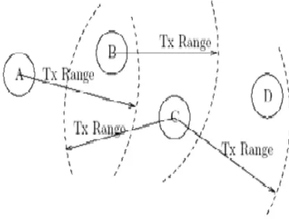
[image:1.595.56.273.618.745.2]The transmission range of stations in wireless network is limited by the transmission power; therefore, all the station in a LAN cannot listen to each other. This means that normal carrier sense mechanism which assumes that all stations can listen to each other, fails. In particular, this gives rise to hidden node and exposed node problem. Consider stations A, B, C and D as shown in figure.
Figure .2. Hidden & Exposed node problem
III. CSMA/CA
The most important part of a MAC protocol is Channel Access Mechanism. The channel access mechanism is way of regulating the use of physical channel among the stations present in the network. It specifies when a station can send or receive data on the channel.
International Journal of Emerging Technology and Advanced Engineering
Website: www.ijetae.com (ISSN 2250-2459, Volume 2, Issue 7, July 2012)Figure .3. CSMA Channel Access Mechanism
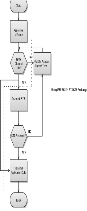
CSMA/CA is asynchronous mechanism for medium access and does not provide any bandwidth guarantee. It’s a best effort service and is suited for packetized applications like TCP/IP. It adapts quite well to the variable traffic conditions and is quite robust against interference.
Figure .4. Flow chart of CSMA/CA
IV. CLASSIFICATION OF MAC PROTOCOL
MAC protocols for ad-hoc wireless networks can be classified into several categories based on various criteria such as initiation approach, time synchronization, and reservation approach. Ad-hoc Network MAC protocols are classified in three types;
Contention based protocols.
Contention based protocols with reservation mechanism.
Contention based protocols with scheduling mechanism.
A.Contention Based Protocols
These protocols follow a contention based channel access policy. A node doesn’t make any resource reservation in priori. Whenever it receives a packet to be transmitted, it contends with other nodes for access to the shared channel. These are further divided into two types;
Sender initiated protocols
Receiver initiated protocols
B.Contention Based Protocol with Reservation Mechanisms
Ad-hoc wireless networks sometimes may need to support real time traffic, which requires QoS guarantees to be provided. In order to support such traffic, certain protocols have mechanism for reserving bandwidth in priori. These protocols are classified into two types;
Synchronous protocols
Asynchronous protocols
C.Contention Based Protocol with Scheduling Mechanisms
These protocols focus on packet scheduling at nodes, and also scheduling nodes for access to the channel. Node scheduling is done in a manner so that all nodes are treated fairly. Scheduling based scheme are also used for enforcing priorities among flows whose packets are queued at nodes.
V. IEEE 802.11 OPERATION
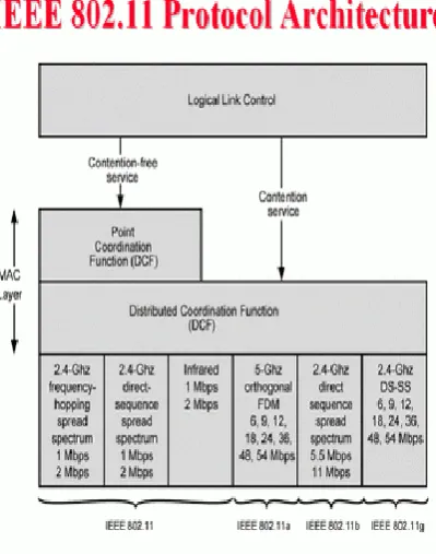
The IEEE 802.11 MAC offers two kinds of medium access methods, namely Distributed Coordination Function (DCF), and Point Coordination Function (PCF). DCF is the basic access method in 802.11 and requires no infrastructure.
[image:2.595.122.263.400.741.2]International Journal of Emerging Technology and Advanced Engineering
Website: www.ijetae.com (ISSN 2250-2459, Volume 2, Issue 7, July 2012) [image:3.595.323.523.162.416.2]Many BSSs may be connected by a Distribution System (DS) to form an Extended Service Set (ESS). An access point (AP) is the station that provides access to DS services.
Figure .5. MAC Architecture
The IEEE 802.11 MAC is designed for wireless LANs. The requirements of multi-hop ad-hoc networks are more challenging than those of wireless LANs. In this research, we investigate the operation of IEEE 802.11 MAC in centralized multi-hop ad-hoc networks. The terms station and node are used interchangeably throughout the thesis. Multi-hop cooperative wireless ad-hoc networks will be simply referred to as multi-hop networks.
Figure .6. Multi-hop Scenario
Consider a multi-hop centralized scenario, as shown in the figure. For convenience, the stations inside the network are classified into following categories:
Central station : is the central controlling station. Most of the traffic in the network is directed towards it.
Inner stations : are within one hop boundary of the central station.
[image:3.595.48.284.194.351.2]Boundary stations : are at one hop boundary of the central station. These stations act as relaying stations for the stations outside the reach of central node. Outer stations are outside the communication range of central node.
Figure .7. IEEE 802.11 Architecture
VI. IEEE 802.11 SCHEME SPECIFICATION
IEEE 802.11 specifies two medium access control protocols, PCF (Point Coordination Function) and DCF (Distributed Coordination Function). PCF is a centralized scheme, whereas DCF is a fully distributed scheme. We consider DCF in this paper.
Transmission range : When a node is within transmission range of a sender node, it can receive and correctly decode packets from the sender node. In our simulations, the transmission range is 250 m when using the highest transmit power level.
Carrier sensing range : Nodes in the carrier sensing range can sense the sender’s transmission. Carrier sensing range is typically larger than the transmission range, for instance, two times larger than the transmission range. In our simulations, the carrier sensing range is 550 m when using the highest power level. Note that the carrier sensing range and transmission range depend on the transmit power level.
[image:3.595.51.280.455.594.2]International Journal of Emerging Technology and Advanced Engineering
Website: www.ijetae.com (ISSN 2250-2459, Volume 2, Issue 7, July 2012) [image:4.595.316.566.213.379.2]Nodes in the transmission range can indeed sense the transmission, but they can also decode it correctly. Therefore, these nodes will not be in the carrier sensing zone as per our definition. The carrier sensing zone is between 250 m and 550 m with the highest power level in our simulation.
Figure .8. Carrier Sensing
VII. MAC SUB LAYER IN IEEE 802.11
The IEEE standard 802.11 specifies the most famous family of WLANs in which many products are already available. Standard belongs to the group of 802.x LAN standards, e.g., 802.3 Ethernet or 802.5 Token Ring. This means that the standard specifies the physical and medium access layer adapted to the special requirements of wireless LANs, but offers the same interface as the others to higher layers to maintain interoperability.
SYSTEM ARCHITECTURE
The basic service set (BSS) is the fundamental building block of the IEEE 802.11 architecture. A BSS is defined as a group of stations that are under the direct control of a single coordination function (i.e., a DCF or PCF) which is defined below. The geographical area covered by the BSS is known as the basic service area (BSA), which is analogous to a cell in a cellular communications network.
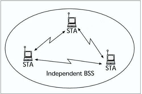
Conceptually, all stations in a BSS can communicate directly with all other stations in a BSS. However, transmission medium degradations due to multipath fading, or interference from nearby BSSs reusing the same physical-layer characteristics (e.g., frequency and spreading code, or hopping pattern), can cause some stations to appear hidden from other stations. An ad hoc network is a deliberate grouping of stations into a single BSS for the purposes of internetworked communications without the aid of an infrastructure network.
[image:4.595.61.276.215.437.2]Given figure is an illustration of an independent BSS (IBSS), which is the formal name of an ad hoc network in the IEEE 802.11 standard. Any station can establish a direct communications session with any other station in the BSS, without the requirement of channeling all traffic through a centralized access point (AP).
Figure .9. System Architecture of an Ad-hoc network
In contrast to the ad hoc network, infrastructure networks are established to provide wireless users with specific services and range extension. Infrastructure networks in the context of IEEE 802.11 are established using APs. The AP is analogous to the base station in a cellular communications network. The AP supports range extension by providing the integration points necessary for network connectivity between multiple BSSs, thus forming an extended service set (ESS). The ESS has the appearance of one large BSS to the logical link control (LLC) sub layer of each station (STA). The ESS consists of multiple BSSs that are integrated together using a common distribution system (DS). The DS can be thought of as a backbone network that is responsible for MAC-level transport of MAC service data units (MSDUs).
[image:4.595.316.552.584.750.2]International Journal of Emerging Technology and Advanced Engineering
Website: www.ijetae.com (ISSN 2250-2459, Volume 2, Issue 7, July 2012)VIII. DCF OPERATION
The DCF is the fundamental access method used to support asynchronous data transfer on a best effort basis. The DCF is based on CSMA/CA. The carrier sense is performed at both the air interface, referred to as physical carrier sensing, and at the MAC sub layer, referred to as virtual carrier sensing. Physical carrier sensing detects presence of other users by analyzing the activity in the channel through the received signal strength.
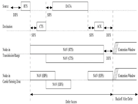
[image:5.595.322.559.278.458.2]A station performs virtual carrier sense by examining the received MPDU (MAC Protocol Data Unit) information in the header of RTS, CTS and ACK frames. The stations in BSS use this information to adjust their Network Allocation Vector (NAV), which indicates amount of time that must elapse until the current transmission is complete and the channel can be sampled again for idle status.
Figure .11. DCF access using RTS/CTS
A.Inter frame Spacing
IFS is the time interval between frames. IEEE 802.11 defines four IFSs – SIFS (short inter frame space), PIFS (PCF inter frame space), DIFS (DCF inter frame space), and EIFS (extended inter frame space). The IFSs provide priority levels for accessing the channel. The SIFS is the shortest of the inter frame spaces and is used after RTS, CTS, and DATA frames to give the highest priority to CTS, DATA and ACK, respectively. In DCF, when the channel is idle, a node waits for the DIFS duration before transmitting any packet.
In figure, nodes in transmission range correctly set their NAVs when receiving RTS or CTS. However, since nodes in the carrier sensing zone cannot decode the packet, they do not know the duration of the packet transmission. To prevent a collision with the ACK reception at the source node, when nodes detect a transmission and cannot decode it, they set their NAVs for the EIFS duration. The main purpose of the EIFS is to provide enough time for a source node to receive the ACK frame, so the duration of EIFS is longer than that of an ACK transmission.
As per IEEE 802.11, the EIFS is obtained using the SIFS, the DIFS, and the length of time to transmit an ACK frame at the physical layer’s lowest mandatory rate, as the following equation :
EIFS = SIFS + DIFS + [(8·ACKsize) + Preamble Length + PLCP Header Length] / Bit Rate
where ACK size is the length (in bytes) of an ACK frame, and Bit Rate is the physical layer’s lowest mandatory rate. Preamble Length is 144 bits and PLCP Header Length is 48 bits . Using a 1 Mbps channel bit rate, EIFS is equal to 364 μs.
Figure .12. NAV duration in transmission range and carrier sensing zone
IX. ASIC POWER CONTROL PROTOCOL
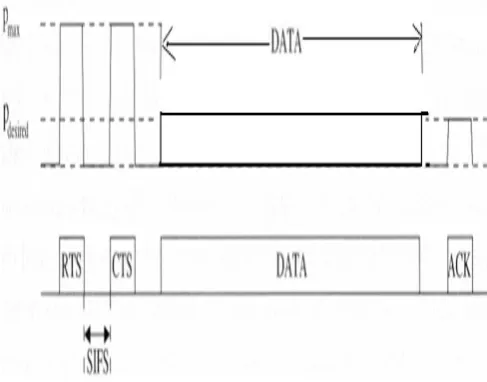
[image:5.595.55.290.356.521.2]Figure shows nodes A and B send RTS and CTS, respectively, with the highest power level so that node C receives the CTS and defers its transmission. By using a lower power for DATA and ACK packets, nodes can conserve energy.
Figure .13. Basic Scheme.
[image:5.595.329.559.586.717.2]International Journal of Emerging Technology and Advanced Engineering
Website: www.ijetae.com (ISSN 2250-2459, Volume 2, Issue 7, July 2012)
Suppose that node A wants to send a packet to node B. Node A transmits the RTS at power level pmax. When B receives the RTS from A with signal level pr, B can calculate the minimum necessary transmission power level, pdesired, for the DATA packet based on received power level pr, the transmitted power level, pmax, and noise level at the receiver B.We can borrow the procedure for estimating pdesired from. This procedure determines pdesired taking into account the current noise level at node B. Node B then specifies pdesired in its CTS to node A. After receiving CTS, node A sends DATA using power level pdesired. Since the signal-to-noise ratio at the receiver B is taken into consideration, this method can be accurate in estimating the appropriate transmit power level for DATA.
In the second alternative, when a destination node receives an RTS, it responds by sending a CTS as usual (at power level p max). When the source node receives the CTS, it calculates p desired based on received power level, pr, and transmitted power level (p max), asP desired = p max/pr · Rxthresh · c,
[image:6.595.319.557.441.663.2]where Rxthresh is the minimum necessary received signal strength and c is a constant. We set c equal to 1 in our simulations. Then, the source transmits DATA using a power level equal to p desired. Similarly, the transmit power for the ACK transmission is determined when the destination receives the RTS.
Figure .14. Basic Power Control Protocol.
X. DEFICIENCY OF THE BASIC PROTOCOL
In the Basic scheme, RTS and CTS are sent using pmax, and DATA and ACK packets are sent using the minimum necessary power to reach the destination. When the neighbour nodes receive an RTS or CTS, they set their NAVs for the duration of the DATA–ACK transmission. When D and E transmit the RTS and CTS, respectively, B and C receive the RTS, and F and G receive the CTS, so these nodes will defer their transmissions for the duration of the D–E transmission.
Node A is in the carrier sensing zone of D (when D transmits at pmax) so it will only sense the signals and cannot decode the packets correctly. Node A will set its NAV for EIFS duration when it senses the RTS transmission from D. Similarly, node H will set its NAV for EIFS duration following CTS transmission from E.
When transmit power control is not used, the carrier sensing zone is the same for RTS–CTS and DATA–ACK since all packets are sent using the same power level. However, in Basic, when a source and destination pair decides to reduce the transmit power for DATA–ACK, the transmission range for DATA–ACK is smaller than that of RTS–CTS; similarly, the carrier sensing zone for DATA–ACK is also smaller than that of RTS–CTS.
[image:6.595.48.292.474.665.2]International Journal of Emerging Technology and Advanced Engineering
Website: www.ijetae.com (ISSN 2250-2459, Volume 2, Issue 7, July 2012)XI. PROPOSED POWER CONTROL MAC PROTOCOL
Proposed power control MAC (PCM) is similar to the Basic scheme in that it uses power level pmax for RTS–CTS and the minimum necessary transmit power for DATA–ACK transmissions. We now describe the procedure used in PCM.
1. Source and destination nodes transmit the RTS and CTS using pmax. Nodes in the carrier sensing zone set their NAVs for EIFS duration when they sense the signal and cannot decode it correctly.
2. The source node may transmit DATA using a lower power level, similar to the BASIC scheme.
3. To avoid a potential collision with the ACK (as discussed earlier), the source node transmits DATA at the power level pmax, periodically, for just enough time so that nodes in the carrier sensing zone can sense it. 4. The destination node transmits an ACK using the
minimum required power to reach the source node, similar to the BASIC scheme.
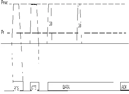
[image:7.595.60.276.466.624.2]Figure shows how the transmit power level changes during the sequence of an RTS–CTS–DATA–ACK transmission. After the RTS–CTS handshake using pmax, suppose the source and destination nodes decide to use power level p1 for DATA and ACK. Then, the source will transmit DATA using p1 and periodically use pmax. The destination uses p1 for ACK transmission.
Figure .16. PCM periodically increases
The key difference between PCM and the Basic scheme is that PCM periodically increases the transmit power to pmax during the DATA packet transmission. With this change, nodes that can potentially interfere with the reception of ACK at the sender will periodically sense the channel as busy, and defer their own transmission.
Since nodes that can sense a transmission but not decode it correctly only defer for EIFS duration, the transmit power for DATA is increased once every EIFS duration. Also, the interval which the DATA is transmitted at pmax should be larger than the time required for physical carrier sensing.
Accordingly, 15 μs should be adequate for carrier sensing, and time required to increase output power (power on) from 10% to 90% of maximum power (or power-down from 90% to 10% of maximum power) should be less than 2 μs. Thus, we believe 20 μs should be enough to power up (2 μs), sense the signal (15 μs), and power down (2 μs). In our simulation, EIFS duration is set to 212 μs using a 2 Mbps bit rate. In PCM, a node transmits DATA at pmax every 190 μs for a 20 μs duration. Thus, the interval between the transmissions at pmax is 210 μs, which is shorter than EIFS duration. A source node starts transmitting DATA at pmax for 20 μs and reduces the transmit power to a power level adequate for the given transmission for 190 μs. Then, it repeats this process during DATA transmission. The node also transmits DATA at pmax for the last 20 μs of the transmission.
With the above simple modification, PCM overcomes the problem of the BASIC scheme and can achieve throughput comparable to 802.11, but uses less energy.
International Journal of Emerging Technology and Advanced Engineering
Website: www.ijetae.com (ISSN 2250-2459, Volume 2, Issue 7, July 2012)Figure .17. Flow chart of Proposed Protocol
XII. SIMULATION RESULTS
The given table shows all the different parameters taken into account for conducting the simulation in NS-2 atmosphere. In this table the values of all the different parameters are shown, using which the simulation for aggregate throughput and total data delivered per joule in accordance with Data rate per flow and Packet size is calculated for all three schemes namely, BASIC, 802.11 and Proposed protocol’s.
A.Simulation Result for Aggregate Throughput vs Data Rate Per Flow
International Journal of Emerging Technology and Advanced Engineering
Website: www.ijetae.com (ISSN 2250-2459, Volume 2, Issue 7, July 2012)C.Simulation Result for Data Delivered per Joule vs Data rate per flow
D.Simulation Result for Data Delivered per joule vs Packet Size
XIII. CONCLUSION
It is shown that the Basic scheme increases collisions and retransmissions, which can result in more energy consumption and throughput degradation. Hence, the proposed protocol is more efficient than Basic scheme and 802.11 yielding better throughput.
XIV. SUGGESTION FOR FUTURE WORK
We have shown the throughput of proposed protocol comparable to 802.11 with less power consumption for random topology ad hoc network.
In future the same power consumption scheme will be conducted for grid topology.
One possible approach to the mobile ad hoc network power control scheme is that, it is only applied to the Random topology ad hoc scenario but it can also be made applicable for Grid Topology power control scheme without degrading the network throughput. Where the nodes will be placed sequentially in a proper manner i.e, in an arranged fashion.
REFERENCES
[1 ] “Performance Analysis of the Binary Exponential Backoff Algorithm for IEEE 802.11 Based Mobile Ad Hoc Network”, Yi Hua Zhu, Xian-Zhong Tian and Jun Zheng, School of Computer Science and Technology, IEEE Communications , IEEE ICC 2011. [2 ] Vadiya, Nitin H., “Mobile Ad Hoc Networks: Routing, MAC and
Transport Issues”, MobiComm 2001 Tutorial, Rome, IT, pp. 1-431, July 2001.
[3 ] R. Wattenhofer, L. Li, P. Bahl and Y.-M. Wang, Distributed topology control for power efficient operation in multihop wireless ad hoc networks,Vol. 3 pp. 1388–1397 (April 2001).
[4 ] N. Poojary, S.V. Krishnamurthy and S. Dao, Medium access control in a network of ad hoc mobile nodes with heterogeneous power capabilities, in: Proc. IEEE International Conference on Communications (ICC 2001), Vol. 3 pp. 872–877 (2001). [5 ] IEEE 802.11 standard, “Wireless LAN Medium Access Control
(MAC) and Physical Layer specifications” IEEE std. June 1999. [6 ] S.-L.Wu, Y.-C. Tseng, C.-Y. Lin and J.-P. Sheu, A multi-channel
MAC protocol with power control for multi-hop mobile ad hoc networks, The Computer Journal (SCI) 45(1) 101–110 (2002). [7 ] Imrich Chlamtac, Macro Conti, Jennifer, Mobile ad hoc
networking : imperatives and challenges, School of engineering, University of Texas at Dallas, USA, Ad-Hoc Networks 1 (2003).
International Journal of Emerging Technology and Advanced Engineering
Website: www.ijetae.com (ISSN 2250-2459, Volume 2, Issue 7, July 2012)