© 2017, IRJET | Impact Factor value: 5.181 | ISO 9001:2008 Certified Journal | Page 542
A Review on Implementation of UPFC for improvement of active power
flow capability in power system using IEEE 14 bus system
Miss. Suvarna V. Patil
1, Prof. Kalpesh Mahajan
21
M.E. Student, Department of Electrical Engineering, KCE’s COEIT, Jalgaon, Maharashtra, India
2
H.O.D, Department of Electrical Engineering, KCE’s COEIT, Jalgaon, Maharashtra, India
---***---Abstract -
Flexible AC Transmission System (FACTS)Flexible alternating current transmission systems (FACTS) technology opens up new opportunities for controlling power and enhancing the usable capacity of present, as well as new and upgraded lines.. The Unified Power Flow Controller (UPFC) is a Flexible AC transmission system (FACTS) uses the thyristor controlled devices that can control all the three system variables namely can change parameters like impedance, voltage and phase angle difference of voltage across the line. For governing, UPFC is the most complex but promising power electronics system. This paper presents control and performance of Unified Power Flow Controller (UPFC) is investigated in controlling the flow of power over the transmission line. It can be present real and reactive power flow control through a transmission line by place Unified Power Flow Controller is studied to improve the power flow over a transmission line in a standard IEEE 14 bus system.
Key Words: FACTS, real and reactive power flow, IEEE 14 bus
system, IGBT, UPFC
1. INTRODUCTION
The Flexible ac transmission a system (FACTS) is the combination of the power “electronics” devices to controls the power flow and the quantities in power system. Its first concept was introduced by N.G Hingorani, in 1988 (FACTS) is very popular and essential device in power systems [1].
In order to have a better use of the transmission capabilities of the transmission lines, different types of FACTS devices have been studied: Static VAR Compensator (SVC), Thyristor controlled series capacitor (TCSC),Static synchronous compensator (STATOM), Static series compensator (SSSC), Unified Power Flow Controllers (UPFCs), thyristor switched capacitor (TSC) thyristor controlled reactor (TCR) [4-12]. Several FACTS-devices have been introduced for various applications in power system.
UPFC is the most flexible multi-functional FACTs device which is a new generation of FACTS devices proposed by Gyugyi in 1991. UPFC is a Combined Series-Shunt Controllers. The UPFC is one of the most versatile devices. In interconnected power systems, it is important to have control over power transfer [5]. This can improve stability and allow transmission lines to be loaded closer to their
thermal limits. In UPFC, the transmitted power can be controlled by changing three parameters of power transmission line namely transmission magnitude voltage, impedance and phase angle.
This device combination of two other FACTS devices: the Static Synchronous Compensator (STATCOM) and the Static Synchronous Series Compensator (SSSC). Practically, these two devices are two Voltage Source Inverters (VSI’s) connected respectively in shunt with the transmission line through a shunt transformer and in series with the transmission line through a series transformer. These are connected to each other by a common DC link, which is a typical storage capacitor [7-12].
2. LITERATURE REVIEW
Tanushree Kaul, Pawan Rana et. al. 2013[12] In the recent years ecological concerns and high installation costs have put constraints over construction of new plants and overhead lines in many countries, thereby forcing existing system to be used more efficiently rather than constructing new lines, industry has tended towards the development of technologies or devices that increase transmission network capacity while maintaining or even improving grid stability. Our main objective is to meet the electric load demand reliably while simultaneously satisfying certain quality constraints imposed on the power supply.
© 2017, IRJET | Impact Factor value: 5.181 | ISO 9001:2008 Certified Journal | Page 543
Kunal Gupta, Baseem Khan et. Al. 2015 The Flexible actransmission system is the combination of the power “electronics” devices to controls the power flow and the quantities in power system. The FACTS controllers are used to improve the utilization of the power system and improve its stability. FACTS provide the corrections of transmission functions to fully utilize existing transmission system. It has the capability to increase the transmission capacities to the required level FACTS device can be an alternative to reduce the flows in heavily loaded lines, resulting in increased load ability, low system loss, improved stability of the network, reduced cast of production and fulfiller contractual requirement by controlling the power flows in the network.
Sadjad Galvani, Mehrdad Tarafdar Hagh et. Al. 2014 unified power flow controller (UPFC) operation which can accurately reflect the impact of UPFC on power system steady security. Economic benefit of installing an static synchronous series compensator (SSSC) and adding a new transmission line to power system considering equipment availability and load uncertainty. In addition, application of flexible alternative current transmission systems (FACTS) controllers is obvious and has been considered in various aspects of system operation and planning problems such as system reliability increasing, fuel cost and loss minimization, improvement of system load ability, voltage stability increasing.
3. FACTS CONTROLLER
FACTS are powerful devices to improve the voltage
profile and power system enhancement. IEEE definition of FACTS Page Layout and FACTS controllers are given as. Flexible AC Transmission System (FACTS): Alternating current transmission systems incorporating power electronics based and other static controllers to enhance controllability and increase power transfer capability. The FACTS controllers are used to improve the utilization of the power system and improve its stability.FACTS device can be an alternative to reduce the flows in heavily loaded lines, resulting in increased load ability, low system loss, improved stability of the network. FACTS Controller FACTS controllers can be used for various applications to enhance power system performance. One of the greatest advantages of using FACTS controllers is that it can be used in all the three states of the power system, namely:
(i) Steady state, (ii) Transient,
(iii) Post transient steady state.
FACTS controllers are used for the dynamic control of voltage, impedance and phase angle of high voltage AC transmission lines. These FACTS controllers are based on voltage source converters. Thus, FACTS can facilitate the power flow control, enhance the power transfer capability,
decrease the generation cost, and improve the security and stability of the power system. FACTS controllers can be divided into four categories,
i) Series Controllers (SSSC,TSSC) ii) Shunt Controllers (SVC,STATCOM)
iii) Combined Series-Series Controllers (IPFC) iv) Combined Series-Shunt Controllers (UPFC)
4. UNIFIED POWER FLOW CONTROLLER
UPFC is the most flexible multi-functional FACTs device which is a new generation of FACTS devices. The UPFC is one of the most versatile devices. In UPFC, the transmitted power can be controlled by changing three parameters of power transmission line namely transmission magnitude voltage, impedance and phase angle.
4.1 Construction of UPFC
The UPFC consists of two voltage source converters; series and shunt converter, which are connected to each other with a common dc link. Shunt converter (converter 1)or Static Synchronous Compensator (STATCOM) is used to provide reactive power to the ac system, besides that, it will provide the dc power required for both inverters, while series converter (converter 2)or Static Synchronous Series Compensator (SSSC) is used to add controlled voltage magnitude line as shown in fig. 1. Each of the branches consists of a transformer and power electronic converter. These two voltage source converters shared a common dc capacitor. The real power can freely flow in either direction between the ac terminals of the two converters. In this respect, converter 2 provides the main function by injecting an AC voltage Vse, at system frequency with variable magnitude |Vse|, (|Vse| ≤ 0 ≤ |Vse| max) and phase angle (0 ≤ γ ≤ 2π) in series with the line. On the other hand, converter1 is used primarily to provide the real power demanded by converter2 at the common dc link [4].
[image:2.595.312.551.613.740.2]The energy storing capacity of this dc capacitor is generally small. The reactive power in the shunt or series converter can be chosen independently, giving greater flexibility to the power flow control.
© 2017, IRJET | Impact Factor value: 5.181 | ISO 9001:2008 Certified Journal | Page 544
4.2 Operation of UPFC
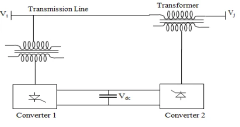
The Implementation of the UPFC using two back-to-back VSCs with a common dc-terminal capacitor. Fig. 2 Shows schematic diagram of the UPFC connected to the transmission line.
It comprises two VSCs coupled through a common dc terminal. One VSC—converter 1—is connected in shunt with the line through a coupling transformer; the other VSC— converter 2—is inserted in series with the transmission line through an interface transformer. The dc voltage for both converters is provided by a common capacitor bank. The series converter is controlled to inject a voltage pharos, Vpq, in series with the line, which can be varied from 0 to Vpq max. Moreover, the phase angle of Vpq can be independently varied from 0 degree to 360 degree [9].
In this process, the series converter exchanges both real and reactive power with the transmission line. Although the series converter, the real is made feasible by the dc energy storage device that is, the capacitor. The shunt-connected converter 1 is used mainly to supply the real-power demand of converter 2, which it derives from the transmission line itself. The shunt converter maintains constant voltage of the dc bus. Thus the net real power drawn from the ac system is equal to the losses of the two converters and their coupling transformers.
Fig -2: Schematic diagram of the UPFC connected to the transmission line
In addition, the shunt converter function like a STATCOM and independently regulates the terminal voltage of the interconnected bus by generating absorbing a requisite amount of reactive power. The concepts of various power-flow control functions by use of the UPFC are illustrated in Figs.3 (a)–(d) [2].
Fig -3: Basic UPFC control function. (a) Series compensation (b) Voltage Regulation (c) Angle regulation (d) Multi-function power flow controller
Part (a) depicts the addition of the general voltage phasor Vpq to the existing bus voltage, V0, at an angle that varies from 0 to 360. Voltage regulation is affected if Vpq (c DV0) is generated in phase with V0, as shown in part (b). A combination of voltage regulation and series compensation is implemented in part (c), where Vpq is the sum of a voltage regulating component DV0 and a series compensation providing voltage component Vc that lags behind the line current by 908. In the phase-shifting process shown in part (d), the UPFC-generated voltage Vpq is a combination of voltage-regulating component DV0 and phase-shifting voltage component Va. The function of Va is to change the phase angle of the regulated voltage Phasor, V0 + DV, by an angle a.
The UPFC is the most versatile and complex of the FACTS devices, combining the features of the STATCOM and the SSSC. The UPFC can provide simultaneous control of all basic power system parameters, viz., transmission voltage, impedance and phase angle. It is recognized as the most sophisticated power flow controller currently, and probably the most expensive one. In this paper, a UPFC control system that includes both the shunt converter and the series converter has been simulated. The performance of the UPFC in real and reactive power flow through the transmission line has been evaluated.
[image:3.595.40.284.445.714.2]© 2017, IRJET | Impact Factor value: 5.181 | ISO 9001:2008 Certified Journal | Page 545
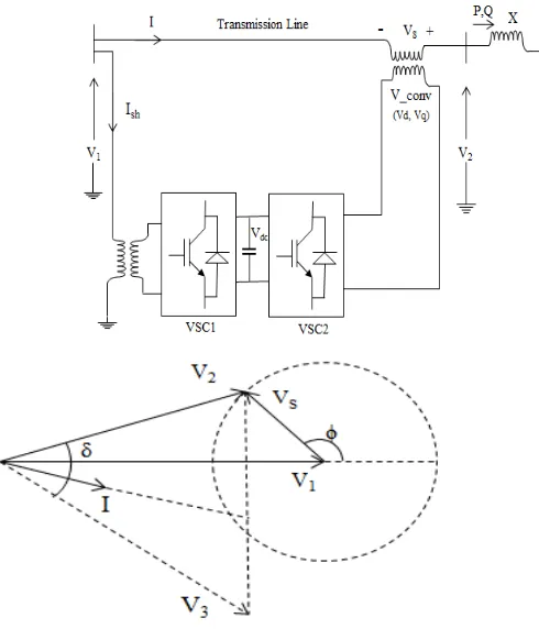
Fig – 4: Single line diagram of UPFC and Phasor ofVoltage and current
As the angle φ varies, the phase shift δ between V2 and V3 also varies. Voltage and current with the presence of the two converters, UPFC not only can supply reactive power but also active power. The equation for the active and reactive power is given as follows,
5. OPERATING MODES OF UPFC
The UPFC has many possible operating modes. In particular, the shunt inverter is operating in such a way to inject a controllable current, is, into the transmission line [6-9].The shunt inverter can be controlled in two different modes:
5.1 VAR Control Mode:
The reference input is an inductive or capacitive VAR request. The shunt inverter control translates the var reference into a corresponding shunt current request and adjusts gating of the inverter to establish the desired current. For this mode of control a feedback signal representing the dc bus voltage, Vdc, is also required.
5.2 Automatic Voltage Control Mode:
The shunt inverter reactive current is automatically regulated to maintain the transmission line voltage at the point of connection to a reference value. For this mode of control, voltage feedback signals are obtained from the sending end bus feeding the shunt coupling transformer. The series inverter controls the magnitude and angle of the voltage injected in series with the line to influence the power flow on the line. The actual value of the injected voltage can be obtained in several ways.
5.3 Direct Voltage Injection Mode:
The reference inputs are directly the magnitude and phase angle of the series voltage.
5.4 Phase Angle Shifter Emulation Mode:
The reference input is phase displacement between the sending end voltage and the receiving end voltage.
5.5 Line Impedance Emulation Mode:
The reference input is an impedance value to insert in series with the line impedance.
5.6 Automatic Power Flow Control Mode:
The reference inputs are values of P and Q to maintain on the transmission line despite system changes.
6. IMPLEMENTATION OF UPFC
The concept of the control system, in a transmission line is taken to implement the use of UPFC. The two control modes that is voltage injection mode and the power flow control mode to see the effect of UPFC on a transmission line. It is carried out to verify the utility of UPFC device. The UPFC could be considered as comprehensive reactive power and real power compensation capable of independently controlling the real and reactive powers in the line and voltage profile [5].
6.1 Implementation of UPFC on transmission line
without UPFC
[image:4.595.43.288.101.387.2]© 2017, IRJET | Impact Factor value: 5.181 | ISO 9001:2008 Certified Journal | Page 546
6.2 Implementation of UPFC on transmission line
with UPFC
The development of power systems it is more important to control the power flow along the transmission line, thus to meet the need of power transfer. On the other hand with the fast development of power electronic technology has made UPFC a hopeful part for future power system needs. This device is an advanced power system device capable of providing simultaneous control of voltage magnitude, active and reactive power flows in an adaptive fashion [7].
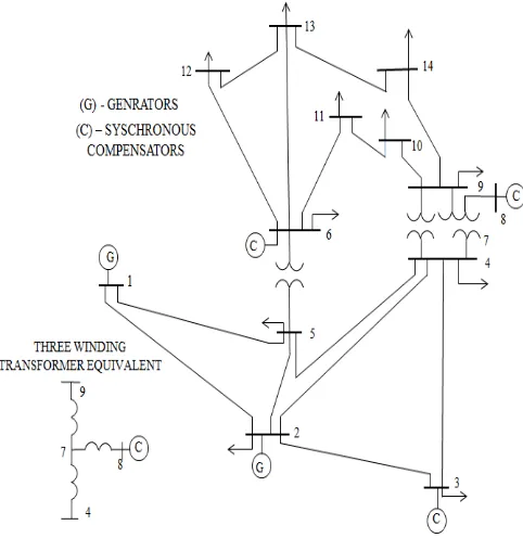
7. IEEE 14 BUS SYSTEM
The data of test system namely 14 Bus system is used. The single line diagram of the Standard IEEE 14 bus system is shown in fig. 5. The Standard IEEE 14 bus system has 14 loads fed by 9 generators.
Fig -5: IEEE – 14 Bus test system
The magnitude of voltage at bus 1 is conformed to 1.06 per unit. Line impedances are taken in per unit on a 100-MVA base. For standard IEEE 14 bus system the voltage compensation using UPFC system is also being studied. The impact of UPFC on system power flow has been fully tested on standard IEEE 14-bus.
8. BENEFITS AND COST OF UPFC
The benefits from the use of FACTS devices are many; however, not all are tangible. Similarly, the costs of FACTS devices are also huge. The cost has to compute against
anticipated benefits. One of the reasons for low deployment of FACTS is because very little has been done to show their profitableness. FACTS devices can save the system from potential threat of system collapse, which can have very serious consequences on other economic sector as well. It can help to avoid the wide spread blackout.
The opportunity cost of FACTS controllers in these situations has to take into consideration. As compared to conventional devices, FACTS controllers are very expensive. The total cost also depends on the size of fixed and controlled portion of the FACTS controller [13].
Facts devices
Power system stability enhance ment
Load flow
Voltage control
Transie nt stability
Dynamic stability
UPFC Yes High High Medium Medium
TCSC Yes Mediu
m
Low High Medium
SVC Yes Low High Low Medium
[image:5.595.41.282.344.592.2]SSSC Yes Low High Medium Medium
Table -1: Comparisons of Facts Controller
9. CONCLUSION
This paper presents a review of developed and under developing power electronics-based FACTS devices and their control features. Effectiveness of UPFC in controlling real and reactive power through the line.
The power flow and the voltage profile in various transmission lines along with and without the placement of UPFC in a specific transmission line is obtained in order to improve the system performance.
Hence the themes of the paper to maintain voltage stability have been successfully achieved with the incorporation of UPFC. For standard IEEE 14 bus system the voltage compensation using UPFC system is also being studied.
ACKNOWLEDGMENT
© 2017, IRJET | Impact Factor value: 5.181 | ISO 9001:2008 Certified Journal | Page 547
REFERENCES
[1] N. G. Hingorani and L. Gyugyi, “Understanding FACTS, Concepts, and Technology of Flexible AC Transmission Systems”, Piscataway, N IEEE Press, 2000.
[2] Satyavir Singh, Puneet Srivastava, “Implementation of Unified Power Flow Controller for Wheeling charges Reduction in a Deregulated Power System”, Ijetae, Vol. 2, Feb-2013.
[3] Raju Pandey And A. K. Kori August (2013) “Real And Reactive Power Flow Control Using Flexible Ac Transmission System Connected To A Transmission Line: A Power Injection Concept”, Volume 1, Issue 6, ISSN: 2278 – 1323 International Journal Of Advanced Research In Computer Engineering & Technology (IJARCET) Pp. 252 – 256.
[4] Mithu Sarkar, “Effect Of UPFC Allocation on Transmission System Power Loss”, Int.Conf. On Energy Efficient Technologies for System Sustainability (ICEETS-2013), IEEE, Tamilnadu, 10th – 12th April 2013.
[5] Gyugyi, L., Schauder, C.D., Williams, S.L., Reitman, T.R., Torgerson, D.R. and Edris, A. “The unified power flow controller: A new approach to power transmission control”, IEEE Transaction Power Delivery, Vol. 10, pp. 1085-1097, 1995.
[6] AmlanBarik, SidharthSabyasachi, “Control Design and Comparison of Unified Power Flow Controller for Various
Control Strategies” International Journal of Recent
Technology and Engineering (IJRTE) ISSN: 2277-3878, Volume-3, Issue-1, March 2014.
[7]Roopa. R, K.ShanmukhaSundar, “Enhancement Of System Performance Using Upfc”,Irf International Conference, 05th July-2014, Bengaluru, India, Isbn: 978-93-84209-33-9.
[8] Tanushree Kaul, Pawan Rana, “Modeling, Analysis and Optimal Location of UPFC for Real Power Loss Minimization”, International journal application, 7 July 2013.
[9]Sandeep Sharma and Shelly Vadhera, “Enhancement of Power Transfer Capability of Interconnected Power System Using Unified Power Flow Controller (UPFC)”, International Journal of Electronics and Electrical Engineering Vol. 4, No. 3, June 2016.
[10] A. Rajabi-Ghahnavieh, M. Fotuhi-Firuzabad, “UPFC for Enhancing Power System Reliability”, IEEE-2010.
[11] Kunal Gupta, Baseem Khan, “Available Transfer Capability Enhancement by Unified Power Flow Controller”, IEEE - 2015.
[12] Sadjad Galvani, MehrdadTarafdar Hagh, “Unified power flow controller impact on power system predictability”, IEEE-2014.
[13] Adit Pandita, Dr. Sanjay K. Jain, ”A Review on Power Flow Analysis with UPFC and its Applicability”, International Journal of Engineering Research & Technology (IJERT), Vol. 2 Issue 6, June – 2013.
![Fig.4 shows Single line diagram of UPFC and Phasor of voltage and current to V [17]. This gives a new line voltage V2 with different magnitude and phase shift](https://thumb-us.123doks.com/thumbv2/123dok_us/8165901.807229/3.595.40.284.445.714/single-diagram-phasor-voltage-current-voltage-different-magnitude.webp)