© 2017, IRJET | Impact Factor value: 5.181 | ISO 9001:2008 Certified Journal | Page 330
Cost Effective Ball Milling Machine for Producing Nanopowder
Shubham Krishna Mhetar
1, Akshay Ashok Nerle
2, Rohit Laxman Patil
3, Rahul Ankush Pawar
4Mayur Manik Patil
5Hemant Tanaji Shinde
612345
Mechanical Engineering Department, Sanjay Ghodawat institutes, Maharashtra, India.
6
Assistant Professor, Mechanical Engineering Department,
Sanjay Ghodawat institutes, Maharashtra, India.
---***---Abstract -
Research work related to metallurgy and mechanical department deals with the study of various ferrous and nonferrous materials. Usually properties of these materials enhance at microscopic level. These changes in properties have numerous applications. But in order to carry out research activities there must be ample supply of Nanopowder at low cost. Unfortunately this is not the case. The Nanopowder now obtained is produced through high energy planetary ball milling machine. The cost of this machine is high. Also the amount of powder produced is more .Our effort in this project is to minimize the production cost of Nanopowder by providing alternate machine. The major advantages of this machine include lower floor space, low initial cost. Also the quantity of nano powder required for testing is usually less. So the above mentioned machine can be used effectivelyKey Words: Ball milling, Cost effective, Nanopowder
1. INTRODUCTION
Nanotechnology is the science that deals with matter at the scale of 1 billionth of a meter (i.e., 10−9 m=1nm), and is also the study of manipulating matter at the atomic and Molecular scale. A nanoparticle is the most fundamental component in the fabrication of a nanostructure, and is far smaller than the world of everyday objects that are described by Newton’s laws of motion, but bigger than an atom or a simple molecule that are governed by quantum mechanics. In general, the size of a nanoparticle spans the range between 1 and 100 nm.
There are several Synthesis methods for creating nanoparticles like, Physical vapor deposition, Chemical vapor deposition, Sol-gel Method, RF Plasma Method, Pulsed Laser Method, Thermolysis and Solution Combustion Method. But these methods are Very costly, so comparatively cheaper method has to be developed.
Synthesis of nanomaterials by a simple, low cost and in high yield has been a great challenge since the very early development of nanoscience. Various different processes have been developed for the commercial production of nanomaterials. Among all top down approaches, high energy
ball milling, has been widely exploited for the synthesis of various nanomaterials.
Various types of high-energy milling equipment are used to produce nanopowder. They differ in their capacity, efficiency of milling and additional arrangements for cooling, heating, etc. 1. SPEX shaker mills 2. Planetary ball mills 3. Attritor mills. These methods although cheaper than the chemical method but still are very high priced. Hence in this project we have developed a machine which will manufacture nanopowder cheaper than the above mentioned methods. A principle of high-energy ball milling is used in order to produce nanopowder. Our project is beneficial to most of the educational institutions to carry out research work related to nanotechnology. It is a simple process and does not include working with hazardous chemicals.
2. DESIGN
I. DESIGN
Shaft Design:
Motor used = 1HP
So Power P = (kw) = 0.735 KW, Speed (N) =750rpm.
Tension on tight side and slack side of the belt:
V = =1.57m/s. D =Diameter of Pulley.
So power (P) = (T1-T2) V
735 = (T1-T2) × 1.57
T1 –T2 =468 N
Angle of Wrap θ = π - 2sin-1 ) = 3.02 radians
We know that,
= = e (0. 27×3 .02)
T1 = 2.26 T2
© 2017, IRJET | Impact Factor value: 5.181 | ISO 9001:2008 Certified Journal | Page 331
T2 = 371.42 = 371 N. T1 = 839 N = 840 N
Weight of pulley W = 0.75 × 9.81 = 7.5 N.
Torque available on shaft,
Mt = N = minimum Speed available on shaft.
Mt = = 35093.66 Nmm.
60 500
(T1+ T2 B
Downward Force = T1 + T 2=1310N.
So Moment @ C = RB × 500 – 1310 ×500 Nmm
RB = 1467.2 N
Moment @ B = (1310) × 60 = 78600 Nmm
Failure criteria for shaft (Torsional & Bending)
=
=
C =
d = 19.05 mm, so d = 20 mm.
Voil Design
From design data book / metallurgy book
Density of graphite power: 2160 kg/m3
Density of strain hardening steel ball = 7850 kg/m3
The voil is designed for milling of 250 gm. of graphite material
So, Mass of the graphite material = 250 gm.
So we know that,
Mass (m) = density ( × volume
So V = = = 1.1574 × 10⁻⁴ m3
Volume of Graphite material (Vg) = 1.1574 × 10⁻⁴ m3
(ii) Mass of the ball = 10 times of the graphite material
So (M)b = 10×( M)g =10×250= 2500 gram = 2.5 kg
So volume of ball = = = 3.1847×10⁻⁴m3
(iii) Volume of the blade, (V) blade= l× b× h
(V) Blade = (0.03) × (0.005) (0.01) ×4= 6×10 -6
m3
(iv)Volume of shaft, (V) s = ×d2× (1.25d)
= × (0.02)2× (1.25×0.02) = 7.8539×10⁻⁶ m3
(V)Material = (V) g+ (V) b+ (V) Blade
=1.1574×10⁻⁴+3.1847×10⁻⁴+6×10-6
= 4.4021×10⁻⁴m3
Now, (Free Space = 2 × (V) Material)
Total Volume = 2 × (V) Material
= 2×4.4021×10-4= 8.0842×10⁻⁴ m3
Volume of Voil = Total Volume + Shaft Volume
= 8.0842×10⁻⁴ + 7.8539×10-6
= 8.1627×10⁻⁴ m3
Volume of Voil = × (Di)
2
×(1.25Di)
8.1627×10-4 = ×1.25×Di
3
Di 3
= 8.3144×10⁻⁴ mm3
Di = 0.09403 m Di = 94.03 mm = 100 mm
So, Internal Diameter of Voil = 100 mm
Thickness of Voil = 10 mm Outer Dia. Of Voil = 120 mm.
Bearing Design
Selection of Bearing at Shaft,
Radial Force (Fr) = 1310 N Axial Force (Fa) = 705 N
Speed =750 RPM/ Bearing Life = 12000 Hrs.
Diameter of Shaft (d) = 20 mm.
So, = = 6.19×10⁻³< e
© 2017, IRJET | Impact Factor value: 5.181 | ISO 9001:2008 Certified Journal | Page 332
So Equivalent Dynamic Load (P) = XFr+ YFa
P=XFa P = 1310 N
Rated Bearing Life (L10) =
= = 54 Million Revolutions
Now, Dynamic Load Capacity,
C = P(L10) = 4573.51 N
From Table (V.B Bhandari)
For Diameter (d) = 20 mm
Bearing = 16404 (L= 7020 N)
d = 20 mm D = 40 mm B = 8 mm.
3. CONSTRUCTION
For our experiment, we used EN8 (Carbon 0.36-0.44%, Silicon 0.10-0.40%, Manganese 0.60-1.00%, Sulphur 0.050 Max, Phosphorus 0.050%) as our grinding media and grinding jar. For the jar, inner diameter of 100 mm and thickness of 10 mm is chosen as our design. The jar has approximately 8.1627×10⁻⁴ m3 of volume and it can withstand
4.4021×10⁻⁴m3 of grinding media. The voil (grinding jar) cap
[image:3.595.308.560.120.285.2]has an arrangement that clamps itself with voil. The voil cap has an opening for the shaft. The shaft of diameter 25.4 mm is inserted through this opening. The blades are attached to the shaft with the help of grab screw. For grinding media, 5mm and 10mm diameter of stainless steel balls are used. For our shafts, we used the mild steel provided in store and went to labs for machining purpose.
Fig no 1: Voil
There are three shafts in our system- main shaft and speed reduction gearbox shaft. The head of speed reduction gearbox shaft is reduced to 14mm diameter using lathe machine to fit in the pulley which has 16mm hole at middle. For the body of shaft, we reduced it into 20mm diameter.
[image:3.595.372.495.371.599.2]The shaft has two universal joints to compensate for the angular movement when the shaft swivels.
Fig no. 2: Main Shaft
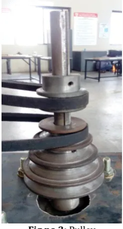
[image:3.595.36.289.554.711.2]The upper side of the shaft is connected to the pedestal bearing. Due to the bearings have hole of 17mm; we make a small portion of 16.9- 16.95mm on shaft to fit in the bearing since the bearing has small tolerance. Four speed pulley is attached at one end of the shaft. The other pulley is mounted on the motor shaft. A V-belt is provided which takes care of power transmission.
Fig no 3: Pulley
© 2017, IRJET | Impact Factor value: 5.181 | ISO 9001:2008 Certified Journal | Page 333 about 60 mm motor drives another pulley. This pulley is
[image:4.595.39.285.135.294.2]directly connected to the shaft of speed reduction gearbox. The speed reduction gearbox has the reduction ratio of 15:1.
Fig no 4: Voil Handle
[image:4.595.47.558.433.771.2]The drive from the speed reduction gearbox is given to the voil through rack and pinion. The rack and pinion is used to provide to and fro motion to the voil. The rack is placed on the voil handle. The voil handle is designed for easy removal of voil whenever required. Bearing are provided at each side for proper functioning. These bearings are attached to main frame which is made up of M.S square bar 1.5*1.5 inches in cross section.
Fig no 5: Machine
4 WORKING
The three phase A.C supply is given to the motor. The motor has power of 1 Hp. The motor is clamped vertically to the frame using bolts. The shaft of motor has two pulleys. viz, four speed pulley and single speed pulley. The power is transmitted from four speeds from four speed pulley to the main shaft. The main shaft which has two universal joints is fixed with the help of bearings. The maximum speed achieved in this case is 690 rpm. This shaft has four blades attached to its end using grab screw. The shaft is then placed inside the voil. Suitable amount of ball bearings are placed inside the voil. During the actual operation, due to high speed ball milling principle actual powder is formed. Suitable time gaps are provided so that the powder does not adhere to the face of voil.
This is intermittent process and takes about 3-4 hours as per the volume of solid to be powdered. The voil has a separate clamping mechanism. The voil is held in the voil handle. The voil is handle is designed for easy removal of voil whenever required. The voil handle moves to and fro by rack and pinion mechanism. This mechanism is attached to the separate frame which is welded to base. The rack slides up and down through a plate which is attached to the speed reduction gearbox shaft. The power input from the motor is given to the speed reduction gearbox through pulley
[image:4.595.302.562.454.705.2]5 RESULTS
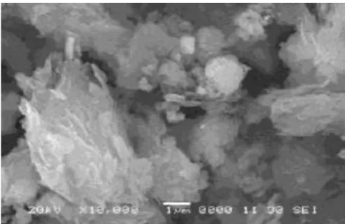
© 2017, IRJET | Impact Factor value: 5.181 | ISO 9001:2008 Certified Journal | Page 334 Fig no 7: SEM image of graphite after 200 min milling with
SS balls
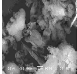
The powder obtained from the machine was tested on scanning electron microscope (SEM). Figure 6 shows image of graphite after 100 min milling with SS balls and Figure 7 shows image of graphite after 100 min milling with SS balls. When tested their size was within the range of nanoparticles. Thus it can be concluded that this machine can produce nanopowder effectively.
REFERENCES
[1] C. Suryanarayana, ‘Mechanical alloying and milling’,
Department of metallurgical and Materials Engineering, Colorado School of Mines, Golden, CO 80401-1887, USA.
[2] Thakur Prasad Yadav, Ram Manohar Yadav and Dinesh
Pratap Singh, ‘Mechanical Milling: a Top down Approach
for the Synthesis of Nanomaterials and
Nanocomposites’, Department of Physics, the University of Liverpool, Liverpool.
[3] VJ Mohan raj and Y Chen, ‘Nanoparticles – A Review,
Orchid Chemicals & Pharmaceuticals Limited, Chennai, India School of Pharmacy, Curtin University of Technology, Perth, Australia.
[4] Design and Fabrication of Mini ball mill. Rutheravan Maria
Automotive Engineering Research Group (AERG), Faculty of Mechanical Engineering, Universiti Malaysia Pahang (UMP), 26600 Pekan, Pahang, Malaysia,
[5] Design Method of Ball Mill by Discrete Element Method.
[image:5.595.36.289.97.259.2]