© 2018, IRJET | Impact Factor value: 6.171 | ISO 9001:2008 Certified Journal | Page 2782
PERFORMANCE ANALYSIS OF PHASED ARRAY, MIMO AND PHASED
-MIMO RADARS
A. MAHESH BABU
1, CH. PAVAN KUMAR
2, A. SRILEKHA
3,
B. SWATHI
4, T. JYOSHNA
5,
U. TEJOKUMARI
61Assistant Professor of Electronics and Communication Engineering Gayatri Vidya Parishad College for Degree and PG Courses School of Engineering, Visakhapatnam, Andhra Pradesh, India.
2,3,4,5,6Students of Department of Electronics and Communication Engineering Gayatri Vidya Parishad College for Degree and PG Courses School of Engineering, Visakhapatnam, Andhra Pradesh, India.
---***---Abstract - We introduce a new technique for multiple-input multiple-output (MIMO) radar with closely spaced antennas which we call phased-MIMO radar. The new technique enjoys the advantages of the MIMO radar without losing the main advantage of the phased-array radar, that is scanning the targets almost instantaneously by using electronic switching for beam steering at the transmitting side. The theme of the proposed technique is to partition the transmit array into sub-arrays that are allowed to overlap. Then, each sub-array is used to transmit a waveform which is orthogonal to the waveforms transmitted by other arrays. Also, the sub-arrays are combined jointly to form a MIMO radar resulting in higher angular resolution capabilities. The improvements offered by the phased-MIMO radar technique when compared to the phased-array and MIMO radar techniques are demonstrated mathematically and by simulations through analyzing the respective beam-patterns and the output signal-to- noise-plus- interference ratios. These results show that the proposed phased-MIMO radar is better when compared to MIMO and phased-MIMO radars.
Key Words:MIMO, phased array radar, beam-forming, phased MIMO radar, waveform diversity.
1. INTRODUCTION
Radar was initially designed for defense applications. Due to the applicability of radars for a variety of uses ranging from micro-scale radars applied in biomedical engineering to macro-scale radars used in radio-astronomy the quest for new radar techniques has begun. To date, previous developments in radar were based on the idea that the target can be tracked instantaneously by using electronic beam steering. The corresponding radar technique is well known as phased-array radar.
In the last decade, the development of a new radar technique that is best known as multiple-input multiple-output (MIMO) radar has become the focus of intensive research. The concept of the MIMO radar is to employ multiple antennas for emitting several orthogonal waveforms and multiple antennas for receiving the echoes reflected by the target. The concept of transmission of multiple orthogonal waveforms from different antenna’s, is usually termed as the waveform diversity.
Recently, some attempts to exploit jointly the benefits of the phased-array and MIMO radars have been also reported. In [4], a general antenna configuration is considered where several well - separated sub-arrays are used to form a MIMO radar with each sub-array operating in phased-array mode. In [5], the idea of dividing the aperture of the transmit array with co-located antennas into multiple disjoint sub apertures has been introduced. Utilizing the same partitioning structure, the authors of [6]–[8] have developed closed-form expressions for MIMO signal sets to achieve wide transmit beam-pattern.
In this paper, we consider a radar system with co-located antennas and introduce transmit array partitioning to integrate the phased-array radar into the MIMO radar. Indeed, as compared to the phased-array radar, the use of MIMO radar with co-located antennas enables improving angular resolution, increasing the number of detectable targets, improves parameter identification, extending the array aperture by virtual sensors, and enhancing the flexibility for transmit/receive beam-pattern design. The MIMO radar with co-located antennas may suffer from beam-shape loss which leads to performance degradation. Moreover, the MIMO radar exhibits loss in the signal-to-noise ratio (SNR) gain.
To overcome these demerits of the MIMO radar, we develop a new radar technique which combines the advantages of the MIMO radar (such as waveform diversity) with the advantages of the phased-array radar (such as Beam steering). In order to enable this possibility, we partition the transmit array into a number of sub-arrays that are allowed to overlap. Then, each sub-array is used to transmit a waveform which is orthogonal to the waveforms transmitted by other sub-arrays. In parallel, the sub-arrays are combined jointly to form a MIMO radar resulting in higher angular resolution capabilities.
© 2018, IRJET | Impact Factor value: 6.171 | ISO 9001:2008 Certified Journal | Page 2783
Particularly, the new radar technique:
i) Enjoys all the advantages of the MIMO radar, i.e., it enables improving angular resolution, detecting a higher number of targets, improving parameter identification, and extending the array aperture;
ii) Enables the use of existing beam-forming techniques at both the transmitting and the receiving ends;
iii) Provides the means for designing the overall beam-pattern of the virtual array;
iv) Offers a tradeoff between angular resolution and robustness against beam-shape loss;
v) Offers improved robustness against strong interference. The simulations are based on the analysis of the phased-MIMO radar with transmit/receive beam-forming. Particularly, we derive the phased-MIMO radar beam-pattern for the case when conventional transmit/receive forming is used, and compare it with the beam-patterns of the phased-array and MIMO radars.
Also we compare the above mentioned radar techniques in terms of their achievable output SINRs. The possibility of using robust/adaptive beam-forming is also discussed.
2. PHASED-MIMO RADAR
The main idea behind our formulations is to partition the transmit array into ‘K’ sub-arrays (1 <= K <= M) which are allowed to overlap. In general, each transmit sub-array can be composed of any number of antennas ranging from 1 to M such that no array is exactly the same as another sub-array, with each sub-array consisting of M-K+1 array elements.
3. SIMULATIONS
In our simulations, we consider a uniform array of M=10 omnidirectional antennas used for transmitting the baseband waveforms, and N=10 omnidirectional antennas spaced half a wavelength apart from each other at the receiving end.
In all our simulation examples we compare our phased-MIMO radar with the phased-array radar and the phased-MIMO radar. For the phased-MIMO radar, we always used K=5 sub-arrays which are assumed to be fully overlapped.
3.1. Non-adaptive Transmit/Receive Beam-forming
Example-1: Non-adaptive Transmit/Receive Beam-pattern Without Spatial Transmit Aliasing: In the first example, we examine the transmit/receive beam-pattern of the transmit/receive beam-former, for the case when the transmit antennas are located half a wavelength apart,
i.e., = 0.5 wavelength. Figs.1 and 2 show the transmit
beam-patterns and the waveform diversity beam-patterns,
[image:2.595.326.537.126.291.2]respectively, for all three radar techniques tested, while Fig. 3 shows the overall transmit/receive beam-patterns for the same techniques.
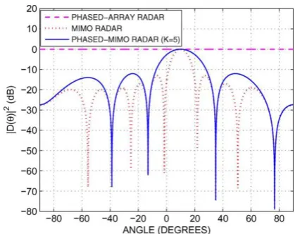
Fig-1.First example: transmit beam-patterns using
conventional beam-former ( =0.5 wavelength).
From Fig. 1, we can see that the phased-array radar has the typical conventional beam-pattern with main-lobe centered
at
θ
s while the MIMO radar has flat (0 dB) transmitting gain.On the other hand, the phased-MIMO transmit beam-pattern is characterized by the aperture (actual size) of the individual sub-arrays. Since the aperture of the sub-arrays is always smaller than the aperture of the whole array, the transmit beam-pattern of the phased-MIMO radar represents a tradeoff between the beam-patterns of the MIMO and phased-array radars. As we can see in Fig. 1, the reduction in the sub-array aperture results in the beam-pattern of the phased-MIMO radar with a wider main beam and a little higher side-lobe levels as compared to the beam-pattern of the phased-array radar. This small loss in beam-pattern shape is repaid at a greater gain in the waveform diversity beam-pattern as shown in Fig. 2.
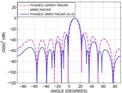
Fig-2.First example: waveform diversity beam-patterns
[image:2.595.328.538.546.712.2]© 2018, IRJET | Impact Factor value: 6.171 | ISO 9001:2008 Certified Journal | Page 2784
It is noted from Fig.2 that the phased-array radar has no waveform diversity gain (0 dB flat pattern), while the waveform diversity beam-patterns of the MIMO and phased-MIMO radars are equivalent to conventional beam-patterns offered by an M and K elements virtual arrays, respectively.
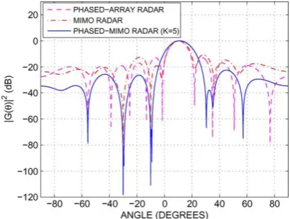
Fig-3.First example: overall beam-patterns using
conventional transmit/receive beam-former ( = 0.5
wavelength).
However, one can see in Fig.3 that the overall transmit/receive beam-pattern shape for the proposed phased-MIMO radar is significantly improved as compared to the beam-patterns of the phased-array and MIMO radars.
Example-2: Non-adaptive Transmit/Receive Beam-pattern With Spatial Transmit Aliasing: In this example, we investigate the non-adaptive transmit/receive beam-pattern for the case when the transmit antennas are located more than a half wavelength apart from each other. In
particular, the case =2.5 is chosen and the corresponding
non-adaptive beam-forming based beam-patterns for the phased-array, MIMO, and phased-MIMO radars are plotted. In this case, the transmit beam-patterns for all aforementioned techniques have similar trends to their counterparts in Fig. 1 except that, due to spatial aliasing in the transmit mode, each beam-pattern is repeated five times within the spatial domain. The reason is that the inter-element spacing is five times half a wavelength, i.e., five times the critical spatial sampling spacing. Similarly, the diversity beam-patterns also exhibit spatial aliasing for all the techniques tested. The overall transmit/receive beam-pattern is shown in Fig. 4.
Fig-4.Second example: overall beam-patterns using
conventional transmit/receive beam-former ( =2.5
wavelength).
It can be seen from this figure that the phased-array and MIMO radars have exactly the same transmit/receive patterns, while the proposed phased-MIMO radar beam-pattern enjoys much lower side-lobe levels as compared to the beam-patterns of the other radar techniques. Hence, the proposed phased-MIMO radar is shown to offer a much better overall performance.
Example-3:Non-adaptive Output SINR: In this example, the non-adaptive beam-former output SINR is tested versus SNR for different INR values. Fig.5 shows the output SINR versus SNR for the phased-array, MIMO, and phased-MIMO radars.
Fig-5.Third example: non-adaptive transmit/receive output SINRs versus SNR at fixed INR= 30 dB
[image:3.595.324.550.67.246.2] [image:3.595.58.266.150.309.2] [image:3.595.327.539.478.642.2]© 2018, IRJET | Impact Factor value: 6.171 | ISO 9001:2008 Certified Journal | Page 2785
compared to both the phased-array and MIMO radars. Fig. 6 shows the output SINR versus SNR while the INR is fixed to 30 dB
Fig-6.Third example: non-adaptive transmit/receive output SINRs versus SNR at fixed INR= -30 dB
It can be seen from the figure that the phased-array radar output SINR is ten times higher than the MIMO radar output SINR.
Example-4: Non-adaptive Output SINR in the Presence of Spatially Distributed Interference: In this example, we assume one spatially distributed interference source which is uniformly spread over the spatial sector. Fig.7 shows the
output SINR versus SNR where the INR is varied.
Fig-7.Fourth example: non-adaptive transmit/receive output SINRs versus INR = SNR; spatially distributed
interference.
It can be seen from the figure that at low SNR the phased-array radar output SINR is higher than the MIMO radar output SINR. At low SNR values, the output SINR of the phased-MIMO radar is comparable to the output SINR of the phased-array radar which coincides with our theoretical founding.
3.2. Adaptive Transmit/Receive Beam-forming
Example 5: MVDR Beam-forming Employing Multiple Transmit Multiple Receive Antenna’s: In this example, the MVDR receive beam-forming is used for the phased-array, MIMO, and phased-MIMO radars. All simulation parameters are the same as in Example 1.The receive MVDR beam-pattern is shown in Fig.8 for all radar techniques tested.
Fig-8.Fifth example: overall beam-patterns using MVDR
beam-former ( =0.5 wavelength).
It can be observed from this figure that all radar techniques exhibit nulls at the locations of the powerful interference. This means that the phased-MIMO radar has almost the same robustness against sensor noise as the phased-array radar. At the same time, it enjoys the advantages of the MIMO radar, e.g., waveform diversity.
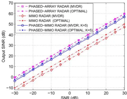
Fig.9 shows the optimal SINR as well as the MVDR output SINR versus SNR (INR is fixed to 30 dB) for all radar techniques tested.
[image:4.595.58.266.128.289.2] [image:4.595.326.538.186.347.2] [image:4.595.59.266.456.620.2] [image:4.595.326.539.529.695.2]© 2018, IRJET | Impact Factor value: 6.171 | ISO 9001:2008 Certified Journal | Page 2786
From this figure, we can see that the phased-MIMO radar exhibits SINR performance that is very close to the phased-array SINR performance.
[image:5.595.59.264.209.364.2]Example 6: MVDR Beam-forming Employing Multiple Transmit Single Receive Antenna’s: The same scenario as in Example 5 is considered here except that the number of receive antennas is N=1.The MVDR beam-former is used for the MIMO and phased-MIMO radar techniques and the MVDR beam-patterns are plotted in Fig. 10 for INR=50 dB
Fig-10.Sixth example: overall beam-patterns using MVDR beam-former, N=1 receive antenna.
[image:5.595.59.265.507.666.2]Fig.10 demonstrates that the proposed phased-MIMO radar enjoys the advantages of phased-array and MIMO radars and, therefore, is superior to both.
Fig.11 shows the optimal SINRs as well as the MVDR output SINRs versus SNR (INR is fixed to 30 dB) for all radar techniques tested.
Fig-11.Sixth example: output SINRs versus SNR, N=1 receive antenna.
The phased-MIMO radar exhibits the SINR performance that is superior to the performance of both the phased-array and MIMO radars. This gain is attributed to the ability of the
phased-MIMO radar to reject interference combined with its robustness against sensor noise.
4. CONCLUSION
This newly proposed technique for MIMO is based on partitioning the transmit array to a number of sub-arrays which are allowed to overlap. Each sub-array is used to transmit a waveform which is orthogonal to the waveforms transmitted by other sub-arrays. The sub-arrays are combined jointly to form a MIMO radar resulting in higher angular resolution capabilities. It is shown that the proposed technique has the advantages of both phased-array and MIMO radars and, therefore, it has a superior performance. Simulation results confirm our theoretical observations and demonstrate the effectiveness of the proposed phased-MIMO radar technique. This new phased-MIMO radar technique paves way for developments in MIMO radar. Some new problems highlighted in the paper are the transmit beam-forming and transmit sub-array waveform designs, which satisfy certain desired properties.
ACKNOWLEDGEMENT
This research was supported by Mr. A. Mahesh Babu, Asst. Prof., B. Tech., M. Tech. We thank our sir, friends from Gayatri Vidya Parishad College for Degree and PG Courses School Of Engineering who provided insight and expertise towards Phased MIMO radar which combine’s the merits of both phased and MIMO radars. We would also like to thank all others who helped us in doing this project.
REFERENCES
[1] M. I. Skolnik, Introduction to Radar Systems, 3rd ed.
New York: Mc-Graw-Hill, 2001.
[2] I. Immoreev and T.-H. Tao, “UWB radar for patient
monitoring,” IEEE Aerosp. Electron. Syst. Mag., vol. 23, pp. 11–18, Nov. 2008.
[3] E. Fishler, A. Haimovich, R. Blum, D. Chizhik, L. Cimini,
and R.Valenzuela, “MIMO radar: An idea whose time has come,” in Proc.IEEE Radar Conf., Honolulu, HI, Apr. 2004, vol. 2, pp. 71–78
[4] L. Xu and J. Li, “Iterative generalized-likelihood ratio test
for MIMO radar,” IEEE Trans. Signal Process., vol. 55, no. 6, pp. 2375–2385, Jun. 2007.
[5] J. Bergin, S. McNeil, L. Fomundam, and P. Zulch, “MIMO
phased-array for SMTI radar,” in Proc. IEEE Aerospace Conf., Big Sky, MT, Mar. 2008, pp. 1–7.
[6] J. P. Browning, D. R. Fuhrmann, and M. Rangaswamy, “A
© 2018, IRJET | Impact Factor value: 6.171 | ISO 9001:2008 Certified Journal | Page 2787
Processing Signal Processing Education Workshop (DSP/SPE), Marco Island, FL, Jan. 2009, pp. 446–450.
[7] D. Fuhrmann, P. Browning, and M. Rangaswamy,
“Constant-modulus partially correlated signal design for uniform linear and rectangular MIMO radar arrays,” in Proc. 4th Int. Conf. Waveform Diversity Design (WDD), Orlando, FL, Feb. 2009, pp. 197–201.
[8] D. Fuhrmann, P. Browning, and M. Rangaswamy,
“Signaling strategies for the hybrid MIMO phased-array radar,” IEEE J. Sel. Topics Signal Process., vol. 4, no. 1, pp. 66–78, Feb. 2010.
[9] A. Hassanien and S. A. Vorobyov, “Direction finding for
MIMO radar with colocated antennas using transmit beamspace preprocessing,” in Proc. IEEE Int. Workshop Comp. Advanc. in Multi-Sensor Adapt. Process. (CAMSAP’09), Dutch Antilles, Aruba, Dec. 2009, pp. 181– 184.
[10] J. Li and P. Stoica, “MIMO radar with colocated
antennas,” IEEE Signal Process. Mag., vol. 24, pp. 106– 114, Sep. 2007.
[11] A. Hassanien, S. A. Vorobyov, and K. M. Wong, “Robust
adaptive beamforming using sequential programming: An iterative solution to the mismatch problem,” IEEE Signal Process. Lett., vol. 15, pp.733–736, 2008.
[12] D. Fuhrmann and G. Antonio, “Transmit beamforming
for MIMO radar systems using signal cross-correlation,” IEEE Trans. Aerosp. Electron. Syst., vol. 44, pp. 171–186, Jan. 2008.
[13] A. Maio and M. Lops, “Design principles of MIMO radar
detectors,” IEEE Trans. Aerosp. Electron. Syst., vol. 43, pp. 886–898, Jul. 2007.
[14] S. M. Alamouti, “A simple transmitter diversity scheme
for wireless communications,” IEEE J. Sel. Areas Commun., vol. 16, pp. 1451–1458, Oct. 1998.
[15] D. Tse and P.Viswanath, Fundamentals of Wireless