Effect of Enlargement of Joint on the Performance of Interior and
Corner Beam-Column Joint
Anoop Krishnan K M
1, Rona Maria P James
21
PG Student, Dept. of Civil Engineering, Vimal Jyothi Engineering College, Chemperi, Kannur, Kerala
2Asst.Prof. Dept. Of Civil Engineering, Vimal Jyothi Engineering College, Chemperi, Kannur, Kerala
---***---Abstract
While constructing a structures in an earthquakeprone area, there needs additional design procedures to withstand the effect that comes due to the earthquake. The main part of the bulling that affects badly is the joint portion which needs proper design. The joint are becomes structurally unstable when lateral loads like earthquake loads act on them. Transverse hoops are incorporated in high percentage to withstand the impact of lateral loads. Joint enlargement gives many advantages over other common methods. It becomes economical since conventional materials likes concrete and steel is used for the purpose of joint strengthening. The enlargement can be given to interior joint, exterior joint or corner joint.
Key Words:
Beam-column joint, RCC, Joint
enlargement, ANSYS, FEM
1. INTRODUCTION
There were many devastation and destruction of structures due to joint failures during earthquakes. If joints are not properly designed and detailed, it can damage the entire structure. Beam-column connections have been identified as potentially one of the weaker components Numerous researches were carried out on different retrofit techniques including the use of concrete jackets, bolted steel plates, and FRP sheets, which were considered in the structural upgrading, especially for columns and beam–column joints in the moment-resisting frames. Among these retrofit techniques, RC jacketing is widely used because it is more consistent with as-built RC structures than the other retrofit materials, such as steel or FRP jacketing, and the deficient beam– column joints can be easily repaired.
2. MODELING
2.1 General
ANSYS is a finite element analysis tool for structural analysis and explicit studies. ANSYS offers an easy and flexible platform for performing analysis of structures or models with great accuracy. ANSYS consists of two working platforms called APDL and workbench among which workbench provides more automated options for the analysis operations.
This is usually done using numerical approximation in structural analysis is the Finite Element Method
2.2 Details of specimen
The beams are 150mm deep by 100 mm wide and columns are 150 mm deep by 100 mm wide. The M30 grade concrete and Fe 415 grade steel were used. Steel bars of yield stress 415N/mm2 were used as main reinforcement and stirrup..
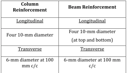
[image:1.595.306.562.326.474.2]Table -1: Reinforcement details
Table -2: Properties of the Specimen
Material
model No. Element type properties Material
1 Reinforcement
Linear Isotropic Elastic Modulus 2.0× N/mm2 Poisson’s Ratio 0.3
2 Concrete
Linear Isotropic Elastic Modulus 27386.12 N/mm2 Poisson’s Ratio
0.15
Modeling of the corner and interior beam-column joints without joint enlargement is done. The specimen was given to cyclic load for a fixed deformation of 5mm all are done in ANSYS Workbench 16.1
Column
Reinforcement Beam Reinforcement
Longitudinal Longitudinal
Four 10-mm diameter Four 10-mm diameter (at top and bottom)
Transverse Transverse
6-mm diameter at 100
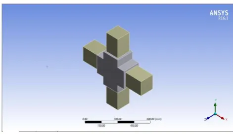
2.3 Modeling
[image:2.595.312.556.213.349.2]Fig -1 Corner joint without enlargement
[image:2.595.35.287.288.421.2]Fig -2 Corner joint with enlargement
Fig -3Interior joint without enlargement
3. ANALYSIS
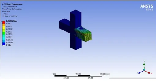
The analysis of the corner beam column joint of given dimensions, is done using the ANSYS software and the details are given. Cyclic loading is done to any of the beams, for a fixed deformation rate.
[image:2.595.314.555.383.513.2]The following figures show the result of the analysis on the corner beam column joint without enlargement that is given cyclic loading.
Fig -5 Load in corner joint without enlargement
Fig -6 Stress in corner joint without enlargement
[image:2.595.44.278.459.587.2] [image:2.595.314.555.542.679.2] [image:2.595.42.278.619.755.2]Fig -8 Application of load in corner joint with enlargement
Fig -9 Stress in corner joint with enlargement
Fig -10 Deformation in corner joint with enlargement
[image:3.595.310.563.270.407.2]The interior beam column joint without enlargement is then given the cyclic loading for a fixed deformation rate.
Fig -11 Load in interior joint without enlargement
Fig -12 Stress in interior joint without enlargement
Fig -13 Deformation in interior joint without enlargement
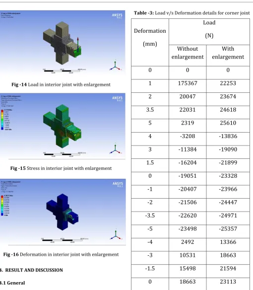
[image:3.595.37.288.438.579.2] [image:3.595.308.563.445.578.2]Fig -14 Load in interior joint with enlargement
[image:4.595.38.549.79.664.2]Fig -15 Stress in interior joint with enlargement
Fig -16 Deformation in interior joint with enlargement
4. RESULT AND DISCUSSION
4.1 General
The beam-column joints were analysed in ANSYS workbench 16.1. The deformations values, load-deformation relations and the capacity to withstand the load, of each specimen are included in the results
Table -3: Load v/s Deformation details for corner joint
Deformation
(mm)
Load
(N)
Without
enlargement
With
enlargement
0
0
0
1
175367
22253
2
20047
23674
3.5
22031
24618
5
2319
25610
4
-3208
-13836
3
-11384
-19090
1.5
-16204
-21899
0
-19051
-23328
-1
-20407
-23966
-2
-21506
-24447
-3.5
-22620
-24971
-5
-23498
-25357
-4
2492
13366
-3
10531
18663
-1.5
15498
21594
0
18663
23113
Table -4: Load v/s Deformation details for interior joint.
Deformation
(mm)
Load
(N)
Without
enlargement
With
enlargement
0
0
0
1
21787
26508
2
23819
27906
3
25317
28644
4.5
26818
29490
5
27137
29736
4
-5711
-18702
3
-14126
-23495
2
-18438
-25355
1.25
-20504
-26212
0.5
-21950
-26844
0
-22740
-27234
-0.5
-23435
-27577
-1
-24068
-27893
-1.75
-24819
-28340
-2.875
-25815
-28932
-4.5625
-27064
-29705
-5
-27361
-29898
-4.5
-2283.3
11552
-4
-67212
18549
-3.5
6279
21676
-2.75
1510
23964
-2
18123
25194
-0.875
21014
26361
0
22495
27092
The maximum load that the interior joint without enlargement can withstand is found to be 27.1kN and for the interior joint with enlargement is found 30kN. The maximum stress acting on the interior joint without enlargement is obtained as 7.68MPa and that of with enlargement is 6.51MPa. There is reduction in the stress about 15.2% when the joint is enlarged.
Chart -1 : Comparison of Load-Deformation variation for corner joint with and without enlargement
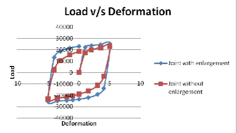
Chart -2 : Comparison of Load-Deformation variation for interior joint with and without enlargement
enlargement; shows that the capacity of the joint is increased as the joint portion is enlarged. The maximum load that the joint without enlargement is found to be 27.1kN; and that of interior joint with enlargement is 30kN The increment in the load capacity is the result of enlargement of the beam column joint. This shows that there is increment in strength when the joint portion is enlarged.
Table -5: Result of the Analysis
Corner joint Interior joint
Without enlarge ment With enlargem ent Without enlargem ent With enlargem ent Load
(kN) 23.2 25.2 27.1 30
Stress
(MPa) 7.38 6.91 7.68 6.51
4.3 Discussion
It is found that the maximum load that can be carried by the joint is increased when the joint is enlarged For corner joint, the capacity of joint without
enlargement is 23.2kN and for the joint with enlargement is 25.2kN
For interior joint, the capacity of joint without enlargement is 27.1 kN and for the joint with enlargement is 30kN
Total stress at joint decreases as the joint is enlarged. For corner joint, stress reduces from 7.38MPa to
6.91MPa
For the interior joint, stress reduces from 7.68MPa to 6.51MPa
3. CONCLUSIONS
Many parameters affect the design of joint enlargement, for example, the size, reinforcement and material strengths of beam, column and joint panels. The joint region was enlarged 20mm than the control specimen. The results yield the following conclusions.
1) The corner joint with enlargement can withstand 10
3) The interior joint with enlargement can withstand 12 % more load than that in joint without enlargement
4) There is reduction in the stress about 15.2 % when the joint is enlarged. It is obtained that when the joint region is enlarged; stress in the joint has reduced
REFERENCES
[1] Khair Al-Deen Bsisu , Belal O. Hiari, 2011, “Finite Element Analysis of Retrofitting Techniques for Reinforced Concrete Beam-Column Joint”, 8, 48-56 [2] S. Rajagopal, S. Prabhavathy ,2014, “Study on Exterior
RC Beam-Column Joints Upgrade with SIFCON in Joint Core Under Reversed Cyclic Loading”, 2, 183-194 [3] K.R. Bindhu, P.M. Sukumar , K.P. Jaya, 2009,
“Performance of Exterior Beam-Column joints under Seismic type Loading”, 2, 47-63
[4] Amorn Pimanmans, Preeda Chaimahawan, 2010, “Shear Strength of Beam-Column Joint with Enlarged Joint Area”, 32, 2530-2542