-GenRad Corp. future data PROGRAMMING THE AMDS
future~
MICROCOMPUTER
,
PROGRAMMING THE AMDS
GenRad FUTUREDATA COMPUTER CORPORATION 5730 BUCKINGHAM PARK WAY
This manual provides information on the AMOS memory structure, utility subroutines, and direct I/O programming, and is organized in three sections as follows:
1) "Debugger Memory Usage" describes memory configuration and the essentials of Debugger operation.
2) "I/O Service Subroutines" explains the calling conventions
and operation of the system I/O routines contained on the AMOS Utility Source Package diskette. The I/O subroutine calls provide access to system resources.
3) "Direct I/O Programming" provides a detailed discussion of
2
Programming the AMOS . . . . MEMORY CONFIGURATION . . . .
DEBUGGER INTERRUPT VECTOR USAGE DEBUGGER USE OF THE CPU STACK I/O Service Subroutines
KEYBOARD INPUT/CRT OUTPUT
Keyboard and CRT Display Functions
MSGIN . . . . .
MSGOUT KEVIN TVOUT DISPCUR OUTCUR . . BLNKCUR
KBD IN. . . . . KBDTST . . DISK INPUT/OUTPUT
File Control Block Diskette Directory Error Return Codes Function Definitions
Open . Read . . Write Close Create . Delete
Rename . . .
Change Attributes Free Space . . . . . Overlapped I/O . . .
1
1
2
3
4
6
7
7
7
7
7
7
8
8
8
8
9
9
19
20
22 22 22 22 24 24
3
APPENDIX
EIA INPUT/OUTPUT . Definitions .
EIASET tIAIN
EIA!)UT . . EC3~/\TE
ECBLEN . . ECBUNIT . .
Examples . . . .
ASCII Data Configuration . ECB Communication
CASSETTE TAPE INPUT/OUTPUT. Error Recovery
WRITE . . READ READR .
Cassette Rewind Routine
Direct I/O Programming . . . . KEYBOARD INPUT . . .
BREAK KEY . . . . . CRT DISPLAY SELECT CRT DISPLAY OUTPUT . MEMORY PROTECTION REAL-TH~E CLOCK SERIAL I/O PORTS DISK I/O PORT . PRINTER PORT . . BOARD STATUS PORT BOARD COMMAND PORT . JUMPER SELECTION . . AMOS I/O PORT ADDRESSES
iii
31
31
31
31
31
32
32
32
33
33
33
35
35
35
37
39
39 40
41
42
43
44
46
48
49
55
56
57
58
59
1- 1 .
2-1 .
2-2. 2-3.
2-4.
2-5.
2-6.
Debugger Address and Vector Allocation I/O Service Subroutine Functions
CRT Display Control Command Functions . Disk File Control Block Fields . . . .
Disk File Management Functions and FCB Fields . Disk File Management Error Return Codes . .
EIA Send-Control Block . . . . . . .
2-7. EIA Baud Rate Select Codes
2-8. Tape Write Control Block
2-9. Tape Read-Control Block .
2-10. 3-1 . 3-2. 3-3. 3-4. 3-5. 3-6. 3-7. 3-8. 3-9. 3-10. 3-11 .
Tape Read Routine Error Codes . Keyboard Input Commands . . . . . . BREAK Key Commands
CRT Display Select CRT Field Attributes CRT Display Line Offsets
Protect Command Bit Assignments .
~1emory Protect Commands . .
Real-Time Clock Commands
Serial Port Read Commands . .
Serial Port Write Commands
Serial Port 2 Read Commands
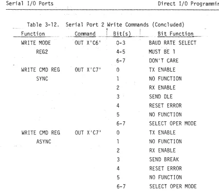
3-12. Serial Port 2 Write Commands
3-13. Disk -I/O Port Commands
3- 14. Pri nter I/O Commands
3-15. Board Status Port Commands
3-16.
3-17.
3-18.
Board Command Port Commands . Jumper Functions . . . Summary of I/O Port Addresses .
2
5
. . . . 6
. • • . 9
· . 12
· 21
· . 32
· 33
· . 36
· 38
· . 38
· . 41
· . 42
· .43
.44
· 45
· • 4·6
.46
· .48
.49
· 51
· .52 .53
· . 55
.56
· .57
· .58
.59
DEBUGGER USE OF THE CPU STACK
Upon entry to the Debugger, the stack pointer is set to a valid (non-protected RAM) address. When program execution is interrupted by the BREAK key or a breakpoint instruction, control is transferred to the Debugger which stores the machine status and registers on the stack and saves the stack pointer address. The user mayor may not reset the stack pointer
after the interrupt; Debugger execution will continue automatically in either case. Note, however, that if the user resets the stack pointer to an invalid address, the machine status display may show incorrect data.
The Debugger Execute command (E) stores the starting address on the stack, reloads the registers, and executes a return instruction. The return instruction transfers control to the execute address which is stored on the stack. If the stack pointer is not valid, the execute command will fail and the message liSP NOT IN RAMII will be displayed.
The liZ S=nll command is used to reset the stack pointer. Since the Debugger generates the machine status display from the data on the stack, the display changes each time the liZ S=nll command is entered.
Relocatable subroutines, including a number of I/O service subroutines, are available to the user. Service subroutines greatly simplify input/ output operations to standard peripheral devices. These subroutines may be actuated by execution of a CALL instruction (for 8080/85A/Z80) or JSR instruction (6800/02) to the appropriate entry point, as shown in Table 2-1.
I/O subroutines are provided for keyboard input/CRT display output, disk input/output, EIA send/receive, and cassette tape read/write functions. The routines have convenient calling conventions for use with the I/O devices. The routines interpret user requests and perform the detailed low-level I/O operations required to accomplish the requested operations.
Table 2-1. I/O Service Subroutine Functions
I/O Type __ . ______ .Global Label File Service Function _______________ .
Keyboard/ KEYIN KEYIN.R Read a character from the
key-CRT Display'· board or command file
Disk
EIA
Tape
MSGOUT
~~SG I N
TVOUT
DISPCUR OUTCUR BLNKCUR KBDIN KBDTST DISK DISKW EIASET EIAIN
EIAOUT READ READR WRITE REWIND
KIO.R
DIO.R
EIA.R
TIO.R
Write a message a line at a time to the CRT display
Read and echo a line from the keyboard
Write a character to the CRT display
Display the cursor Display the cursor Blank the cursor
Read a character from the keyboard Test for keyboard input
Entry to the disk routines Wait for completion of disk I/O Set EIA parameters
Input a character from the EIA port
Send a character to the EIA port Read a record from tape
Re-entry read from tape Write a record to tape Rewind tape Unit(s)
KEYBOARD INPUT/CRT DISPLAY OUTPUT
The keyboard and CRT display terminal may be addressed directly (see Section 3). However, a much easier method of accessing them is obtained by use of MSGIN and MSGOUT which access a line at a time; KEYIN and TVOUT which access a character at a time; the cursor display routines (DISPCUR, OUTCUR,
and BLNKCUR); and the bypass command file routines (KBDTST and KBDI~).
The TVOUT routine operates the CRT display in the following manner. Tne cursor is first initialized to the top left display location by output-ting a clear (DLE=X'10 ' ) character. The ASCII representation of the character to be displayed is then loaded into the accumulator* prior to calling the TVOUT routine. A cursor is displayed at the next character position. When that character is stored, the cursor is advanced, moving from the last character of the line to the first character of the following line. When the last character of the bottom line is reached, it moves to the first character of the top line.
A horizontal dividing line below the cursor (consisting of underline
) characters) separates the data most r~cently displayed (above the line)
from older data (below the line). As new data are received and entered onto
the display, the dividing line moves down. At the bottom of the screen it
wraps around to the top so that the data remain on the screen until they are written over on the next cycle. All registers and flags are saved.
The most commonly used control commands are interpreted as shown in Table 2-2.
Table 2-2. CRT Display Control Command Functions
Character Function
Carriage Return Moves the cursor to the left of the current
line. Line-Feed
Backspace DLE(X'10 ' )
Moves the cursor down one line. Moves the cursor back one space.
Keyboard and CRT Display Functions. The nine keyboard CRT I/O functions are defined below.
MSGIN
MSGIN reads a line at a time from the keyboard or command file and echoes the data on the display. MSGIN uses routines in the KEVIN.R,- LINEIN.R and KIO.R files.
MSGOUT
Displays a line at a time. When MSGOUT is called, a message is written
to the CRT display refresh page. The address of the message is passed in the
HL register pair (or Index register for 6800/02 systems). The message is terminated by X'OQ'.
KEVIN
KEVIN reads a character at a time from the keyboard or command file and
returns it in the accumulator. If the accumulator is zero when the routine
is called, the character is converted to upper case; if non-zero, lower case characters can be read. The Command File Processor and KEVIN use memory from X'D60Q' to X'D7FF' for the command file workspace. The user should not alter
this region if KEVIN is used. KEVIN uses the LINEIN routine (in file LINEIN.R)
and routines in file DIO.R.
TVOUT
Displays a character at a time. The accumulator must contain the char-acter to be displayed; no other parameters are used.
OISPCUR
When called, this routine displays the cursor. If the content of the
HL register pair/Index register is zero, the cursor is displayed at the next
location to be used by TVOUT. If the HL register pair/Index register has a
OUTCUR
OUTCUR is used to display the cursor when field attribute characters are present in the display refresh page (see Section 3) or when the cursor
location is in row-column form. At the time of invocation, the accumulator
should contain the column number and the B register/accumulator B should contain the row number.
BLNKCUR
This routine blanks the cursor. No parameters are used.
KBDIN
KBDIN reads a character from the keyboard and returns the result in the accumulator. This routine can be used to read from the keyboard even if command file processing is active.
---~---
---KBDTST
This routine tests the keyboard status register. If new data are
avail-able, the accumulator will be non-zero on return. If a keystroke has not
DISK INPUT/OUTPUT
FUTUREDATA RDOS allows user programs to implement all of the disk file management functions. These functions (Create, Delete, Open, Close, Read, Write, Rename, Change Attributes, and Free Space) are made available through a single entry point in the relocatable disk I/O package 010 (residing in file NDIO.R).
File Control Block. The Disk I/O service routines are invoked by
executing a call to the entry point, DISK. The instruction, CALL DISK (or
JSR DISK for 6800/02 systems), invokes the disk I/O package. The address
of a 26-byte parameter list (see Table 2-3) which is passed in the HL register pair/Index register, completely specifies the operation to be performed.
This list is called a File Control Block (FCB), and should be built in any
convenient area in read/write memory. The FCB is used to determine the
required function, file name, location of the I/O buffers, etc.
The Disk I/O routines return a completion code in the accumulator to indicate whether the operation was performed successfully, or if an abnormal condition was detected. When errors are detected, the HL register pair/
Index register points to the address of an ASCII message giving the nature
of the error. This message is terminated by a byte of zero and may be displayed by calling the MSGOUT I/O service subroutines.
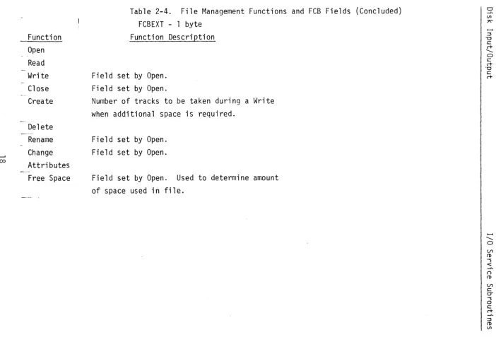
The 13 fields contained within the FCB are listed in Table 2-3. Table 2-4 shows the file management functions and how they relate to the FCB fields.
Field CBFLO
Table
B~tes
1
2-3. File Control
X100 1
X' 02 1 X' 04 1 X' 08 1 X'10 ' X' 20 ' X' 40 ' X' 80 '
Block Fields Function
- perform function defined by FCBFLl - create file
- open file - close file - delete file - rename file
Field FCBFL1
Table 2-3.
! .Bytes
1
FCBADR 2
FCBLEN 2
FCBSEC 2
FCBUN 1
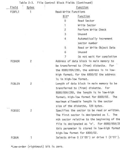
File Control Block Fields (Continued) Function Read-Write Functions
Bit* Function
0 Read Sector
Write Sector
2 Perform Write Check
3 Unused
4 Automatically increment
sector number
5 Read or Write Object Data
6 Unused
7 Do not wait for completion
Address of data block in main memory to be transferred to (from) diskette. For the 8080/85A/Z80, the address is in low-high format; for the 6800/02 the address is in high-low format.
Length of data block in main memory to be transferred to (from) diskette. For 8080/85A/Z80, the length is in low-high format; high-low format for 6800/02. The maximum allowable length is the sector size of the diskette, 128 bytes.
Specifies the sector to be read or written. The first sector is designated as 1. The nth sector relative to the beginning of the
file is designated as "nll. For 8080/85A/Z80
this parameter is stored in low-high format; high-low format for 6800/02.
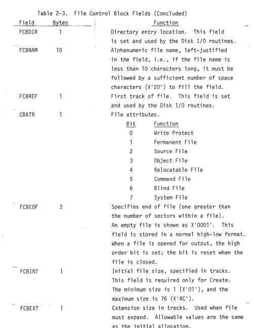
[image:14.620.80.565.117.738.2]Table 2-3. File Control Block Fields (Concluded) Field
FCBDIR
FCBNAM
FCBREF
CBATR
FCBEOF
FCBINT
FCBEXT
Byte s _ .... ,._ ... ___
i
110
2
Function
Directory entry location. This field is set and used by the Disk I/O routines. Alphanumeric file name, left-justified
in the field, i.e., if the file name is less than 10 characters long, it must be followed by a sufficient number of space characters (X ' 20 ' ) to fill the field. First track of file. This field is set and used by the Disk I/O routines. File attributes.
Bit Function
o
Write Protect1 Permanent File
2 Source File
3 Object File
4 Relocatable File
5 Command File
6 Blind File
7 System File
Specifies end of file (one greater than the number of sectors within a file).
An empty file is shown as X'OOOl I . This
field is stored in a normal high-low format. When a file is opened for output, the high order bit is set; the bit is reset when the file is closed.
Initial file size, specified in tracks. This field is required only for Create.
The minimum size is 1 (X'Ol I), and the
maximum size is 76 (X ' 4C ' ).
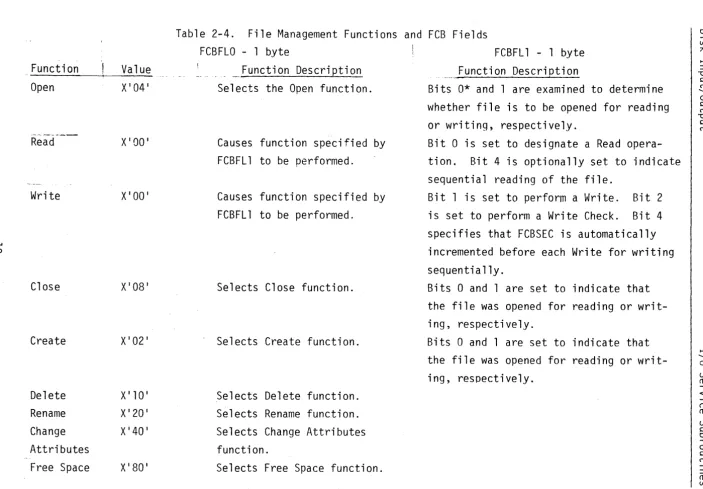
[image:15.620.51.554.103.753.2]Function Open
Read
Write
N
Close
Create
Delete Rename Change
Value
X'041
XIOO I
XIOO I
X'081
X'021
X 110 I
X' 20 ' X' 40 '
Function Description Selects the Open function.
Causes function specified FCBFLl to be performed.
Causes function specified FCBFLl to be performed.
Selects Close function.
Selects Create function.
Selects Delete function. Selects Rename function. Selects Change Attributes
by
by
Function Description
Bits 0* and 1 are examined to determine
whether file is to be opened for reading or writing, respectively.
Bit 0 is set to designate a Read
opera-tion. Bit 4 is optionally set to indicate
sequential reading of the file.
Bit 1 is set to perform a Write. Bit 2
is set to perform a Write Check. Bit 4
specifies that FCBSEC is automatically incremented before each Write for writing sequentially.
Bits 0 and 1 are set to indicate that the file was opened for reading or writ-ing, respectively.
Bits 0 and 1 are set to indicate that the file was opened for reading or writ-ing, respectively.
~. ()
CD
(/)
s:::
[image:16.797.39.743.55.544.2]w
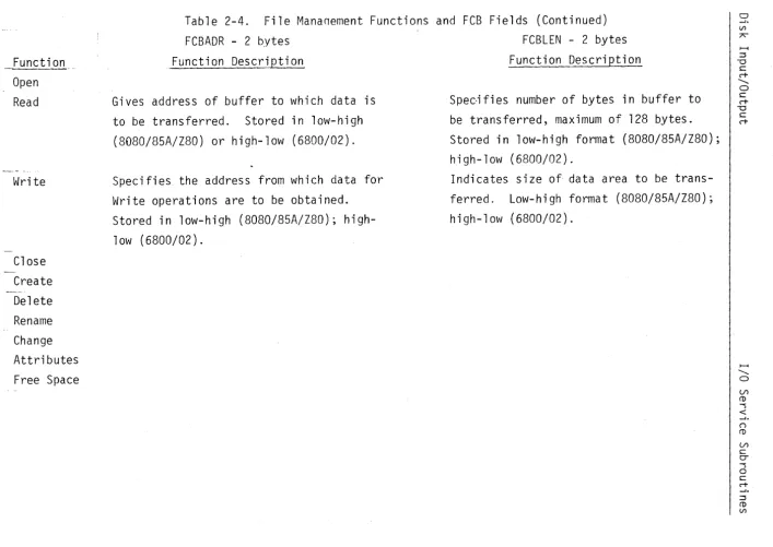
_ Functi 0fl. __ _
Open Read
Write
Close Create Delete Rename Change Attributes Free Space
Function Description
Gives address of buffer to which data is to be transferred. Stored in low-high (8080/85A/Z80) or high-low (6800/02).
Specifies the address from which data for Write operations are to be obtained. Stored in low-high (8080/85A/Z80); high-low (6800/02).
Function Description
Specifies number of bytes in buffer to be transferred, maximum of 128 bytes. Stored in low-high format (8080/85A/Z80); high-low (6800/02).
Indicates size of data area to be
trans-ferred. Low-high format (8080/85A/Z80);
high-low (6800/02).
1---4
""
o U>CD
"""S
<
(')
CD
U>
c:
0-"""S o
c:
c+
- J .
~ CD
[image:17.799.60.767.47.548.2]...j:::.
Function Open Read
Write
Close Create Delete Rename Change Attributes Free Space
Function Description
Specifies number of sector to be read. Stored in low-high format (8080/85A/Z80); high-low (6800/02).
Designates number of sector to be written. Low-high (8080/85A/Z80); high-low (6800/02).
Function Description
Specifies disk drive to be accessed. Drive number; field set prior to Open.
Field set prior to Open.
Field set prior to Open.
Selects disk drive to be accessed. Field set prior to Open.
Field set prior to Open. Field set prior to Open.
Field set prior to Open.
C rt
( )
(!)
(/')
C
0-Function Open
Read Write Close Create Delete Rename Change
<..n Attributes
Free Space
Field set Field set
Field set Field set Field set
Function Description
by Open. by Open.
by Open. by Open. by Open.
Function Description
Specifies 10-character name of file to be opened.
Field set prior to Open.
Specifies name of file to be created.
Contains new file name. Field set by Open.
Field set by Open. Field set by Open.
~ ...
o
(J")
CD """S <
( )
CD
(J")
s:::
0-"""S
o
s::: c+ - ' . :::::s CD
Function
"'--- --- - !
Open Read Write
--Close
Create
[~j'elete Rename Change Attributes Free Space
Function Description
Field set by Open. Field set by Open. Field set by Open.
Field set by Open. Field set by Open. Field set by Open.
Field set by Open.
Function Description
Field set by Open.
Field set by Open. May be reset prior
to Close if attributes are to be changed. Indicates which attributes are to be initially assigned to the new file. Field set by Open.
Field set by Open.
Field set by Open. May be updated prior
to execution of Change Attributes function. Field set by Open.
~
... o
(/)
m
"""'S <
(")
Function
-,--~~----...----,--- Function Description Function Description
Open
-_._----" --... ~ .. -.-~---..
-Read Write Close Create Delete Rename Change Attributes Free Space
Field set by Open. Field set by Open.
Field set by Open and updated during Write.
Field set by Open.
Field set by Open. May be updated prior to execution of Change Attributes function. Field set by Open.
Number of tracks to be allocated to file.
...;,I. ( )
ro
U'>
c
Ci -s o
c c+
Function Open Read Write Close Create
Delete Rename Change
co
Attributes Free Space
Function Description
Field set by Open. Field set by Open.
Number of tracks to be taken during a Write when additional space is required.
Field set by Open. Field set by Open.
Field set by Open. Used to determine amount
of space used in file.
...I.
()
CD Vl
[image:22.797.37.740.86.570.2]Diskette Directory. All diskettes used with FUTUREDATA RDOS must have a directory located on physical track zero. The directory is created when
the diskette is initialized with the "I" command in the File Manaqer. The
file name "DIR" is entered for the directory. DIR is given the "permanent" and "write protect" attributes. The purpose of the directory is to store the name of each file, its location on the diskette, its attributes, its current end-of-file location, and size of expansion when additional space is required.
The directory is made up of one sector containing a track map and ten sectors containinq file name information. The track map maintains a list of both unallocated tracks and those allocated to existing files. The file name sectors contain one entry for each file allocated on the diskette. Each
name entry is 16 bytes long. Eight entries fit into each 128-byte sector;
thus, ten sectors can accommodate a maximum of 80 entries, with a maximum of 76 usable sectors.
The following FCB fields are contained in each file name entry: FCBNAM (10 bytes), FCBREF (1 byte), FCBATR (1 byte), FCBEOF (2 bytes), FCBINT (1 byte), and FCBEXT (1 byte).
The file name entries are initialized with the Create function, removed with the Delete function, and changed with the Rename function. The file
Error Return Codes. A completion code is loaded into the accumulator upon return from the Disk I/O routines. This code indicates whether the requested function executed successfully, or whether an error condition was encountered. The accumulator is set to zero if no errors have been found. If an error has been detected, an error code is placed in the accumulator, and the HL register pair/Index register is set to point to an ASCII message describing the error. The error message is stored in memory as a sequence of ASCII characters followed by a zero byte indicating the end of the message. The error message may be displayed by the calling program.
N
I
\ I/O Routine Error
Messages
;
~_~~~Tn Code
I 0
PERM I/O ERR
2 END FILE
3 - DISK FULL
Definition Function completed successfully.
Unrecoverable error.
Readi ng of a sector i
beyond the end-of-fi 1 e 1
was reques ted. !
No space is available to expand the size of the file.
I
Open : Read t~ri te ! Close Crea te , De 1 ete Rename
x
X XX X
X
X
X
X
X
X X X
x
X Xx
4 - FILE NOT FOUND Specified file was not X
5 - DUPLICATE NAME
6 - PARM ERR
7 - DRIVE NOT UP
found in diskette directory.
File name specified is already used on the diskette.
Invalid field in FCB.
Selected disk drive not ready.
8 - PERM FILE File requested for
deletion has the permanent attribute.
9 - WRITE PROTECT Attempt was made to
open a file with the Write Protect attri-bute.
X
x
x
x
x
X
x
x
X
x
x
x
XX
x
x
x
x
X
X
X X
x
x
--r-Change Attributes X X X X X
I
, A
: Free ~
Space ~
Function Definitions. The file management functions are described in the paragraphs below.
Open Function. Before a file can be accessed on diskette, it must be "openedll
• The Open function uses the ASCII file name given in the FCB
to locate the file name entry in the diskette directory. This entry provides the information necessary for file access such as location on the diskette, end-of-file, etc.
Read Function. The Read function causes the disk unit to seek the requested file sector. Data from the sector are then transferred into the
memory buffer specified by the FCBADR field of the FCB. The diskette sectors
contain 128 bytes; the length to be transferred to memory (up to 128 bytes) can be explicitly specified in the FCB.
File sectors are numbered sequentially, starting with the number 1. The
sector to be read is contained in the FCBSEC field of the FCB. Even though
a file may be composed of a number of non-contiguous tracks, the Disk I/O routines automatically compute the location of the requested sector.
When a file is first opened, the FCBSEC field is set to zero. If direct
access to file sectors is required, the program must enter the sector numbers
in the FCBSEC field prior to each read request. If sequential accessing to
file sectors is desired, bit 4 of the FCBFLl field may be set so that FCBSEC will be incremented by the Disk I/O routines. The first Read request reads the first sector of the file, the second request reads the second sector, etc. Bit 4 specifies that the current value of the FCBSEC field will be automatically incremented by one, prior to each Read request.
Prior to each Read operation, the Disk I/O routines co~pare the requested
sector number with the end-of-file sector number in the FCBEOF field. If a sector beyond the end-of-file is requested, the Read function returns with code in the accumulator specifying an "end-file" condition.
FCBFLl field specify which operations are to be performed. Normally, both bits 1 and 2 should be set so that the Write and Write Check operations will be performed. However, if both operations are performed by one call, there is a delay of one diskette revolution (167 ms) between the Write and the Write Check, since the same sector must be accessed twice.
In some circumstances, it is possible to design a program so that a large
amount of data can be written sequentially from memory. In this case, a
significant amount of write time can be saved if all of the Write operations are performed first. FCBSEC must then be reset to the first written sector to perform the Write Checks.
When the Write and Write Check operations are performed separately, it is possible to write five sectors per revolution (30 sectors per second) and to Write Check five sectors per revolution.
As with the Read function, the file must be opened before a Write opera-tion can occur. The Write funcopera-tion requires the FCBADR field (specifying the address) and the FCBLEN field (specifying the file size) to define the memory buffer to be written to diskette.
FCBSEC designates the number of the sector to be written into. FCBSEC
is initialized to zero when the file is first opened. For direct writing,
FCBSEC is set by the program prior to initiating the Write operation. For sequential writing, bit 4 of FCBFLl must be set; the Disk I/O routines will then automatically increment FCBSEC prior to each Write operation.
Before writing to the diskette, the Disk I/O routines check that the sector number specified by FCBSEC is less than the end-of-file reference
in FCBEOF. Before a sector is sequentially written, FCBSEC is incremented
by one. If FCBSEC becomes greater than FCBEOF, the Disk I/O routines attempt
to allocate more space for the file. The number of tracks obtained when
an allocation extension is made is given by the value in FCBEXT. Sector
Close Function. The Close function updates the diskette directory with new or modified information, such as file attributes and end-of-file
location. If a file has been opened for reading only and no changes were
made to its directory entry (this is the usual case), the Close function is not manditory. However, if the file has been opened for writing, it is recommended that the file be closed since there is a possibility that infor-mation about the file or file length has changed.
The Close function can be used to set or change file attributes. This
is accomplished by changing the FCBATR field prior to execution of the function. Create Function. The Create function is used to set up new files on a diskette. Create automatically opens the file so that other functions can be performed directly after creation.
The size of the new file is specified by the FCBINT field. When the file is created, the attributes specified in FCBATR and the extension size speci-fied in FCBEXT are stored in the file's diskette directory entry for later use.
Delete Function. The Delete function is used to erase an existing file, return the previously allocated space to the free track pool, and remove the file's directory entry.
Rename Function. The Rename function is used to change the name of an existing file.
Change Attributes Function. The Change Attributes function allows the attributes of an existing file to be modified. The following FCB fields may be affected by this function: the attribute field (FCBATR), the end-of-file field (FCBEOF), and the expansion size field (FCBEXT).
Free Space Function. The Free Space function can ·be used to return unused tracks to the free track pool. When an existing file is rewritten, the new data may occupy less space than the data originally stored in the file. The Free Space function uses the current end-of-file, as specified by the FCBEOF field, and returns all tracks not needed by the new file to the
free track pool. If all of the tracks are used, the Free Space function
Overlapped I/O. The Disk I/O routines provide for processor execution overlapped with disk reading or writing. Overlapped I/O is selected by setting the high-order bit of the FCBFLl field. When overlapped I/O is
specified, the Disk I/O routines return to the calling program upon execution
of the disk Read or Write commands. To check for completion of the requested
operation, the user program must call the Disk routines a second time.
When a Read operation is desired, the first call to the Disk I 0 routines checks the parameters, starts the read function, and returns control to the calling program. The read operation transfers data from diskette into a sector-sized buffer contained in the disk control unit. The second call to
the Disk routines checks for completion of the Read. If the Read operation
has not been completed, the program waits. If the operation has been completed,
the data are transferred from the control unit buffer into the buffer specified in the FCB.
The Write operation is begun by the Disk routines' transfer of data from the buffer specified in the FCB to the disk control unit sector buffer. The Disk routines return to the calling program, and a second call is made to the
Disk routines. If the Write operation has not been completed, the program
waits. If the Write has been completed, the Disk routines return to the
calling program.
The Write Check process is similar to that of the Write operation. When overlapped I/O is selected, only one operation can be performed by a single
call to the Disk I/O routines. If both the Write and Write Check functions
are selected, only the Write operation will be performed.
The first call to the Disk routines, which initiates overlapped I/O, is
performed in the same fashion as calls for non-overlapped functions. For
the 8080/85A/Z80, the HL register pair contains the address of the FCB, and
the Call instruction references the Disk I/O entry point (DISK). For the
6800/02, the Index Register contains the address of the FCB, and the JSR instruction references the Disk I/O entry point (DISK).
The second call to the Disk routines, which completes the function,
references a secondary entry point (DISKW). The wait entry does not require
accumulator must be set to indicate one of the following actions: 1) if the accumulator is set to zero, normal processing will occur as described
above; 2) if the accumulator is set to non-zero (e.g., X'Ol I), the I/O
operation in progress will be terminated immediately.
Since both disk drives are accessed through the same control unit, it is not possible to perform concurrent operations to both disk drives. Thus, if the second disk drive must be accessed while operation is in progress on the first, one of two actions must be taken: 1) the operation on the first drive must be completed by a call with the accumulator set to zero, or 2) the operation must be aborted by a call with the accumulator set to non-zero. In the latter case, the operation must be restarted if the data are needed.
Return codes are generated by both the first and second calls to the Disk routines. An error check must be made following both the initial call
and the call completing the operation. If an I/O error is detected during
the second call to the Disk routines, automatic error recovery is attempted. The operation is re-tried ten times without returning to the calling program.
During error recovery, overlapped execution is temporarily suspended. If
Examples. The following paragraphs contain example sequences for creating, opening, reading, writing, and closing files using the 8080/85A/
Z80. When using the 6800/02, two-byte fields in the File Control Block
(B-type addresses) must be in high-low format (A-type addresses).
Reading From a File. In order to read from an existing file, the file must be opened. This is accomplished by calling the Disk routines with
the Open function selected by an X'04' in the first byte of the FCB. In the
examp 1 e be low, the FCB has the symbo 1 i c name "RFCB". RFCB is set uo in memory using Define Constant (DC) Assembler directives. The fields required by Open and Read are initialized in RFCB.
The instruction sequence for opening the file is as follows. Note: the
GLBL Disk directive must occur once (and only once) in an assembly that calls the Disk I/O routines.
(GLBL DISK EXTERNAL ENTRY POINT)
LXI H,RFCB MV I ~1, X' 04 I
CALL DISK ORA A JNZ ERROR MVI M,O
LOAD H,L WITH FCB ADDR SELECT OPEN FUNCTION CALL DISK ROUTINE CHECK RETURN CODE HANDLE ERROR RETURN
SELECT READ FUNCTION FOR LATER Sectors from the open file can be sequentially read by the following:
(GLBL DISK EXTERNAL ENTRY POINT)
XI H,RFCB LOAD H,L WITH ADDR OF RFCB
CALL DISK CALL DISK ROUTINE
ORA A CHECK RETURN CODE
JNZ ERROR HANDLE ERROR CONDITION
The File Control Block for the above operations is as follows:
RFCB DC 0 FUNCTION IS SET LATER
DC X' 11' SELECT READ
&
INCREMENTDC B(IBUF) ADDR OF READ BUFFER
DC B(128) LENGTH OF READ BUFFER
DC B(O) SECTOR # INIT BY OPEN
DC 0 DC 0
DC 'FILENAME
DC 0
DC 0
DC A(O) DC 0
DC 0
IBUF OS 128
Writing Into a File. The creating and writing into a file. following sequence:
(GLBL DISK LXI H, \ .. JFCB
MVI M,X ' 021
CALL DISK
ORA A
JNZ ERROR
SELECT UNIT ZERO FIELD SET BY OPEN FILE NAME
FIELD SET BY OPEN ATTRIBUTE SET BY OPEN EOF SET BY OPEN
ALLOCATE SET BY OPEN
EXTENSION SIZE SET BY OPEN READ BUFFER
example below shows the procedure for First, the file is created with the
EXTERNAL ENTRY POINT) LOAD FCBADDR
SELECT CREATE CALL DISK ROUTINE CHECK RETURN CODE HANDLE ERROR CONDITION
MVI M,O SELECT WRITE FUNCTION
If the user wishes to write into an existing file, the file can be opened
by selection of the Open function (X ' 041
) rather than the Create function.
When the file is being rewritten, the end-of-file field must be reset as follows:
LXI H,X'0100 '
SHLD FCBEOF
X'OOOl I REVERSED
SET TO X'OOOl I
(GLBL DISK
LXI H,WFCB CALL DISK ORA A JNZ ERROR
EXTERNAL ENTRY POINT)
LOAD FCBADDR CALL DISK ROUTINE CHECK RETURN CODE HANDLE ERROR CONDITION
After writing is completed, the file must be closed, as shown below.
(GLBL DISK EXTERNAL ENTRY POINT)
LXI H,WFCB ADDR OF FCB
MVI M,X'08' SELECT CLOSE
CALL DISK CALL DISK
ORA A CHECK RETURN CODE
JNZ ERROR HANDLE ERROR CONDITION
The FCB for wri ti ng is initialized by the following:
WFCB DC 0 FILLED IN DURING EXECUTION
DC X' 16' SELECT WRITE AND CHECK
DC B(OBUF) ADDR OF WRITE BUFFER
DC B(128) LENGTH OF WRITE BUFFER
DC B(O) SECTOR # SET BY OPEN
DC WRITE TO UNIT 1
DC 0 SET BY OPEN
DC 'WRITEFILE ' FILE NAME
DC 0 SET BY OPEN
ECBRATE. The ECBRATE field of the ECB contains a code which selects the transmission"and reception (Baud) rate. Sixteen rate codes
are allowed as shown in Table 2-7. Note: Using rate codes not listed in
the table produces unpredictable effects.
ECBL~. The ECBLEN field specifies the number of bits in the data
to be transmitted and received. Usual values are 5, 6, 7, or 8; other
character lengths cause unpredictable results. Transmission of the byte
passed in the accumulator begins with the low-order bit; e.g., \vhen 7 is
specified as the length, the low-order 7 bits are transmitted.
ECBUNIT. The ECBUNIT field selects which EIA port is to be
i nit i ali zed . ,A. val u e 0 f 0 n e s e 1 e c t s E I A po r t 1; a val u e 0 f bv 0 s e 1 e c t s E I A
port 2. The EIA routines assume that port 1 is configured to simulate a
t e nlli n a 1 and p 0 t~ t 2 ~ a III 0 d em. Aft e r i nit i ali z a t ion byE L!l. SET. po r t h o 1 d s
its Request to Send and Data Terminal Ready lines high (see Section 3 for
rno re in forma t ion) .
Field
-EC8FLAG
EC6R,;TE
EC8LEN
ECBUNIT
Table 2-6. EIA Send-Control Block
;; of Bytes
1
Functions
Contains flag bits having the following meaning:
Bit Function
o
Send break. Used by E I.A.OUT.Selects two stop bits for TTY.
2 Disables parity bit generation!
checking.
3 Selects odd parity.
4-7 Unused.
Transmission/reception rate select code (see Table 2-7).
Length (in bits) of characters to be transmitted/received.
Table 2-7. EIA Baud Rate Select Codes
Code ! Rate (Bits/Second)
n"'_~~._" .. _ .. . ...! ....
0 50
1 75
2 110
3 134.5
4 150
5 300
6 600
7 600
8 1200
9 1800
A 2400
B 3600
C 4800
D 7200
E 9600
F 19200
Examples.
ASCII Data Configuration. The most common application for the EIA send/receive routines is ASCII character data exchange. ASCII data have the following specifications:
Parity Stop Bits Length ECB Communication.
Yes/Even
Two for TTY, one otherwise 7 bits
The EIA control block (ECB) configuration for communication with a Teletype on EIA line 2 is as follows:
SCBFLAG = X'02'
SCBRATE
=
2SCBLEN
=
7The EIA control block configuration for communication with a modem at 300 Baud on EIA line 1 is as follows:
SCBFLAG
=
X'OO'SCBRATE = 5
SCBLEN
=
7SCBUNIT = 1
If it is necessary to control the Request to Send or Data Terminal Ready bits or to read the Clear to Send or Data Carrier Detect status on port 1,
CASSETTE TAPE INPUT/OUTPUT
The cassette I/O service routines provide for reading, writing, and
rewinding of cassette tapes. Data on cassette are formatted as fixed-length
records separated by inter-record gaps. The gaps are sufficiently long to
allow the tape to be stopped at the end of a record and restarted to read the next record. The tape I/O routines read or write a record at a time and automatically turn the tape units on and off.
The cassette tapes begin with a short length of plastic leader which must be bypassed before reading or writing begins. A flag bit indicating the first Read or Write causes the I/O routines to automatically space past the leader.
Parameters are passed to the I/O routines in the form of a 7-byte
write-control block (WCB) and a 6-byte read-write-control block (RCB). The control block
address must be loaded into the HL register pair/Index register prior to calling the Read or Write subroutines.
Error Recovery. For increased reliability, the I/O routines provide
for redundant recording of data records. Any number of copies of each record can be specified and will automatically be written by the cassette Write
routine. During reading, if an error is detected, the Read routine tries to
read the record again. If another copy is available, it is possible to
recover from the error. If the Read routine cannot find another copy, it
returns with an error code.
The error recovery scheme uses sequence numbers which are recorded with the data of each record. Thus, when an error occurs, subsequent data can be
automatically identified as another copy of the desired record. If the tape
is manually backed up for re-try, the sequence numbers are again used to identify the desired record.
WRITE. The WCB contains the fields shown in Table 2-8. These fields
represent seven sequential bytes in memory and provide the cassette Write
routine with the information necessary to process the request. For the
written, and automatically reset to zero afterward. Bits 1 and 2 of WCBFLAG are used in those cases where sequences of records are to be written without
inter-record gaps. When bit 1 is set to one, the Write routine leaves the
cassette unit on. (Normally, the unit is turned on before writing a record
and off afterwards). In conjunction with Bit 2, which suppresses the writing
of an inter-record gap, multiple records can be formatted without gaps. The gap in front of the data is usually necessary to allow the tape unit sufficient time to come up to speed.
The WCBADR field of the WCB specifies that the beginning data block address
be written to tape. The length of this block is specified by WCBLEN. Both
WCBADR and WCBLEN are 2-byte (16-bit) fields with the low-order byte stored before the high-order (8080/85A/Z80) or high-low (6S00/02) byte. The WCBUNIT
field specifies the tape unit to be addressed, either 1 or 2. Finally, the
WCBCOPY field specifies the number of record copies to be written. For maximum data density without automatic error recovery, one copy may be specified. For most other applications, two copies (providing a hard error rate of about one
in lxE12 bits) are adequate. All registers and flags in SOSO/85A/Z80 systems are saved and restored by the cassette write routine. The 6S00/02 version does not save the flags.
Field WCBFLAG
__ Bytes 1
Table 2-S. Write Control Block Function
Bits in this field request special functions as follows:
Bit Function
o
Flags Write of first record.1 Leaves tape unit on after Write.
2 Suppresses writing an
inter-record gap ahead of data.
Field WCBADR
WCBLEN
WCBUNIT WCBCOPY
Table 2-8. Write Control Block (Concluded)
2
Function
Address of data block to be written.
Address is stored in low-order byte format followed by high-order byte (8080/85A/Z80), or high-low format (6800/02).
Length of data block to be written.
Length is stored as low-order byte, followed by order byte (8080/85A/Z80), or high-low (6800/02).
Write unit (lor 2).
Number of copies of data to be written.
READ. The read-control block contains the fields shown in Table 2-9.
These fields represent six sequential bytes in memory and provide the Read routine with the information necessary to process the request. As with the Write routine, the control block address must be loaded into the HL register/
Index register prior to calling. For the first tape read, bit 0 of RCBFLAG is set to one. This causes the Read routine to reset the record sequence number counter to zero in order to begin reading a new tape. The bit is
automatically reset to zero after the first read. Bit 1 of RCBFLAG specifies
that the cassette unit is to remain on after the Read, allowing Reads where inter-record gaps are not written.
---Field RCBFLAG
RCBADR
RCBLEN
RCBUNIT
Bytes
1
2
2
Table 2-9. Read-Control Block Function
Bits of this field request special func-tions as follows:
Bit Function
o
Flags Read of first record.Leaves tape unit on after Read.
2 Accepts record with any
sequence number.
3-7 Unused; should be O.
Address of data block into which data from tape is to be placed. Address is stored as low-order byte, followed by high-order byte (8080/85A/Z80) or high-low (6800/02). Length of data block. Length is stored as low-order byte followed by high-order byte (8080/85A/Z80) or high-low (6800/02). Read unit (lor 2).
The RCBADR and RCBLEN fields specify the address and length of the read memory area. Both fields are two bytes (16 bits) long, and values are stored with the low-order byte first. RCBUNIT specifies the read unit; either 1 or 2.
Upon return from the Read routine, the accumulator contains a completion code: zero for success, non-zero for error. Several types of errors are classified by the value of the return code as follows:
Table 2-10. Tape Read Routine Error Codes Code
2
Definition
Table 2-10. Tape Read Routine Error Codes (Concluded)
---~~--.J
.... __ ... __ .. __ ... __ ...
Defini ti on3 No data have been read from the tape for an unusual
length of time. Possibly, a blank tape is being read.
All registers except the accumulator and the flag bits are saved and restored by the cassette Read routine. For the 6800/02, the Index register is saved.
READR. If a type "l" error is detected,' recoveYlY shoul d be attempted as follows. After the operator manually rewinds the tape for several seconds, the cassette Read re-try routine should be called. This call requires no
parameters. It causes the Read routine to search for the record by sequence
number, and then attempts to reread the data. The re-try routine also
returns a completion code. An error detected after re-try probably indicates an unrecoverable error. The bad record can be skipped by calling the regular Read routine again.
The re-try routine saves and restores all registers except the accumulator and the flag bits in 8080/85A/Z80 systems. The 6800/02 saves only the Index regi s ter.
Cassette Rewind Routine. When called, the Rewind routine turns on the selected tape for rewinding and waits for operator acknowledgement of comple-tion (pressing the RETURN key). When this signal is received, the unit turns off.
Rewind requires the address of an RCB or WCB in the HL register pair/ Index register. The control block specifies the tape unit to be rewound. The routine also sets bit 0 of the control block to prepare for reading or writing of a new tape. The assumption is made that since the current tape has been rewound, a new tape will follow.
For 8080/85A/Z80 systems all registers ,and flags are saved and restored
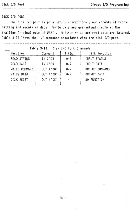
The I/O service routines in KIO.R, KEYIN.R, LINEIN.R, DIO.R, EIA.R, and TIO.R provide high-level interfaces for the standard peripheral devices. However, for some applications, it may be necessary to access these devices directly. Section 3 contains the information needed to perform this task. The I/O addresses shown on the following pages apply to 8080/85A/ZaO systems. 6800/02 addresses must be mapped into memory.
All 6800/02 I/O addresses are located between X'DOOO ' and X'DFFF'; e.g., the equivalent of an 8080/85A/Z80 IN X'FO ' command is LDAA X'DOFO ' . Similarly, an OUT X' F31
command is translated to STAA X' DOF31
for 6800/02 systems. All of the 6800/02 memory reference instructions may be used with the I/O devices. However, output-like commands (CLR for example) may cause problems. Commands
of this type generate a read cycle at the designated I/O address. In some
cases, the read I/O commands are used as reset signals. For example, the X' F21
and IN X' F31
KEYBOARD INPUT
A status bit, interrupt mask bit and four I/O commands are associated
with the keyboard. The I/O commands are summ~rized in Table 3-1.
-~--
---Table 3-1 . Keyboard Input Commands
I/O CMD I Function I/O Bit Assignments
. '" -.. ~ ...
7 6 5 4 3 2 0
IN X'FO' Read data Data Data Data ' Data Data Data Data Data
7 6 5 4 3 2 0
IN X'Fl' Read sta tus jmpr brk stat
IN X'F2' Reset status
OUT X'Fl' Set mask act kbd brk key
led led mask mask
When a key is depressed, the keyboard status bit is set to one. The IN X'Fl' command reads the status and moves it to the low-order bit of the
accumulator, where it can be read by the IN X'FO' command. Keyboard data are
valid only during the time that keys are depressed; therefore, data must be read within approximately 100 ms from the time the status bit is set to one.
The status bit remains set until reset by the IN X'F2' command. The low-order
seven bits of the data byte from the keyboard contain the ASCII encoding of the character entered.
The interrupt mask bit can be used to enable interrupts from the keyboard status bit. When the master system reset is generated at power-on or by the RESET key, the mask bit is cleared and keyboard interrupts are disabled. The keyboard interrupts are enabled when the "set mask" command (OUT X'Fl ') outputs an X'Ol'. CPU interrupts must be enabled by an "EI" instruction (ClI for
6800/02) before they can be accepted.
The interrupt causes a CAll to location X'0028' for 8080/85A/Z80 systems
or a JSR to location X'FFF8' for 6800/02 systems. CPU interrupt processing
BREAK KEY
The BREAK key is provided as an interrupt-gener~ting escape key and is
used by the Debugger for this function. Note: the status and mask bits
are separate from those of other keyboard characters.· A status bit, an interrupt mask, and three I/O commands are provided for the BREAK key as summarized in Table 3-2.
Table 3-2. Break Key Commands
I/O CMD Function
I
l/n Bit Assiqnments
7 6 5 4 3 2
- - - -.. - i
IN X'Fl I Read status stat
IN X' F31
Reset status
-OUT X'Fl I Set mask mask
When the BREAK key is depressed, the break status bit is set to one~
The IN X'Fl I command moves the status bit into bit 1 of the accumulator. The IN X' F31
command resets the status bit.
0
The mask bit can be used to enable interrupts from the break status bit. BREAK key interrupts are disabled when the master system Reset clears the
break mask bit, or when the OUT X'Fl I command outputs an XIOOI. When the
OUT X'Fl I command sets the mask bit to one, BREAK key interrupts are enabled. An "EI" instruction enables the CPU for recognition of the interrupts in 8080 systems. A "SIM" instruction enables RST 5.5 in the 8085A and allows
the interrupt to be recognized. In 6800, 6802 and Z80 systems, BREAK key
interrupts are vectored through the Non-Maskable Interrupt; thus, the "SEI" and IClI" or "EI" and "01" instructions have no effect.
The BREAK key interrupt causes a CAll (or JSR) to location X' 0020 ' in
8080 systems, X'FFFC ' (Non-Maskable Interrupt) in 6800 systems, X' 661
CRT DISPLAY SELECT
The CRT display interface is able to refresh the display from any 2K
page .in memory. The display page is selected as shown below in Table 3-3.
---~---~---~---Table 3-3. CRT Display Select I
I/O C~1D Function I/O Bit Assignments
7 6 5 1 4 3 2 r
a
!
OUT X'FO' Addr slct Addr Addr Addr Addr Addr . Addr
15 14 13 12 11 10
---~---~---.---CRT display address selection is accomplished by loading the accumulator with the high-order byte of the display page address and executing the
OUT X'FO' command.
CRT DISPLAY OUTPUT
Since the CRT display is refreshed from memory, direct output is accom-plished by storing data in the memory page selected for refresh. Data are converted by the CRT display module into a video signal which represents each ASCII code as a 9 x 7 dot matrix. Since only 128 displayable characters are generated, only the low-order seven bits of each byte are required for the display. The high order bit is used to select display field attributes as shown in Table 3-4.
Table 3-4. Display Code
X'80' X'8l' X'82' X'90' X'83' X'9l' X'92' X'93'
CRT
I
Field Attributes Function
Reset display to normal mode Highlight display
Blink display
Reverse video display Blink and highlight Reverse and highlight Reverse and blink
Reverse, blink and highlight
Each field attribute character occupies one memory location, but does not occupy any of the display locations. Thus, the CRT display buffer size is fixed only if the number of display attribute codes is fixed.
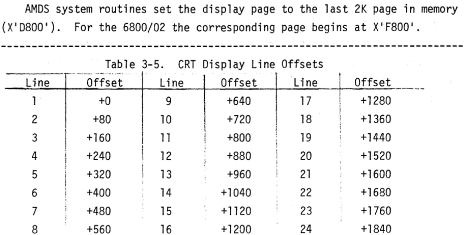
When there are no field attribute codes, the display is formatted from the CRT refresh memory as follows. The character at the top left of the screen is generated from the first byte. Subsequent bytes correspond to sequential characters across the 80-character line, with the next line using the next 80 characters, etc. Table 3-5 shows the offsets from the beginning of the display page, corresponding to the first character of each line
AMOS system routines set the display page to the last 2K page in memory (X ' D800 ' ). For the 6800/02 the corresponding page begins at X·F800 ' .
Line 1 2 3 4 5 6 7
8
Table 3-5. CRT Display Line Offsets
__ ... __ .~_N._~_"""~
Offset +0 +80 +160 +240 +320 +400 + 480 +560
I
ir I
i
!
;
Line 9 10 11 12 13 14 15 16
I
I
1
1
I
"
Offset +640 +720 +800 +880 +960 +1040 + 1120 +1200
Line 17 18 19 20 21 22
3 2 24
~
Offset! +1280
i
j +1360
;
;
, +1440
[image:47.623.65.529.100.334.2]MEMORY PROTECTION
Each 8K memory block contains an 8-bit protection register which can
be read and reset by I/O commands. Each register bit indicates the
write-protect status of a lK page of the block. The write-protection I/O commands are summarized in Tables 3-6 and 3-7.
Table 3-6. Protect Command Bit Assignments
7 6 5 4 3 2
o
Page 7 Page 6 Page 5 Page 4 Page 3 Page 2 Page 1 Page 0
---Table 3-7. ~1emory Protect Commands
I/O CMD Function
IN X 11 F I read module 0 protection (X'0000'-X'1FFF')
IN X' 3F ' read module 1 protection (X'2000'-X ' 3FFF')
IN X' 5F ' read module 2 protection (X'4000'-X ' 5FFF')
IN X' 7F ' read module 3 protection (X ' 6000 ' -X'7FFF')
IN X' 9F ' read module 4 protection (X ' 8000 ' -X ' 9FFF')
IN X'BF ' read module 5 protection (X'AOOO'-X'BFFF')
IN X'DF ' read module 6 protection (X'COOO'-X'DFFF')
6800 read module 6 protection (X'EOOO'-X'FFFF')
OUT X 11 F I set module 0 protection (X'OOOO'-X'1FFF')
OUT X' 3F ' set module protection (X'2000'_X ' 3FFF')
OUT X' 5F ' set module 2 protection (X'4000'-X ' 5FFF')
OUT X' 7F ' set module 3 protection (X ' 6000 ' -X'7FFF')
OUT X' 9F ' set module 4 protection (X ' 8000 ' _X ' 9FFF')
OUT X'BF ' set module 5 protection (X'AOOO'-X'BFFF')
OUT X'DF ' set module 6 protection (X'COOO'-X'DFFF')
The low-order bit of the protection register is assigned to the first lK page of the block, the high-order bit is assigned to the last lK page, and the other bits are assigned to respective lK pages. A bit set to one causes a write request to be inhibited at any address in the corresponding lK page.
A bit set to zero allows writing into memory. Execution of the boot PROM
REAL-TIME CLOCK
The Multipurpose I/O card (MPIO) contains a three-channel real-time clock. Two channels are dedicated to the high speed serial data link and are not directly available to the user. The third channel is available to the user as a programmable clock or interval timer. The I/O ports associated with the real-time clock are shown in Table 3-8.
Table 3-8. Real-Time Clock Commands
I I
Bit(s)
Function Command Bit Function
READ RTC IN X'CA ' 0-7 COUNTER LSB'S
READ RTC IN X'CA ' 0-7 COUNTER MSB'S
-LOAD RX CLOCK OUT X' C81
0-7 COUNTER LSB'S
LOAD RX CLOCK OUT X' C81
0-7 COUNTER MSB'S
LOAD TX CLOCK OUT X' C91
0-7 COUNTER LSB'S
LOAD TX CLOCK OUT X' C91
0-7 COUNTER MSB'S
LOAD RTC OUT X'CA ' 0-7 COUNTER LSB'S
LOAD RTC OUT X'CA ' 0-7 COUNTER ~~SB IS
LOAD CTL ~~ORD OUT X'CB ' 0 1
=
BCD, 0=
HEX1-3 COUNTER MODE
4,5 MSB, LSB SELECT
6,7 COUNTER SELECT
TRIGGER RTC IN X'CE ' NO FUNCTION
---
.
SERIAL I/O PORTS
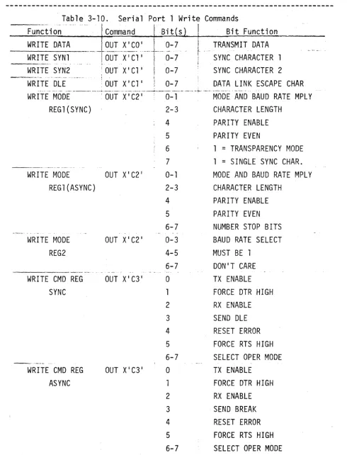
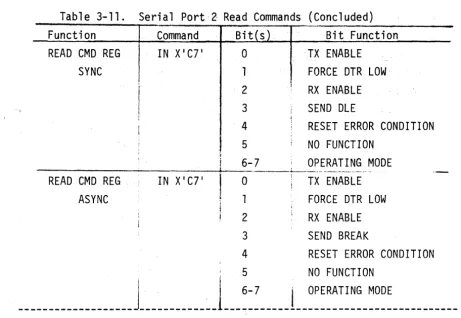
The MPIO card includes two serial I/O ports which are implemented by LSI USART's. There are four input and four output addresses associated with each port. Port 1 uses X'Cl I through X' C3 1, and port 2 uses X' C4 1 through X' C71. The functions for both ports are listed in Tables 3-9 through 3-12. For more information on serial I/O port programming, refer to the 2651 "Programmable Communications Interface" specifications in the appendix.
Table 3-9. Serial Port 1 Read Commands
:~~~t~~;A---'-' '~~~~~~~-,
.
B~~/
t-'INP~~\:~~ction--_._--_ ... _ ... -.-•. -... _. . ... __ .. __ . __ ... _._.. .-... _-_ .. --... ~ •. ---... -... " .... '-- ... . . . .
READ STAT REG IN X I Cl' 0 TX REG EMPTY
SYNC
READ STAT REG ASYNC
IN X'Cl '
2
3
4
5
6
7
o
1
2
3
4
5
6
7
-R-E-A D-M-OD-E-R-E-G--~---fN-X-'
C2-'---O _.,.--_._ .. _[ .
SYNC(REG1) 2-3
4
5
6
7
I
RX REG EMPTY
CHANGE IN DCD OR DSR PARITY ERROR OR DLE OVERRUN
SYNC DETECT DCD HIGH DSR HIGH TX REG EMPTY RX REG EMPTY
CHANGE IN DCD OR DSR PARITY ERROR
OVERRUN
FRAMING ERROR DCD HIGH DSR HIGH
MODE AND BAUD RATE MPLY CHARACTER LENGTH
PARITY ENABLE PARITY EVEN
Table 3-9. Serial Port 1 Read Commands (Concluded)
Function I Command ! Bit(s) Bit Function
I
READ MODE REG IN X' C21
0-1 MODE AND BAUD RATE MPLY
ASYNC(REG1) 2-3 CHARACTER LENGTH
4 PARITY ENABLE
5 PARITY EVEN
6-7 NUMBER STOP BITS
READ ~~ODE REG IN X' C21
0-3 BAUD RATE SELECTION
(REG2) 4-5 r~UST BE 1
6-7 NO FUNCTION
READ CMD REG IN X' C31
0 TX ENABLE
SYNC 1 FORCE DTR HIGH
2 RX ENABLE
3 SEND OLE
4 RESET ERROR CONDITION
5 FORCE RTS HIGH
6-7 OPERATING MODE
READ CMD REG IN X' C31
0 RX ENABLE
ASYNC 1 FORCE DTR HIGH
2 RX ENABLE
3 SEND BREAK
4 RESET ERROR CONDITION
5 FORCE RTS HIGH
Table 3-10. Serial Port 1 Write Commands
Function Command Bit s Bit Function
WRITE DATA LOUT X1C0 1 0-7
WRITE SYNl
----j-6ui---x··7Ci·,
.·.--I-.···.0-7- - _ . - - -•.... '. .... .'.' ~. !
WRITE SYN2 i OUT X'Cl '
I
0-7_ . _ .. __ .. ., ... - . .. '."." ... - - - - . . . , I
WRITE OLE :OUTX'Cl ' ! 0-7
I TRANSMIT DATA
t ....
SYN~ CHARACTER 1!
~ SYNC CHARACTER 2 DATA LINK ESCAPE CHAR
. . ,
._ ... __ . _._ .. _. , __ .• _ _ _ ._H • ___ ._._ .. ___ ._ ... _. _____ ._. __ .. ~_~ __ ._. _____ ... __ ... _ ... -__ .. _. ___ ... _. __ , - ..
WRITE r~ODE ' OUT XI C2 1 0-1 MODE AND BAUD RATE MPLY
REG1(SYNC) 2-3 CHARACTER LENGTH
4 PARITY ENABLE
5 PARITY EVEN
6 1
=
TRANSPARENCY MODE7 1
=
SINGLE SYNC CHAR.-_._._ ... __ .... _ ...
WRITE MODE OUT X' C2 1 0-1 MODE AND BAUD RATE MPLY
REG1(ASYNC) 2-3 CHARACTER LENGTH
4 PARITY ENABLE
5 PARITY EVEN
6-7 NUMBER STOP BITS
WRITE MODE OUT X' C2 1 0-3 BAUD RATE SELECT
REG2 4-5 MUST BE 1
6-7 DON'T CARE
. ", . . . ~ .--. .. ,
WRITE CMD REG OUT X' C3 1 0 TX ENABLE
SYNC 1 FORCE DTR HIGH
2 RX ENABLE
3 SEND OLE
4 RESET ERROR
5 FORCE RTS HIGH
6-7 SELECT OPER MODE
_.--_ ..
-WRITE CMD REG OUT X' C3 1 0 TX ENABLE
ASYNC 1 FORCE DTR HIGH
2 RX ENABLE
3 SEND BREAK
4 RESET ERROR
5 FORCE RTS HIGH
6-7 SELECT OPER MODE
[image:53.626.55.546.89.732.2]