P E R P U S T A K A A N U T H M
^ ^
Newcastle
University
Sonar Sensor for an Autonomous Mobile Robot
Author : M o h a m e d Najib Ribuan
Course Title : Msc Mechatronics
Supervisor : Dr Robert Bicker & Dr John Hedley
Academic Year 2006/07
Declaration
I herewith admit and declare that the content of this report as well as all the works accomplished in this project was entirely my own piece of works. Any information or works which were not belong to me were acknowledged and recognized as references. Any similarities found in this report were not intended to damage any copyright or properties o f t h e respective proprietor.
List of Contents Page
Acknowledgement vi
1.0 CHAPTER 1 - INTRODUCTION
1.1 Overview 1
1.2 Aims and Objectives 2
1.3 Significance of Works 3
1.4 Thesis Outline 3
2.0 CHAPTER 2 - BACKGROUND
2.1 Mobile Robot System 5
2.2 Proximity Sensors 10 2.3 Sensors for Ranging 12 2.4 Specification Requirement and Sensor Evaluation 13
3.0 CHAPTER 3 - LITERATURE REVIEW
3.1 Background of Sonar 16
3.2 Sonar Application 18 3.3 Sonar Limitation 19
4.0 CHAPTER 4 - THEORY AND MODELLING
4.1 Sound Navigation and Ranging (SONAR) 22
4.2 Time of Flight (TOF) 23 4.3 PIC Microcontroller 24 4.3 Design of Sensor Holder 26 5.0 CHAPTER 5 - EXPERIMENTAL SYSTEM
5.1 Hardware Design 28
5.1.1 Circuit Diagram 29
5.1.2 Electronics Components 32
5.2 Software Design 33
6.0 CHAPTER 6 - DESIGN OF EXPERIMENT
6.1 Experiment Setup 37
6.2 Equipment 38 6.3 Procedure 39
CHAPTER 1
1.0 I N T R O D U C T I O N
1.1 Overview
In general, this dissertation is about to investigate an obstacle detection and collision avoidance system for a mobile robot. The system described is for a mobile robot working in indoor environment specifically in a hospital and a healthcare centre. With a rapid development of mobile robot technology, the identification of the best system for the mobile robot working in the specific condition has been very crucial. Number of factors need be considered such as performance and cost in order to determine an optimum solution to the application.
In this work, an obstacle is defined as an object which prevents the robot from moving to its goal or its final location. These objects comprise from dynamic and static obstacle. For instance, walking humans as well as patients are considered as dynamic obstacle whereas wheelchair and hospital bed are an example of static obstacle. Hence, a sensor capable for detecting these kinds of objects is very crucial to avoid any collision which would cause a chaos in the specific environment. Thus it also enables the robot to achieve its final destination such as to attend patient for serving food on supplying medicine instead of nurse assistance that experiencing shortage, currently.
Newcastle University'
two parts as well, static obstacle (static environment) and collision avoidance
for a moving object (dynamic environment).
The mobile robot developed in this project is aimed to give a contribution to a
IWARD project which stands for Intelligent Robot Swarm for Attendance,
Recognition, Cleaning and Delivery. The project aim is to give a solution of
outnumbered staff in hospital/ healthcare center that becomes a critical
problem in European countries especially in UK for the past few years. The
robot are expected to be able to deliver support in the hospital such as
monitoring hospital wards, recognizing patient who need attention, providing
information about the patient location as well as cleaning and servicing patient
including delivering food, medicine and clothes. The robots work in group
thus beside detecting human or any obstacle it has to be able to detect their
associate as well. More information about the project is available at
http ://www. i ward, eu/cms/.
1.2 Aims and Objectives
The aim of this study was first, to produce a sensor system for obstacle
detection and collision avoidance for a mobile robot. The system is only a part
of a few components in the mobile robot system. Besides a wide range of
sensor such as sonar, radar and lidar a proper sensor for the application need to
be identified for the application. Secondly, the system developed is from
off-the-shelf components both hardware and software to achieve minimal cost yet
reliable to give good result. The sensor, in fact, is able to give a different
output for every different distance measured continually as a result of good
hardware and software implementation. Finally, the system is tested and its
performance is investigated with experimental works in order to provide
technical information to the developed system.
The objective of this work was to provide a detection system for a mobile
robot to be able to move inside hospital/ healthcare environment without
very crucial especially when the robot works in hospital where it has to
interact with patient as well as human such as doctors, nurses and visitors
Secondly, the objective of the project was to establish a low cost system for
the application. The constructed system is from off-the-shelf components as
the number of the robot for the application must be tremendous. However the
performances of the developed sensor are uncompromising. In addition, the
sensor system generated need to be flexible and able to integrate with different
application. This modular concept of the system will offer an advantage to
attach to any system where the obstacle detection and collision avoidance are
crucial for their application.
1.3 Significance of Works
This work contributes to a number of significance subjects. First, a reliable
and low cost system for obstacle detection and collision avoidance for mobile
robot is produced to secure the robot from hitting any object inside a hospital
or healthcare centre which might cause an injury especially to the patient.
Secondly, with the capability of the system an intelligence robot is generated
where it can decide the optimum path to avoid the object by processing the
input from the sensor system. Consequently, this will improve the existing
system which is also the third contribution of this work. Finally, with this
intelligence system it might not only used for the robot but capable to integrate
with different application. For example, this system might be used in
automotive industry such as to the busses or heavy vehicles. It will benefit in
reduction of accident rate among heavy vehicles which usually result to
catastrophe.
1.4 Thesis Outline
This thesis is organized as follows. Chapter 1 introduce the theme of the
Newcastle University'
well as the aims and the objectives of the work followed by the significance of
the investigation.
In Chapter 2, the background of the project is discussed. This will cover an
extensive explanation about mobile robot system as well as sensors used for
obstacle detection and collision avoidance system. A wide range of sensor
available for the application is also explained followed by the evaluation of
each sensor to determine the best sensor for the application.
A literature review in Chapter 3 discussed about the selected type of sensor.
This includes the background of the sensors, its application as well as the
limitation confine the ability of the sensor.
Chapter 4 contains a detailed description of the theory and modeling of the
system in order to develop the hardware and software of the system. The
components involved as well as the costs incurred are also listed.
The components involved as well as the costs incurred are listed in
experimental system for both hardware and software in Chapter 5. The
functions of each of the component are also explained in this chapter.
Chapter 6 explains in details about the experiment conducted to investigate the
performance of the system. This includes the experiment setup, setting of
equipment as well as the procedure in executing the experiment.
The result of the experiment is shown in Chapter 7. An explanation also been
given on how the result is obtained to give a clear vision about the data
achieve from the experiment.
Finally, the Discussion, Conclusion and Future Works are described in Chapter 8. The finding of this works is discussed and this gives the answer to
CHAPTER 2
2.0 BACKGROUND
2.1 Mobile Robot System
Robots ability and their function had been skyrocketed in the past few years
especially in industrial application as well as educational level. More and more
robots were invented with sophisticated and multitask function. Among the
famous robot introduced to the public were humanoid robot Asimo by Honda
Corporation and Swimming Robot from Massachusetts Institute of
Technology (MIT). These progresses had showed that robots become
important to human environment especially in future generation.
Generally, robot can be divided into 2 categories, industrial robot and mobile
robot. Industrial robot is designed specifically for industrial application where
the task may cause hazardous for human life or a repetitive job such as pick
and place. Hazardous environments like excessive heat, noise, fumes and
sparks in manufacturing processes; welding, spraying and moulding for
instance, may put the workers to harm an injury. Therefore robot becomes
perfect commutation for human in addition to decrease human error when
conducting the manufacturing process which results in poor production and
quality.
This industrial robot also referred as robotics arm or robot manipulator. It has
several configurations such as cartesian, cylindrical, spherical, articulated and
scara which actually describes the workspace of the robotics arm. The
configuration is basically base on type of joint of the robot arm whether it is
prismatic or revolute type joint. Nonetheless, articulated robotics arm is
widely employed in many industrial applications where it comes from
Newcastle University'
Among manufacturer of industrial robot available in the market at present are
ABB, Denso Robotics, Fanuc Robotics and Staubli Robotics.
Another category of robot is a mobile robot which becomes the topic of
interest. It can be sub-divided into 3 more categories, legged robot, wheeled
robot and anthropomorphic robot. Legged robot usually referred as walking
robot or crawling robot is a type of robot with number of legs. The number
begins from only a single leg up to twelve legs and it depends on a few aspects
including robot body, stability and of course the robot functional.
In order to move, legged robot requires an analysis of foot placement which
forms a point of contact with the ground referred as gait. The stride of the
movement however is called trot gait. The gait analysis is different for
different speed of movement such as walking and running. Therefore the
analysis of the gait becomes essential since it governs the robot stability as
well as the robot speed. An example of single legged robot was designed by
MIT in 1995 which called 3D One-Leg Hopper and a six-leg robot, Servobot
designed by Indiana University.
Wheeled robot was defined by Muir and Neuman (1986) as a robot capable of
moving on any surface merely by the actuation of wheel incorporated in the
robot which has constant contact with the ground. In term of stability, wheeled
robot has a better stability in comparison to the legged robot especially in
dynamics behaviour. However it also subjected to the wheel configuration the
robot employed. In the next paragraph, wheeled robot is discussed extensively
excluding the anthropomorphic robot which is briefly introduced to cover the
area of investigation.
Among many types of robot, wheeled robot was the favourite for many
including students, hobbyists and beginners interested in building a robot. This
is because the simplicity and straight-forward functional of the components
involve in constructing the robot. For instance, mobilerobots.com provides a
wide rage of Pioneer robot and Seekur robot used to perform tasks like
example was from popular kid toys, Lego that provides HandyBug a Lego
Mindstorms based robot as an early introduction for the beginner interested in
[image:13.600.74.519.146.501.2]mobile robot construction.
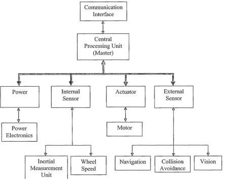
Figure 2.1 Mobile robot system components
Basically, a mobile robot consists of a system illustrated in Figure 2.1. The
system comprises of Central Processing Unit (Master) as the main controller
of the robot. It controls each sub-component of the system such as Power
Component, Internal Sensor Component, Actuator Component and External
Sensor Component. These sub-components will send the information as an input to the master controller whenever it is needed and this is in fact a two
way communication between the master and the sub-components. There are
Newcastle University'
available such as RS 232, RS 485, Modbus and Control Area Network (CAN)
bus subject to the requirement of speed and number of sub-component.
Power component provides the power supply for all the electrical and
electronic components in the robot system. Since it has to be mobile, the
power component usually acquired from battery pack or rechargeable battery.
The battery type includes lead-acid, nickel-cadmium (NiCd), nickel metal
hydride (NiMH) and lithium-ion (Li-Ion) cell. Number of aspects need to be
put into consideration in order to select a proper type of power pack. For
instance, the operating voltage, output current, operating time, charging time
and total weight of the power pack are among the important elements to think
as it determines the operating time of the robot in total.
Meanwhile, an autonomous power system is a power component with its own
power management system capable to acknowledge the main controller about
the level of the power available. Upon receiving the information, it will decide
to go to the docking station for recharging thus preventing the robot from
stalling on the pathway. Since the power required to operate the robot is a
direct current (DC) supply a power electronics module is required for charging
the battery at the docking station where the normal operating voltage and
frequency is 240 VAC and 50 Hz.
Internal sensor for a mobile robot can be described as a sensor which provides
information for its own system. For instance, an encoder placed on the motor
shaft will give information about position and rotating direction upon
controlling the motor. Another example of internal sensor is Inertial
Measurement Unit where it comprises an accelerometer for acceleration
measurement and gyroscope to maintain the orientation of the robot.
For a basic mobile robot that only can move without carrying any task the actuator involves is merely a motor to drive the robot. There are a few factors
that must be put into account when selecting the motor. The total weight of
robot, maximum speed, operating speed, power consumption as well as torque
considered before choosing number and type of motor that will be used.
Several type of motors available for selection including stepper motor,
brushed motor, brushless motor and smart motor available from Animatics.
In contrast, an External Sensor Component consists of a number of sensors to
make the robot interacts with the environment. For example a navigation
system, collision avoidance system and vision system enable the robot
interprets the condition of the surrounding before make a decision to proceed
into the next action. Moreover these systems will reflect the intelligence of the
robot whether it achieves fully autonomous robot or required an assistant in
order to operate decently.
In robot navigation system, among technology offered for the system are Light
Detection and Ranging (LIDAR), Radio Detection and Ranging (RADAR),
Sound Detection and Ranging (SONAR), beacon light and Radio Frequency
(RF) tags. However, each of the sensors operates in different principle hence
its application is determined by the suitability of sensor used. Moreover the
price of the unit also needs to be considered since a top-notch item comes with
high price tag. For instance, LMS 200 LIDAR sensor from SICK Company
will cost about GBP 2500 per unit which able to give 3D images for the
navigation system.
Likewise, navigation system and vision system of the robot also comes from
advance technology. The higher resolution of the coloured camera in a small
compact package came with expensive price. Nevertheless, with fast
development of personal computer (PC) and faster internet connection speed
lead to a cheaper webcam for video conferences which later adapted to the
robot vision system. Consequently numerous tasks such as capturing or
identifying object can be performed by the robot before the manipulation of
object is executed in order to complete a particular task.
On the other hand, collision avoidance system offers a vast selection of
sensors. It begins with contact type sensor such as microswitch which is
Newcastle University'
of sensor also referred as tactile sensor. An alternative to this sensor is a proximity sensor which responds as mechanical switch that initiates switch action when an object is close to the sensor. Proximity sensor is classified as a non-contact sensor but in a very short range up to 30 centimeter. Contrary, a distance/ range sensor provides information of a distance between the robot and the obstacle. It is also a non-contact type of sensor capable to measure up to 30 meter. The next topic will discussed about proximity sensors followed by sensors for ranging which is the topic of investigation.
2.2 Proximity Sensors
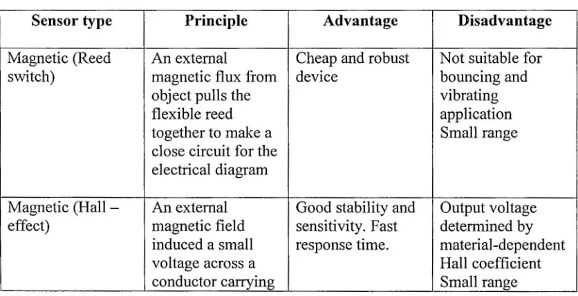
[image:16.600.60.478.531.745.2]Since the tactile sensor required direct contact between the obstacle and the robot it is always preferred as the fail-safe mode sensor in case the proximity sensors or the range sensor unable to detect the object. However, with the demand of good reliablity and durability as well as good performance proximity sensor becomes an alternative to the tactile sensor. Proximity sensor can be classified into 6 categories - magnetic, inductive, ultrasonic, microwave, optical and capacitive sensor. Table 2.1 summarises the principle of proximity sensors as well as the advantage and disadvantages of each type of the sensors.
Table 2.1 Type of proximity sensors
Sensor type Principle Advantage Disadvantage
Magnetic (Reed switch)
An external
magnetic flux from object pulls the flexible reed together to make a close circuit for the electrical diagram
Cheap and robust device
Not suitable for bouncing and vibrating application Small range
Magnetic (Hall -effect)
An external magnetic field induced a small voltage across a conductor carrying
current
Magnetic
(Magnetoresi stive)
An external magnetic field cause changing in direction of magnetization of conductive material change the
resistivity of the material
Greater range than Hall-effect and good temperature stability
Nonlinear and bistable in internal magnetization direction Small range
Inductive Current is induced
in a coil wounding around ferrite when object close to the electromagnetic field Suitable for metallic object Limited sensing range Small range
Capacitive Different dielectric
value of object give different capacitive value between the electrodes
Capable to detect metallic and non-metallic object
Sensitive to temperature and humidity
Small range
Ultrasonic Transmitter
generates ultrasonic wave and receiver detect the reflected echo and calculate time of flight to determine the range
Capable to detect liquid and solid object
Detection range depends on emitted power, reflectivity, cross-sectional area and directivity Long range
Microwave Same principle as
ultrasonic but using microwave
wavelength
Capable to determine speed using Doppler shift analysis High operating frequency distort surrounding electrical equipment Long range
Optical Reflected light
from light source is detected by
receiver -photodiode
Extendable using fibre optic cable into hazardous area
Interference from ambient light source
Newcastle University'
2.3 Sensors for Ranging
Due to limited capability of the proximity sensor distance sensor is preferred
especially for an intelligent system in an autonomous mobile robot. It provides
the information concerning the range between the robot and the obstacle. This
input is very crucial for the system in order to detect the distance of the object
before it can decide the way to prevent it. Basically distance sensor is an
enhancement of proximity sensor which also a non-contact type of sensor.
With the implementation of ranging technique the distance sensor can be
realized based on ultrasonic, microwave and optical proximity sensor. Among
ranging technique used for distance sensors are:
1. Time-of-flight
2. Triangulation
3. Frequency modulation
4. Phase-shift modulation
5. Intensity of return signal
6. Interferometry
7. Swept focus
Nevertheless not each of the technique can be applied to the sensors. For
example, the first two techniques can simply adapted to these 3 sensors which
also known as SONAR - ultrasonic sensor, RADAR - microwave sensor and
LIDAR - optical/ light sensor. Although the third and forth technique can be
implemented with radar and lidar the last three technique is adaptable only to
the lidar type of sensor. Hence the proper selection of sensor with the right
ranging technique is important which can accommodate the specification
requirement. The next topic will discuss on the selection of sensor suitable for
obstacle detection and collision avoidance application for an autonomous
2.4 Specification Requirement and Sensor Evaluation
In order to identify the suitable type of sensor to be used in the application, a specification requirement of the sensor need to be studied. This specification requirement contributes in selecting the right sensor over a wide range of sensor available. Furthermore, it also provides a guideline in term of the aspects need to be considered for each type of the sensor entirely without excluding or missing any potentially type of sensor available.
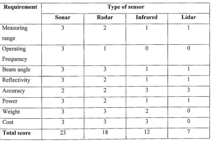
[image:19.599.57.475.391.675.2]Table 2.2 simplifies sensor evaluation with respect to the sensor specification requirement. 4 types of sensors were accessed and rated from 0 to 3. The total score in the highest value indicates the most suitable sensor for the application. Consequently it summarizes the process of sensor selection which is very complicated and confusing without a proper and systematic approach.
Table 2.2 Evaluation table of type of sensor
Requirement Type of sensor Requirement
Sonar Radar Infrared Lidar
Measuring range
3 2 1 1
Operating Frequency
3 1 0 0
Beam angle 3 3 1 1
Reflectivity 3 2 1 1
Accuracy 2 2 3 3
Power 3 2 1 1
Weight 3 3 2 0
Cost 3 3 3 0
Total score 23 18 12 7
Note:
Newcastle University'
Concerning the measuring range, sonar offers from 0.15 meter to 10.6 meter
which meets the requirement of the application. However radar provides
longer range up to 15 meter but the minimum range of 1.5 meter limits the
selection. An infrared offers maximum range of 30.5 meter whereas the
longest range offered by lidar from 1 meter minimum distance to 100 meter
maximum distance. Due to above requirement range, the infrared and lidar
were rated as a last resort.
In term of operating frequency, sonar operates within 1 kilo Hertz (kHz) to
350 kHz, followed by radar from 1 Giga Hertz (GHz) to 300 GHz. A much
higher frequency offered by both infrared and lidar is not suitable since high
frequency will affects the electrical equipment especially in the hospital or
healthcare indoor environment.
For a ring sensor that covers around the robot body, beam angle is important
as it dictates the number of sensor used for the system. Although a high
number of sensors will give accurate result, the processing time to scan all the
sensors might consume longer time thus resulting slow speed to the robot.
Both sonar and radar provide 10° to 35° beam angle whilst very narrow beam
offer by infrared and lidar range from 0.3 mili radian (mrad) to 0.5 mrad.
Another requirement need to be considered for the sensor is the reflectivity.
The reflectivity of wave depends on its wavelength as well as the frequency.
High frequency wave will penetrate object such as plastic bottle or cardboard.
Thus a low frequency suits the application since it will reflect almost all of the
objects and in this case, sonar wave reflects most of the object in comparison
with the rest sensors.
Accuracy is another element to be put into account as it governs the
performance of the sensor. Sonar offers accuracy as smallest as ± 3 centimeter
(cm) as well as radar in term of short range measurement but infrared and lidar
Regarding power consumption, sonar operates at the lowest voltage among the
three at 5 VDC. The small power requirement is crucial as it will dictates the
number of power supply such as battery pack needed. The low amount of
power consumption also contributes to longer operating hour and it is very
important especially for mobile system.
Another aspect associated with the power consumption is a weight. A
heavyweight system required more power to the motor for moving thus a very
lightweight system is far better to the system. Among those four, sonar
ranging system comes with only under 0.3 kg instead almost 1 kg weight for
both infrared and lidar.
Finally, the cost for the complete system also plays significant role. Again,
sonar offers a very cheap system in comparison with the rest of the system that
is important especially when a number of systems are required to accomplish
Newcastle University'
CHAPTER 3
3.0 LITERATURE REVIEW
3.1 B ackground of S onar
Sound Navigation and Ranging or SONAR is one of the energy available to be exploited in our environment. It is in fact an acoustical energy that operates between 20 kilo Hertz (kHz) to 200 Mega Hertz (MHz) frequencies. Figure 3.1 shows the segment of frequency range of acoustical energy. This range operates above the human hearing limit in comparison to acoustic wave which enable us to listen to the music and speaking with colleague.
Medical and Destructive Lowbass notes Animals and Chemistry
20Hz. 20KHz-+
Diagnostic ard NDE
2MHz 200MHz
[image:22.599.112.447.397.478.2]• •
Figure 3.1 Acoustical energy frequency ranges (source:
http://en. wikipedia. org/wiki/Image: Ultrasoundjange _diagram.png)
Sonar often referred as ultrasonic wave or ultrasound, unlike acoustic wave is capable to propagate in many medium such as water, air and vacuum environment. Thus it offers a wide range of application. In addition, it is easily implemented without requirement of any of transmitting medium such as wires or cables to transmit the energy.
system had never left to take the advantages of the development. Despite it
was first discovered in underwater application, sonar technology was
implemented broadly in air propagation since it perform better than in
underwater environment.
Sonar wave is generated from a transducer which receives an input from a
voltage applied to the transducer. The transducer range from 3 types;
magnetostrictive, piezoelectric and electrostatic. However, Campbell
suggested magnetostrictive type of transducer was primarily used for
high-power sonar and cleaning applications [Campbell, 1986].
Piezoelectric type of transducer changes its dimension when electrical
potential is applied to its terminal. It will start to vibrate when the electrical
potential oscillates at the crystal's resonant frequency. Campbell investigated
that even a large force is generated only a small displacement of oscillation
occurred resulting the sonar generated by piezoelectric type of transducer
propagates effectively in solid and liquid medium rather than in the air
[Campbell, 1986]. Furthermore, Everett stated mechanical inertia associated
with the vibrating crystal results latency to achieve full performance as well as
longer time to meet settling time after the voltage was removed [Everett,
1995].
In contrast, electrostatic transducer generates small forces with large
displacement amplitude thus works efficiently in the air in comparison with
the piezoelectric transducer. In addition, Campbell also stated that a
low-inertia foil membrane in the electrostatic transducer results in fast response
both in generate and degenerate of the sonar wave [Campbell, 1986].
Meanwhile, Everett claimed electrostatic transducer has a broadband of
frequency range but limited to several hundred kilohertz in contrast to
megahertz range in piezoelectric transducer [Everett, 1995].
From the findings discussed in the previous paragraph, it can conclude that
electrostatic type transducer gives quick response in comparison with
Newcastle University'
the most popular transducer in air propagation whereas the piezoelectric transducer best used in underwater environment.
3.2 Sonar Application
Sonar was first been used in an underwater application such as depth
measurement as well as deep water fish finding [Frederikson & Howard,
1974]. The application was then exploited for underwater automatic camera
focusing [Biber, etal., 1980].
However the application of sonar exploded enormously in an industrial
measurement system especially in industrial process control [Asher, 1983],
safety interlocks for dangerous machinery [Irwin & Caughman, 1985],
non-destructive testing [Campbell, 1986], liquid level measurement [Shirley,
1989], stock measurement [Shirley, 1991] and intruder detection for security
purposes [Smurlo & Everett, 1993], Medical sector also takes the benefits of
the ultrasound with sonography that provides medical imaging for woman
pregnancy.
The technology was only adapted in robotic application beginning early 80's
after a microswitch system was found inadequate for nursing robot produced
by Borenstein [Borenstein, 1985], The application of employing sonar in
mobile robot continually extended for collision avoidance [Everett, 1985;
Borenstein, 1988], position location [Dunkin, 1985; Figueroa & Mahajan,
1994] velocity measurement [Milner, 1990], map-building [Chong, 1999],
navigation [Choi, 2003; Belkhous, 2005] and wall following [Fazli, 2004],
Nevertheless, it also benefits the handicaps whose rely on wheelchair for their
mobility where the sonar provides an obstacle detection system to the
wheelchair [Sabatini, 1995; Castillo, 2006].
However, in collision avoidance system alone many had investigated the best
strategy and method to employ the sonar system in the mobile robot