E-Shaped Microstrip Patch Antenna for Ku Band
Razin Ahmed and Md. Fokhrul Islam
Department of Electrical and Electronic Engineering Islamic University of Technology
Board Bazar -1704, Gazipur, Bangladsh
ABSTRACT
Technology has been developing day by day where satellite communication has become daily part of our life. As the technological devices are getting smaller demand for multiband operating antennas are growing faster to the consumers. This paper represents an E shaped Microstrip Patch Antenna for multiband operations in Ku band. The design has been made on low cost material of FR4 substrate having dielectric constant of 4.2 with thickness of 1.6mm. The proposed scheme and probe feeding technique provide designed antenna to operate in three different frequencies range in Ku band. The antenna resonates at 12.4 GHz, 13.28 GHz, and 14.45 GHz with directivity gain of 8.6, 9.5 and 7.4 respectively. Designing and simulation of this antenna has been done by IE3D software. In this paper different types of antenna characteristics have been studied.
Keywords
Rectangular Mircostrip Patch antenna (RMPA), Mircostrip Patch antenna (MPA), Radio frequency (RF)
1.
INTRODUCTION
Rapid development in wireless communication system has been exaggerated since the birth of first radio communication system. There are many ranges of frequency band for different communication system in current time; they are allocated to services different purpose in modern life among them demand for satellite communication has been increased due to fast growth in high resolution mapping, satellite altimetry, radio astronomy service, space research service, mobile satellite service, radiolocation service (radar), and radio navigation. These applications and devices mainly operate in Ku band which is allocated in the microwave radio region of the electromagnetic spectrum. The antenna devices with single radiator that can transmit and receive multiple frequency bands become more efficient and desirable for commercial activities. Many researchers from universities and industries have introduced multiband antennas techniques passed years among them especially PIN diodes, switches and varactor diodes have been used. Main drawback of the design is they need to use a controlling turn ON/OFF switch for reconfigurable frequency operations [1, 2, & 3]. There are other antennas which can also provide multiband such as Sierpinski fractal and printed inverted F antennas but they are highly intricacy in structure [4, 5, & 6].
Micro-strip patch antennas have become popular in recent times. Compared with the conventional antenna, it has more multilateral advantages for planer profile, ability to operate in microwave frequency range, inexpensive to manufacture and especially easy to assemble in integrated circuit technology. The low profile planar configuration of Micro-strip antennas
weight, low volume and low fabrication cost, allows them to be manufactured in large quantities.
In 1950s the abstract idea of Micro-strip antenna was first introduced by G. A. Deschamps. After the evolution of the printed circuit board (PCB) technology in the 1970s, Howell and Munson developed the first practical Micro-strip antenna, which opens extensive area of research all over the world [7]. The basic structure consists of a conducting patch of any non-planar or non-planar geometry on one side of a dielectric substrate and a ground plane on other side. Ground plane provides enough reflections to the fringing fields due to the changes in length of patch antenna. Micro-strip patch antenna can be fed through different techniques among them probe feed and Micro-strip line feed are most popular and others are proximity coupled feed and aperture/slot-coupled feed. The proposed antenna serves for fixed and broadcasting satellite in frequency range of (12.2 to 12.7) GHz; Earth exploration satellite, aeronautical radio navigation and space research from (13.24 to 13.4) GHz; fixed mobile, fixed satellite (earth-to-space) and mobile satellite (earth-to-space) from (14.4 to 14.5) GHz [ 9& 10].
2.
ANTENNA DESIGNS
To design desirable E shaped MPA, first rectangular microstrip patch antenna has been constructed based on the standard designing procedure. The length and width of the antenna dimensions are determined by following equation [8].
1 2 2 r r f o W
(1) 2 1 12 1 2 1 2 1 W h r r eff
(2)
8
.
0
258
.
0
264
.
0
3
.
0
421
.
0
h
W
h
W
h
L
eff eff
(3) L f L o o eff r 2 2 1
(4)Here W is the width of the patch, vo is the speed of light in a
vacuum, εr is the dielectric constant of the substrate, fr is the
target frequency, εeff is the effective dielectric constant of the
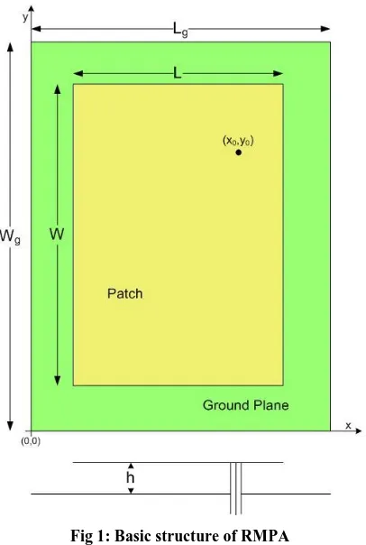
The calculated parameters are transferred to the software for simulation. RMPA has patch and ground plane dimensions of (WxL) 24mm x 17mm and (WgxLg) 34mm x 27mm
[image:2.595.329.532.68.372.2]respectively. It has been designed on FR4 substrate with dielectric constant of 4.2 and thickness of 1.6mm from the ground plane. The RMPA is excited with probe feeding technique at position of (x0, y0) = (15.6, 19.6)
Fig 1: Basic structure of RMPA
Figure 2 represent E shaped MPA with same dimensions of RMPA where two parallel slots are cutoff from rectangular patch to perturb the surface current patch and introducing local inductive effect which is responsible for multiband purpose [11 & 12]. The dimensions are given by l1 = 7mm, l2
= 10mm, w1 = 6mm, w2 = 3mm shown in Table 1
[image:2.595.67.270.164.466.2]Fig 2: Geometry of proposed antenna
Table 1. Full Dimensions for proposed antenna
Parameters Dimension (mm)
l1 7
l2 10
w1 6
w2 3
Lg 27
Wg 34
L 17
W 24
3.
RESULT AND SIMULATION
[image:2.595.310.551.418.588.2]Fig 3: Reflection coefficient (S11) of RMPA
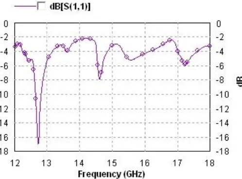
Figure 4 depicts the result of the return loss of the proposed patch antenna. It is observed that resonant frequencies appeared in range of (12-18) GHz which are 12.4 GHz, 13.28 GHz and 14.45 GHz under Ku with return loss of 16 dB,
-27.7 dB and -11.6 dB respectively. The bandwidths of resonant frequencies are typically about 235 MHz, 375 MHz, and 200 MHz respectively. The sum of bandwidths is 792 MHz which covers total 13.20% of Ku band.
.
Fig 4: Reflection coefficient (S11) of E shaped MPA
Figure 5 shows the comparison between RMPA and proposed E shaped s MPA. It is cleared that proposed antenna shows better performance in antenna characteristic. Figure 6 represents VSWR of E shaped MPA where it has been observed that the ratio of the maximum voltage of a standing wave pattern on a transmission line to the minimum voltage on the line is less than 2 at operating frequencies.
Fig 5: Reflection coefficient (S11) of E shaped MPA and
[image:3.595.55.304.75.259.2]RMPA
Fig 6: VSWR of proposed antenna
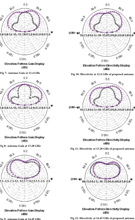
[image:3.595.310.553.330.516.2] [image:3.595.54.298.398.591.2]Fig 7: Antenna Gain at 12.4 GHz
Fig 8: Antenna Gain at 13.28 GHz
[image:4.595.68.277.69.745.2]Fig 9: Antenna Gain at 14.45 GHz
[image:4.595.322.536.76.545.2]Fig 10: Directivity at 12.4 GHz of proposed antenna
Fig 11: Directivity at 13.28 GHz of proposed antenna
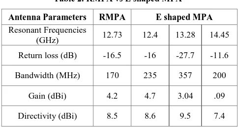
[image:4.595.324.531.300.745.2]Table 2. RMPA vs E shaped MPA
Antenna Parameters RMPA E shaped MPA
Resonant Frequencies
(GHz) 12.73 12.4 13.28 14.45 Return loss (dB) -16.5 -16 -27.7 -11.6 Bandwidth (MHz) 170 235 357 200
Gain (dBi) 4.2 4.7 3.04 .09
Directivity (dBi) 8.5 8.6 9.5 7.4
4.
CONCLUSION
A compact E shaped MPA has been presented in this paper for multiband operation in Ku band range. The proposed antenna can be used for fixed and broadcasting satellite, earth exploration satellite, aeronautical radio navigation, space research, fixed mobile, fixed satellite (earth-to-space) and mobile satellite (earth-to-space) applications. In this paper it has been observed that trimming down two parallel slots (E shape) helps to achieve multiband and have improved antenna characteristics respected to RMPA. The resonant frequencies occurred at 12.4 GHz, 13.28 GHz, and 14.45 GHz with satisfactory bandwidths and gains. The proposed antenna has maximum gain and directivity of 4.9 dBi and 10.5 dBi respectively. For further enhancements in antenna performance, new artificial man made Metamaterial can be introduced. Recently it has drawn attention to many RF engineers and researchers.
5.
REFERENCES
[1] D. Peroulis, K. Sarabandi and L. B. P. Katehi. 2005. Design of reconfigurable slot antennas. IEEE Trans. Antennas Propag., vol. 53, no.7, pp. 645-654.
[2] H. Okabe and K. Takei. 2001. Tunable antenna system for 1.9 GHz PCS handsets. IEEE Antennas Propag. Int. Symp., vol. 1, pp. 166- 169.
[3] F. Yang and Y. R. Samii. 2002. A reconfigurable patch antenna using switchable slots for circular polarization diversity. IEEE Micro. Wireless Comp. Lett., vol. 12, no. 3, pp. 96-98.
[4] C.T.P. Song, P.S. Hall, and H.G. Shiraz. May 2003. Perturbed: Sierpinski Multiband Fractal Antenna with Improved Feeding Technique. IEEE Trans. Antennas Propag., vol. 51, no. 5,, pp. 1011-1017.
[5] D.M. Nashaat, H.A. Elsadek, and H. Ghali. Aug. 2005. Single Feed Compact Quad-Band PIFA Antenna for Wireless Communication Applications. IEEE Trans. Antennas Propag., vol. 53, no. 8,, pp. 2631- 2635. [6] Paitoon Rakluea, Noppin Anantrasirichai, Kanok
Janchitrapongvej, and Toshio Wakabayashi. June 2009. Multiband Microstrip-Fed Right Angle Slot Antenna Design for Wireless Communication Systems. ETRI Journal, Volume 31, Number 3.
[7] Howell, J.Q. 1972. Microstrip Antennas, presented in International symposium on Antennas and Propagation Soc., Williamburg.
[8] Garg, R., R. Bhartia, P. Ittipiboon, A. and I. Bahl,. 1980. Microstrip Antenna Design Handbook. Artech House, Boston, London.
[9] David Lewin, Phillipa Marks and Stefano Nicoletti. 2013. Valuing the use of spectrum in the EU. London, EC4A 3BF, United Kingdom.
[10] Final Report Prepared for Ofcom. 2011. Frequency Band Review for Fixed Wireless Service. Ægis Systems Limited, 2315/FLBR/FRP/3.
[11] B.K Ang and B.K Chung. 2007. A Wideband E-shaped Microstrip patch antenna for 5-6 GHz wireless communications. Progress In Electromagnetics Research, PIER 75, pp. 397-407.