TMS320C6713 DSK Implementation of G.711
Coded VoIP Signal
Imran Ghous
Electrical Engineering Department
University of Engineering and Technology Taxila, Pakistan
Habibullah Jamal
Electrical Engineering Department
University of Engineering and Technology Taxila, Pakistan
Tahir Muhammad
Electrical Engineering Department
University of Engineering and Technology Taxila, Pakistan
ABSTRACT
The quality of speech signal over a VoIP system is degraded by various network layer problems which include jamming, jitter, packet loss. Different types of noises also degrade the quality of speech signal such as external noise and quantization noise. This paper improves the quality of VoIP speech signal affected by these noises and network layer problems. The quality of degraded VoIP speech signal coded by using ITU-T G.711 audio coding standard and implemented on the TMS320C6713 DSK has been compared with the quality of VoIP speech signal coded by using G.729 audio data compression standard which uses code-excited linear prediction speech coding (CS-ACELP) for coding purpose and is implemented on TMS320C6713 DSK. Speech Enhancement Algorithm has been proposed for the improvement in the quality of VoIP signal. In order to evaluate the performance PESQ (ITU-T P.862, Perceptual Evaluation of Speech Quality) is used.
General Terms
Speech Enhancement. Noise Removal.
Keywords
Noise Filtering, G.711, Speech Enhancement Algorithm, TMS320C6713 DSK, VoIP DSP Implementation, FIR Hanning Window Filter
1.
INTRODUCTION
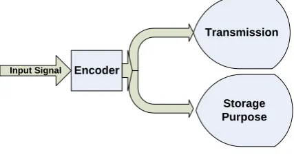
Speech Enhancement is sizzling topic in research now-a-days. Different types of coding schemes have been proposed so far for the purpose of encoding and decoding of speech signal. These techniques help in the compression and decompression of the speech signal. The part of coder which is used for the compression of speech signal is called encoder.
Encoder
Input Signal
Transmission
Storage Purpose
Fig 1: Encoder Block Diagram
The speech signal is encoded for the purpose of transmission through the channel and it can also be used for storage purpose because storage of encoded speech signal consumes less memory. The signal after transmission through the
channel is decompressed the help of decoder so that original information can be retrieved from the speech signal. The block diagram of encoder is depicted in the figure 1. Figure 2 depicts the block diagram of decoder.
Decoder
[image:1.595.60.274.595.709.2]Encoded Signal Input Output Decoded Signal
Fig 2: Decoder Block Diagram
When a speech signal is processed by the coder then a slight communication delay is observed. The functionality of speech coders is performed on the basis of the blocks of the samples. Variable delay which ranges from 1 to 500 is associated with the coders. Greater delays are associated with the digital telephony systems. On the basis of operations performed and memory locations the complexity is measured. Complexity is also associated with the problems of more power consumptions and higher delays. Due to advancement in the technology speech coders now consume less power and possess acceptable delays [1].
Coders can be generally classified into the three categories which are Source Coder, Hybrid Coder and Waveform Coder. Among all these the coders Waveform Coder has least complexity. They are independent of input and tend to reform the signal closer to the input. Quantization and Sampling are two approaches which are used by simplest coders. Pulse Code Modulation (PCM) works on this principle. Logarithmic Quantization provides the sample quality of reconstruction signal at reduced bit rate. This type of coder provides the bit rate of 64 kbps [2-3].
Differential Pulse Code Modulation (DPCM) is example of Waveform Coder. In this coder the difference between input signal and predicted signal is coded due to which bits which are required for coding are reduced. This type of coder provides the bit rate of 32 kbps. A signal is split into frequency bands when Waveform Coding is done in frequency domain and each of these individual separated frequency bands are transmitted separately [4].
Hybrid Coders are used if we want a compromise between Waveform Coder and Source Coder in term of both bit rate and how they code signal. Code Excited Linear Predictive Coder (CELP) belongs to cartoony of Hybrid Coders. This is basically analysis-by-analysis coder in which residual signal is quantized on the basis of Linear Prediction (LP). Synthesis Filter is excited by residual signal in such a way that it reduces the error and tends to match the input signal as close as possible [6].
Most well known voice codecs used now-a-days are G.711, G.729, G.722 and G.723. We shall compare the results of G.729 and G.711. G.729 Coder basically compares the original signal and locally decoded signal. The mean square error between two signals is minimized on the basis of the coder parameters. The input and output to this coder is denoted by 16-b PCM and input is band limited signal sampled at 8000 Hz. The overall algorithm of G.729 coder possesses 16 ms delay [7].
There are different coding standards used for encoding and decoding of speech signal but we have to choose the quantizer which is best according to our application. There are different types of quantizers such as pdf-optimized Quantizers, Simple Uniform Quantizers and Logarithmic Quantizers. Simple Uniform Quantizers and pdf-Optimized Quantizers are not adequate for speech signal SNR-wise. As we know that variance of speech signal varies greatly with time respect to time. These two types of quantizers are sensitive to the variance of speech signal to a greater extent but Logarithmic Quantizer SNR does not depend too much on the signal variance. The Logarithmic Quantizer is therefore a better selection for speech signals that is why we shall use G.711 quantizer. ITU-T G.711 pulse code modulation (PCM) of voice frequencies is a very popular narrow-band high-bitrate coder.
The speech signal is affected by the different types of noises such as environmental noise and quantization noise. The environmental noise may originate from the surroundings of conversation parties. The portion of original speech gets covered by this environmental noise. Similarly due to the coding noise the speech signal becomes less periodic. The speech harmonics and speech formants become less prominent after coding process. So due to the quantization noise and environmental noise the quality of our speech signal is degraded to greater extent. The process of filtering is used to reestablish the prominence of these formants.
On the basis of the Mean Opinion Score (MOS) scale the quality of decoded speech signal can be evaluated. In the MOS scale the comparison is done on the basis of another scale Perceptual Evaluation of Speech Quality (PESQ) between original and degenerated signal.
Speech Enhancement Algorithm is proposed, which uses FIR Hanning window based filter for the purpose of removal of noise through our speech signal. In which the window function is used for short time segmentation of the speech signal and then the Fast Fourier Transform (FFT) Block changes each of these short time segments into frequency domain. The noise is estimated in each of these frequency segments with the help of Voice Activity Detector (VAD) Block. Then on the basis of this estimated noise the Noise Cancellation Block removes the noise through each of these short time segments and then ultimately these short time segments are then changed to original domain and finally the enhanced signal is obtained. The Implementation of the proposed algorithm has been done on MATLAB and as well
as on the high frequency DSP processor. The Texas Instruments (TIs) TMS320C6713 DSK has been used as the high frequency DSP processor. The PESQ is used to evaluate the performance of our resultant speech signal [8-10]. The remaining of this paper is organized as follows. The section II discusses proposed architecture detail in order to efficiently implement and understand the proposed algorithm. The III section shows the comparison of results and IV section shows the conclusion and finally the future work is proposed in the final section.
2.
PROPOSED ARCHITECTURE
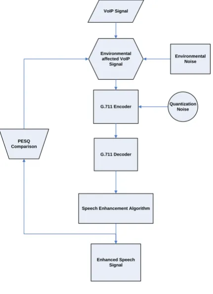
The speech signal is taken as an input from [11]. The external noise gets added into input VoIP signal. Using G.711 encoder the resultant noisy speech signal is encoded in VoIP frames. The G711 Codec block is a Logarithmic Scalar Quantizer designed for narrowband speech. Narrowband speech is defined as a voice signal with an analog bandwidth of 4 kHz and a Nyquist sampling frequency of 8 kHz. This block quantizes a narrowband speech input signal so that it can be transmitted using only 8-bits. The G.711 Codec block has three modes of operation: encoding, decoding, and conversion. The network configurations were inserted into VoIP frames by using simple Gilbert model. If there is an “Error” state then in that case a VoIP packet is dropped otherwise it is retained. The resulting stream of frames that are available at the G.711 encoder output are then decoded using G.711 decoder and then the resultant decoded signal is filtered for the noise using Speech Enhancement Algorithm.
VoIP Signal
Environmental affected VoIP
Signal
G.711 Encoder
G.711 Decoder
Enhanced Speech Signal
Environmental Noise
Quantization Noise
Speech Enhancement Algorithm PESQ
[image:2.595.322.538.384.681.2]Comparison
Fig 3: Proposed Architecture
Figure 3 shows the proposed architecture of the given algorithm.
and the A-law algorithm encodes 13-bit signed linear PCM samples to 8-bit Logarithmic scale. We shall use µ-law algorithm in our proposed architecture.μ-law encoding takes a 14-bit signed linear audio sample as input, increases the magnitude by 32 (binary 100000).
G.711Coded Signal
Buffering and Windowing
FFT
Noise Cancellation Block
Bias Removal
Half Wave Rectification
Rseidual Noise Reduction
IFFT
Add and Overlap
Enhanced Output Siganl
[image:3.595.129.206.129.423.2]VAD
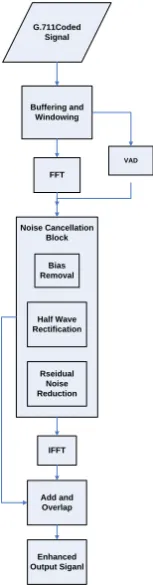
Fig 4: Speech Enhancement Algorithm
Digital Filtering Algorithm block is consisted of various sub-blocks.
I. Windowing
II. Voice Activity Detector (VAD) III. Noise Cancellation Block IV. Add and Overlap
Figure 4 shows the block diagram of Speech Enhancement Algorithm. Input is noisy signal whose samples after passing through Data Buffering and Windowing block are sent to Voice Activity Detection (VAD) Block [12].
The first Stage in VAD is noise reduction stage and on the basis of the classification rule the speech and non-speech signals are estimated in VAD. Feedback in VAD improves the performance in case of non-stationary noisy signals and then noise cancellation block estimates the remaining noise in the input signal and then removes it. After that Add and Overlap Block reorders the multidimensional input signals and ultimately enhanced signal is obtained.
2.1
Windowing
In windowing we take the smaller subset of the larger data for the purpose of the analysis and processing. Rectangular window is a naive example of the windowing this involves truncating the data before and after the window. Window based filter design method is used to improve the quality of the degraded VoIP signal because these types of filters are inherently stable , have linear phase, great flexibility in shaping the magnitude response and are easy to implement.
Z domain is used to represent the transfer function of the FIR filters. This is also called all-zero filter because the zeros in z-plane help in finding frequency response magnitude characteristics. The N-point FIR filter in z domain is given by
(1)
The frequency response corresponding to the unit impulse response in window based method can be found by following equations
(2)
(3)
The above relation gives the value of in infinite duration. So this infinite duration needed to be cut short to a point in order to yield the FIR filter of length M. This finite limitation of to length has the same effect as we multiply to rectangular window. The rectangular is defined as
(4)
So as the result of multiplying the unit sample response
of the desired FIR filter is
(5)
(6)
The value of for Hanning window is given by following equation
(7)
Window based FIR filtering is more simple, beneficial and fruitful as compared to other filtering methods and these are easy to use. The main reason beyond preferring this type of filtering methods is that these methods possess the set of well defined equation for the computation of the window coefficients. The proposed FIR filter is designed in MATLAB SIMULINK.
2.2
Voice Activity Detector (VAD)
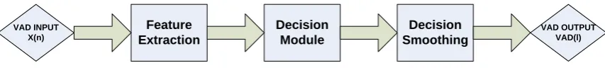
The presence of the speech contents in the noisy signal are taken into consideration by VAD. On the basis of feature vector the decision of VAD is made. An assumption is taken into consideration that the speech signal and the noisy signal can be added. Thus the module of VAD has to work in favor of two hypotheses
(8)
[image:3.595.375.505.208.280.2]Feature Extraction Decision Module Decision Smoothing VAD INPUT X(n) VAD OUTPUT VAD(l)
Fig 5: Voice Activity Detector
2.2.1
Feature extraction
We have to select discriminative features for the purpose of detection on the basis of feature extraction block works. There are different types of the speech features on the basis of which detection can be made such as sub-band and full-band energies, measurement of divergence of the spectrum between the background noise and the speech, zero crossing rates of the pitch and high-order statistics. Current frame observation method is used by most of the VAD and they do not consider contextual information. For the significant detection of the speech in the noisy environment the long-term speech information may be used.
2.2.2
Formulation of the Decision Rule
There are different types of algorithms of the VAD which are given as
a. Statistical Likelihood Ratio Test (LRT) b. Long-term spectral divergence
c. Multiple observation likelihood ratio test d. Order statistics filters
We shall discuss Long-term spectral divergence algorithm for the detection of the voice activity. This algorithm assumes that the most significant information for the detection of the voice activity lies in the time-varying signal spectrum magnitude. Instead of using the instantaneous values of the spectrum this method takes a long-term speech window. Then on the basis of Long-Term Spectral Divergence (LTSD) the decision is formulated.
Suppose we have segmented a noisy speech signal into the overlapped frames and is its amplitude spectrum for the K-th band at frame . The Long-Term Spectral Envelope (LTSE) of N-order can be defined as
(9)
The decision rule of VAD can be found by means of N-order LTSD between the noise speech and that can defined as the derivation of the LTSE with respect to that of average noise spectrum magnitude for that of band, k=0,1,……,NFFT-1 and is given by:
(10)
2.2.3
Decision Smoothing
The VADs which use frame by frame basis in order to from the decision rule they use decision smoothing algorithms so that they can improve robustness against the noise. In the speech signal processes and the less signal energies of the word endings and beginnings the motivation for these approaches can be found. VAD decision is smoothened by so called hang-over algorithms so that the speech periods which are masked by acoustic noise can be recovered.
VAD block in the figure 5 basically detects the noise that is present in our speech signal. The noise is basically detected on the basis of the LTSD between noise and speech. On the basis of this decision rule the noise is estimated by this block
and ultimately this noise can then be removed by the noise cancellation block.
2.3
Noise Cancellation Block
The noise cancellation block consists of the three sub-blocks which are given as
(a) Bias Removal
(b) Half Wave Rectification (c) Residual Noise Reduction
2.3.1
Bias Removal
This block removes the signal bias from the transmitted signal. As the speech signal travels through the transmission channel the unknown adverse affects contaminate the quality of the speech signal so, this removes these adverse affects through the signal [13].
Basically when a speech signal travels through the transmission channel it encounters the some unknown variable conditions which deteriorate the quality of our speech signal. These unknown variable conditions came into being due to the channel interference, ambient noise, articulatory effects and various sound pick-up equipments [14].
The noise is generally considered additive to the speech signal. The real noise spectrum is not generally the flat so this will result in the degradation and the speech may not be well recognized.
Speech reorganization is also very well affected by the channel interference. Suppose if we consider the case of the telephone channel, a signal between the 200 Hz and 3200 Hz is transmitted by the band pass filter through the telephone channel with different attenuation across the different spectral bands. Due to this severe quality of the speech signal may be obtained.
The bias removal block is used for the removing the effects the interference and ambient noise while the signal is passing through the channel. This block has two inputs one is from the VAD block and another input is from output of the FFT block whose magnitude is used as the input to this block. Bias Removal block takes the noise average on the basis of the output of the noise VAD block. Then with the help of the embedded function the input noise and the average noise are minimized. This block yields two outputs one is average noise output and other is minimized noise output.
2.3.2
Half Wave Rectification
Half Wave Rectification block then further removes the noise from the output of the Bias removal block. The average noise output that is used as an input in this block is further reduced in comparison with that of the minimized noise value. Thus the minimized noise output and the average noise are then added in this block and yield the output. The output of this block still possesses some residual noise which is then further reduced by the residual noise reduction block.
2.3.3
Residual Noise Reduction Block
value of the noise and the other input is from the output of the Half Wave Rectification block which is basically a minimized noise then with the help of the Embedded MATLAB function block we assign to each maximum value of the noise the minimized noise value in this way the noise is reduced from the speech signal and the quality of the signal is improved with the help of the this noise removal scheme. Then the IFFT block changes the speech signal back to original time domain. As Hanning Window based FIR filter is used for the
windowing. We have used the buffer overlap function for the continuous formation of the window function now at the end the effect of that buffer overlap block can be removed with the help of Add and Overlap Block which ultimately converts our signal into the original form. Enhanced signal is obtained then we can compare the quality of the speech signal with PESQ.
[image:5.595.57.539.155.612.2]2.4
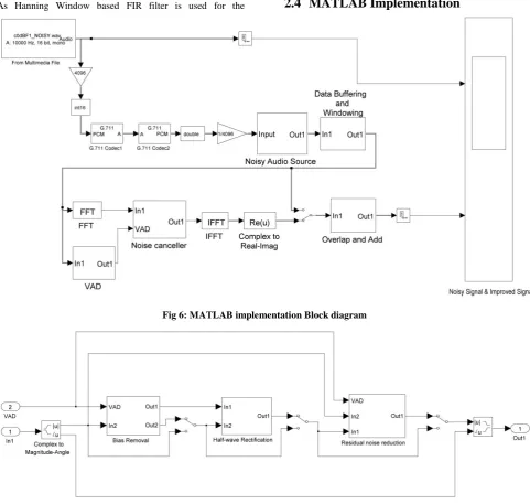
MATLAB Implementation
Fig 6: MATLAB implementation Block diagram
Fig 7: Noise Cancellation Block
MATLAB implementation is shown in the above figure 6 which shows that noisy input signal is read from the .wav file with the help of the From Multimedia File Block. After that the input noisy signal goes in two ways. In first path it goes directly to the scope in the second path after passing through several stages it ultimately reaches the scope and both input noisy signal and the output enhanced signal are then compared in the scope.
The input noisy signal is then given as input to the G.711 PCM encoder which uses the µ-law encoding algorithm for the encoding of the input noisy signal. The µ-law encoding algorithm changes the 14-bit input signal to the 8-bit
compressed signal so that this signal could be used for the purpose of the transmission and the storage. After the encoding the µ-law decoding algorithm changes signal back to the original form but during process the quantization noise will affect the quality of the output decoded signal.
block changes these Short time segments into the frequency domain then noise is estimated in each of the these frequency segments with the help of VAD. The VAD block uses the LTSD for the formulation of its decision rule. LTSD is computed between the noise and the speech on the basis of which the noise is identified. After that the speech signal is passed through the Noise Cancellation Block which is shown in the figure 7. This first stage of the noise cancellation block is called Bias Removal block which cancels the effects of the interference and the ambient noise which are introduced in the speech signal during its transmission through the channel. This block estimates the average noise and then input noise and the average noise are minimized. After that Half Wave rectification block cancels the remaining noise through the output of the Bias Removal Block. The average noise and the minimized noise are further minimized in this block. Then in the last stage the residual noise from our signal is reduced with the help of the Residual noise Reduction block.
This block has three inputs one input is from the VAD which selects the maximum value of the noise then the second input is minimized noise output which is obtained from the Half Wave Rectification block. With the help of the embedded MATLAB function we assign the minimum value of the noise to the maximum value of the noise in this way noise is reduced from our output enhanced signal. Then the IFFT block changes our signal back to the time domain. As at this stage the noise has been reduced from by the short-time segmentation and by noise removal techniques through each of these segments. Then at the end the add and overlap block removes the effect of the buffer overlap block which is used during windowing so that our window function should work properly without skipping any values.
Add and Overlap Block cancels this effect and converts the output signal back into its original form in which it was before windowing process. Then the un-buffer block is used in both the cases before the scope. This block produces the frame based output which can be used by scope for the displaying of the input data this block basically changes the M by N inputs into the 1 by N outputs so that each row of the input matrix should be treated as the independent time sample at the output side. Then ultimately the each of these independent signals is displayed in the scope in the time domain.
2.5
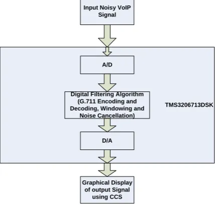
TMS320C6713 DSK Implementation
The figure 8 depicts the TMS320C6713 DSK implementation of VoIP using G.711 audio companding standard. In the beginning the noisy VoIP signal is used as an input and then with the help of the A/D conversation block this noisy analog input signal is changed into the digital domain for the purpose of processing. After the input noisy has been changed into the digital domain G.711 encoder compresses the digital domain signal. The G.711 encoder uses the µ-law data compression algorithm for the purpose of the compression of the input data. The µ-law data compression algorithm basically changes the 14-bit input signal into the 8-bit signal. Then after the data has been compressed to 8-bit bits the G.711 decoder changes the data back to the original form so that it can be read. As this resultant decoded signal is affected by the quantization noise and the external noise so for the improvement in the quality of the signal this noise must be removed from the resultant decoded signal for that purpose speech enhancement algorithm plays it part. This algorithm is consisted of the windowing and the noise cancellation section. The windowing
block is used for the short time segmentation of the speech signal then the with help of the FFT we change those short time segments into the frequency domain and then noise is estimate through each of those frequency segments with the help of the noise activity detector. Then after the noise has been estimated through each of these frequency segments the noise cancellation section is then use for the removal of the noise from each of these frequency segments with the help of the its sub-sections.
Input Noisy VoIP Signal
TMS3206713DSK A/D
Digital Filtering Algorithm (G.711 Encoding and Decoding, Windowing and
Noise Cancellation)
D/A
Graphical Display of output Signal
[image:6.595.321.536.188.393.2]using CCS
Fig 8: TMS320C6713 DSK Implementation Block Diagram
There are three sub-sections in the noise cancellation block. One is bias removal section that is used for the removal of the bias from through these frequency segments. The bias problem is introduced into the speech signal as it travels through the transmission channel. This problem is due to effects of the interference and the ambient noise during its traveling through the transmission channel. After that two other blocks remove the remaining noise from our speech signal and at the end ultimately enhanced speech signal is obtained.
3.
COMPARISON OF RESULTS
By analyzing the spectrum of both input noisy signal and output enhanced signal we can observe that the filter is designed in such a way that it efficiently improves the quality of the input noisy signal. The first 1024 samples of output enhanced signal are depicted by TMS320C6713 DSK plots. Figure 13 shows the plot of the single time TMSC6713 DSK implementation of output enhanced signal and similarly FFT magnitude plot signal can be observed in figure 14. Complex FFT of output enhanced signal is shown in figure 15.
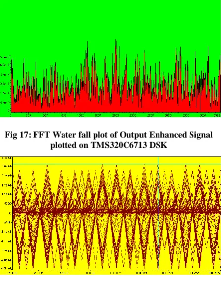
The Phase and Magnitude plot of output enhanced signal can be seen in the figure 16. Similarly Water fall analysis of output enhanced signal is depicted in the figure 17. Ultimately the eye diagram of output enhanced signal can be seen into figure 18.
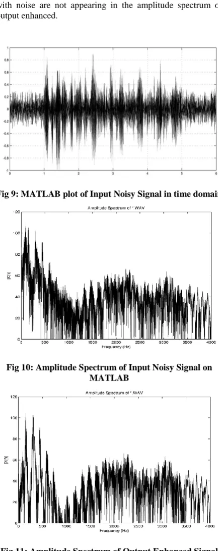
enhanced signal. Both these figures can be distinguished easily we can see enhanced signal is clean from the noise. Similarly if we compare the Amplitude spectrum of both signals which is depicted in the figures 11 and figure 10. We can see that frequency components which were associated with noise are not appearing in the amplitude spectrum of output enhanced.
[image:7.595.58.275.124.671.2]Fig 9: MATLAB plot of Input Noisy Signal in time domain
Fig 10: Amplitude Spectrum of Input Noisy Signal on MATLAB
Fig 11: Amplitude Spectrum of Output Enhanced Signal on MATLAB
Fig 12: MATLAB plot of Output Enhanced Signal in time domain
[image:7.595.60.277.173.329.2]Fig 13: Single time Output Enhanced Signal plotted on TMS320C6713 DSK
Fig 14: FFT Magnitude plot of Output Enhanced Signal plotted on TMS320C6713 DSK
[image:7.595.318.542.252.381.2] [image:7.595.316.546.413.536.2]Fig 15: Complex FFT plot of Output Enhanced Signal Plotted on TMS320C6713 DSK
[image:8.595.315.543.73.217.2]Fig 16: FFT Phase and Magnitude plot of Output Enhanced Signal plotted on TMS320C6713 DSK
Fig 17: FFT Water fall plot of Output Enhanced Signal plotted on TMS320C6713 DSK
Fig 18: Eye Diagram plot of Output Enhanced Plotted on TMS320 C6713 DSK
Fig 19: PESQ Comparison
4.
CONCLUSION
Speech quality of VoIP system is degraded due different network layer problems such as packet loss delay and jitter and external noise. Different noise filtering algorithms have been proposed so far for the removal of noise form speech signal. This paper compares the quality of speech signal that is implemented on digital signal processor using G.729 audio data compression algorithm with the ITU-T G.711 PCM coder implemented using digital filtering algorithm on high frequency DSP processor. PESQ (ITU-T P.862, Perceptual Evaluation of Speech Quality) is used to evaluate the performance. PESQ value of the speech signal implemented using previous technique was 2.4 but the PESQ value of the enhanced signal have been improved to 2.5507 by the our proposed architecture, which shows that our proposed architecture has better performance than that of previous one [14].
5.
FUTURE WORK
In Future this Algorithm can be modified for G.711.1 Implementation and the results can be compared with these algorithms.
6.
REFERENCES
[1] D. Collins, Carrier Grade Voice Over IP. San Francisco: McGraw-Hill, 2001.
[2] N. Katugampala and A. Kondoz, "A hybrid coder based on a new phase model for synchronization between harmonic and waveform coded segments," in Acoustics, Speech, and Signal Processing, 2001. Proceedings. (ICASSP '01). 2001 IEEE International Conference on, 2001, pp. 685-688 vol.2.
[3] G. H. Hakonsen and T. A. Ramstad, "On Losses of Performance in a Joint Source Channel Coder," in Signal Processing Symposium, 2006. NORSIG 2006. Proceedings of the 7th Nordic, 2006, pp. 278-281. [4] J. C. Bellamy. (2000). Digital Telephony.
[5] T. Painter and A. Spanias, "Perceptual coding of digital audio," Proceedings of the IEEE, vol. 88, pp. 451-515, 2000.
[6] S. M. Tsai and J. F. Yang, "Efficient algebraic code-excited linear predictive codebook search," Vision, Image and Signal Processing, IEE Proceedings -, vol. 153, pp. 761-768, 2006.
[image:8.595.56.283.390.678.2]VoIP: G.711 VS G.722 Based on Interview Tests with Thai Users," MECS, vol. 4, pp. 19-25, March 2012. [8] T. Daengsi, et al., "A study of VoIP quality evaluation:
User perception of voice quality from G.729, G.711 and G.722," in Consumer Communications and Networking Conference (CCNC), 2012 IEEE, 2012, pp. 342-345. [9] ITU-T Recommendation P.862," Perceptual evaluation
of speech quality (PESQ), an objective method for end to end speech quality assessment of narrow band telephone networks and speech codecs, " Feb. 2001.
[10]Harjit Pal Singh, Sarabjeet Singh and Jasvir Singh. Comparison of Narrowband and Wideband VoIP using TMS320C6713 DSP Processor. IJCA Proceedings on International Symposium on Devices MEMS, Intelligent Systems & Communication (ISDMISC) (6):25-29, 2011. Published by Foundation of Computer Science, New York, USA
[11]http://www.voiptroubleshooter.com/open_speech/. Open Speech Repository.
[12]A. Sangwan, et al., "VAD techniques for real-time speech transmission on the Internet," in High Speed Networks and Multimedia Communications 5th IEEE International Conference on, 2002, pp. 46-50
[13]Z. Tufekci, "Convolutional Bias Removal Based on Normalizing the Filterbank Spectral Magnitude," Signal Processing Letters, IEEE, vol. 14, pp. 485-488, 2007. [14] M. G. Rahim and J. Biing-Hwang, "Signal bias removal
for robust telephone based speech recognition in adverse environments," in Acoustics, Speech, and Signal Processing, 1994. ICASSP-94., 1994 IEEE International Conference on, 1994, pp. I/445-I/448 vol.1