Digital' s Networks:
An Architecture With A Future
Digital Equiprnent Corporation makes no representation that the interconnec-tion of its products in the manner described herein will not infringe on existing or future patent rights, nor do the descriptions contained herein imply the granting of liccnse to make, use, or sell cquipment constructed in accordance with this description.
The information in this book is subject to change without notice and should not be construed as a commitment by Digital Equipment Corporation. Digital Equiprnent Corporation assumes no responsibility for any errors that may appear in this document.
The following are trademarks of Digital Equipment Corporation: ALL-IN-ONE, DEC, DEcnet, DEcsystem-20, DECUS, the Digital logo, Micro/Rsx, MicrovAx I, Observer, PACKETNET, PDP, Professional, RSTS/E, RSX, Tops-20, UNIBUS, VAX, and VT100.
Table of Contents
Preface . . . .. VII
CHAPTER 1 . Introducing and Defining DECnet
andDNA... 1
What is DEC net ? . . . .. 1
Uses of a DEcnet Network. . . .. 4
Digital Network Architecture . . . 5
In terfaces . . . .. 6
Protocols. . . .. 10
Importance of a Network Architecture . . . 13
DEC net Capabilities . . . .. 14
Topology Alternatives . . . 16
DEC net Phases .... . . .. 19
CHAPTER 2 . DECnet Concepts. . . .. 21
Nodes . . . 21
Lines and Circuits . . . " . . . 24
Transmission Modes ... . . . .. 26
Data Link Protocols. . . .. 27
DDCMP Fuctional Description . . . .. 28
DDCMP Messages . . . .. 31
Data Messages. . . .. 31
Control Messages . . . 32
Maintenance Messages . . . 34
DDCMP Operation .. . . .. 34
Typical Message Exchange . . . 35
Maintenance Mode . . . 37
Ethernet Functional Description . . . 37
Ethernet Messages. . . . .. 41
Ethernet Operation . . . 44
Routing . . . 47
Routing Terms . . . .. 49
Routing Algorithms and Databases . . . 52
Routing Features . . . 53
II
Routing Messages. . . . .. 56
Routing Operation . . . .. 59
Data Flow . . . '. 64
Data Flow at the Source Node ... ' ... 66
Data Flow Across the Network to the Destination Node .... 68
Data Flow at the Destination Node ... . . .. 69
CHAPTER 3 . DECnet Configurations . ... " 71 DEcnet Environments . . . .. 72
Wide Area Networks . . . 72
Local Area Networks . . . 74
N ode Characteristics. . . .. 81
Phase III and Phase IV Nodes. . . .. 82
Routing Capabilities . . . 82
General Purpose and Dedicated Nodes ... " 84 Line and Circuit Characteristics . . . 88
The Total Picture . . . " 89 CHAPTER 4 . Common MechanislDs in DECnet Functions. . . .. 92
Logical Links . . . " 92 When Are Logical Links Required? ... 93
How to Create a Logical Link . . . 94
Behind the SceneS-DEcnet Software and Logical Links .. " 95 End-to-End Communication Layer and NSP . . . • • . . . . " 95 Session Control Layer . . . ; . .. 99
Requesting a Connection . . . 101
Receiving a Connect Request . . . 101
Session Control Messages . . . 103
How the Program Identifies Logical Links ... 103
Multiple Logical Links \Vithin a Program ... 104
Data Types Within a Logical Link . . . 105
Segmentation and Reassembly of Data ... 105
III
Flow Control . . . 108
Access Control . . . 109
User Transparency . . . 111
CHAPTER 5 . Task-to-Task COlnmunications ... 112
OEcnet Task-to-Task Calls . . . 112
Requesting a Logical Link . . . 113
Object Types and Names . . . 116
Accepting/Rejecting a Logical Link Request ... 117
Sending and Receiving Data . . . 119
Terminating the Link . . . 121
CHAPTER 6· Remote File and Record Access ... 122
The Data Access Protocol (OAP) Interface ... 123
Programming Remote File Access . . . 126
File System Capabilities . . . 128
Initiating Remote Access . . . 130
The File Specification . . . 131
Access-Control Information . . . 131
File Characteristics . . . 132
Accessing Remote Files From a Terminal ... 133
Access Control . . . 134
File Protection . . . 134
Remote File Specifications . . . 135
Remote Command File Submission ... 135
CHAPTER 7 . Network Terminal Facilities ... 136
Interactive Terminal-to-Terminal Communcations ... 136
Network Virtual Terminal Facilities ... 138
Network Virtual Terminal . . . 139
Network Virtual Terminal Operation ... 146
Local Area Transport (LAT) Protocol ... 148
IV
CHAPTER 8 . Internetwork Conununications ... 151
X.25 Communicatons ... 151
DTES and DCES . . . 153
X.25 Circuits ... 153
X.25 Gateway Access Protocol ... 155
X.25 Gateway Access Modules ... 157
X.25 Access Methods ... 165
CCITT Recommendations for X.3, X.28, and X.29 ... 168
DEcnet/ SNA Communications . . . 169
DEcnet/ SNA Gateway Access Functions . . . 170
DEcnet/sNA Gateway Access Modules . . . 173
DEcnet/sNA Circuits . . . 177
Loading the Gateway Node Software . . . 178
CHAPTER 9 . How DECnet Supports Applications .. 179
DEcnet's Task-to-Task Capability in an Application Environment . . . 181
Task-to-Task Communication: Order Entry and Production Scheduling . . . 182
Network and Application Interaction . . . 183
DEcnet's File Transfer Capability in an Application Environment . . . 185
U ser-Initiated File Transfer: Market Research and Sales Analysis . . . 185
Program-Initiated File Transfer: Quality Control and Vendor Analysis . . . 188
DEcnet's Remote File Access Capability in an Application Environment . . . 189
Network Virtual Terminals. . . ... 189
Short-Term Cash Management . . . 190
DEcnet's Terminal Facilities in an Application Environment .191 Order Entry and Production Scheduling . . . 192
Market Research . . . , ... 193
Short-Term Cash Management . . . 194
v
CHAPTER 10· Network System Management ... . 198
Network Management Utilities . . . 199
Network Management Messages . . . 201
Planning for Node Generation . . . 205
Generating Network Software . . . 208
Defining Configuration and Other Static Parameters ... 209
N ode Addresses and Names . . . 209
N ode Verification Passwords . . . 209
Network Object Parameters . . . 210
Routing Parameters . . . 211
Line Identification . . . 212
Circuit Parameters . . . 212
Transmission Mode . . . 216
Operating a Node . . . 216
Controlling the State of a Node . . . 216
Controlling Line or Circuit State . . . 217
Monitoring Node Activity . . . 218
Downline Loading . . . 220
Downline-Loading Definitions . . . 221
Downline-Loading Database Parameters ... 221
Performing a Downline Load . . . 222
Downline-Loading and Checkpointing RSX-IIS Tasks ... 224
CHAPTER 11 . Monitoring and Testing DECnet Performance . . . 228
Integrated Testing Tools . . . 229
Loopback Testing . . . 229
Upline Dump . . . 237
Monitoring Network Operation with Observer ... 250
Glossary . . . 256
VII
PREFACE
Distributed data processing is a computing philosophy Digital introduced and popularized. For over 20 years, Digital has been developing products that bring computing power right into people's work areas, whether these be offices, labs, or factory floors. Digital has made it possible for people to use computing resources from terminals on their desks, rather than depend on a computer in an isolated room. The corporation's wide range of communications products testifies to its commitment to bringing computing power to user locations, where the resources are most needed.
Introduction to DECnet and the Digital Network Architecture (DNA)
discusses DNA-the model of structure and function upon which Digital's communications products are based-and the various implementations of DEcnet-Digital's family of networking soft-ware. This handbook introduces readers to the capabilities of the following new products:
• DEcnet-vAX
• DEcnet-RsX (Rsx-llM,RSX-llM-PLUS, and Rsx-lls) • DEcnet-20
· DEcnet-10
VIII
The handbook introduces readers to the following new Phase IV concepts and products:
• PRo/DEcnet
• Ethernet and related hardware
• DEcnet/sNA Gateway (for VAX/VMS and Rsx-ll systems) • DEC net Terminal Server
• DEC net Router Server
• DEC net Router/x.25 Gateway • Observer
Introduction to DECnet and the Digital Network Architecture (DNA)
describes the concepts and capabilities of DEcnet networks. A
DEC net network consists of two or more Digital computer systems, enhanced with DEcnet software and linked by physical channels or communication lines. Systems in a DEcnet network can communicate with each other and share resources. Products are also available that enable DEC net systems to communicate with other network entities, such as IBM SNA mainframes and packet-switched data networks (PSDNS). DEcnet networks can be local area or wide area configurations or configurations that include wide area and local area networks.
All implementations of DEcnet (DEcnet VAX, PRo/DEcnet, and DEcnet-Rsx, for example) embody the same network concepts. The specific capabilities of a DEcnet network depend on the type of system participating in the network and on the network's applica-tion. The objectives of this handbook are:
• To describe the common DNA network concepts behind all imple-mentations of DEC net
IX
One of the primary aspects of a DEC net network is the peer relationship among its systems. Network operation is efficient, since any system in the network can initiate and accept communi-cations without the services of a controlling system. This hand-book describes the relative ease and speed with which network users can access the resources of any system in a peer-oriented network.
This handbook is intended for readers with a knowledge of communications technology who want to understand the DNA structure and who want to learn about the concepts and capabili-ties of DEC net systems. It assumes that the reader is familiar with Digital operating system concepts, but not with DEcnet. Typical readers will include the personnel at the site of a newly installed DEcnet system who can read this manual to learn about the kind of work DEC net enables them to perform. Another group of readers will include system managers and designers who are thinking about using DEcnet to expand the capabilities of their existing Digital computer systems. And, finally, the handbook is also intended for system managers and designers who do not yet use Digital systems but who are considering the implementation of a computer network.
Introduction to DECnet and the Digital Network Architecture (DNA)
consists of three parts, encompassing eleven chapters:
• The first part, Chapters 1 to 4, introduces DEcnet concepts and general configuration guidelines for DEcnet networks .
x
Chapter 1· Introducing
and Defining DECnet and DNA
This handbook introduces readers to the Digital Network
Architec-ture (DNA)-the framework of specifications within which Digital
designs its communications products-and to DECnet-the family of networking products that Digital has implemented in accord-ance with DNA specifications. Readers will learn how and where DEC net is used and what capabilities it offers. In addition, they will understand the importance of a network architecture such as DNA.
There are several implementations of DEcnet, one for each operat-ing system from Digital. This handbook discusses features and capabilities that are common to all DEcnet implementations. For details on specific implementations, refer to the documentation accompanying the implementations .
. What is DECnet?
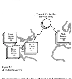
DEcnet is a family of software and hardware communications products that enables Digital operating systems to participate in a network environment. A network is an entity of two or more computer systems that are connected by physical links (cable, microwave, or satellite, for example) for the purpose of exchang-ing data and sharexchang-ing resources. Every system in the network is called a node. Figure 1.1 illustrates an example of a DEC net network.
This handbook refers to two types of network users:
2· Introducing and Defining DECnet and DNA
Figure 1.1
A DECnet Network
Transmit Via Satellite (Physical Link)
3
DEC net permits great flexibility in configuring a network. A DEcnet network can start with two nodes and be expanded to include over 64,000 nodes. Network managers can configure a local area network, with nodes located in a building or spanning a cluster of buildings, and expand the configuration to a wide area network, with nodes distributed in different cities across the country and even in different countries. Optionally, very large DEC net net-works (with over 1,023 nodes) can be configured as interrelated groups of nodes or" areas." DEC net can support up to 63 areas with up to 1,023 nodes in each area. Area-based networks are particu-larly effective in large organizations; each department can have a separate area in a corporate-wide network.
The nodes in a DEcnet network can run any of Digital's many operating systems. A DEcnet network can comprise any combina-tion of VAX systems running VAX/VMS; MicrovAx I systems running MicrovMs or VAXELN; PDP-ll systems running Rsx-llM, Rsx-lls, Rsx-llM-PLUS, RSTS/E, or RT-ll; DECSYSTEM-20s and DEcsystem-10s running Tops-20 and Tops-10 respectively; and the Professional 350 personal computers running the p/os operating system.
4· Introducing and Defining DECnet and DNA
Decentralization also provides a great deal of flexibility in the way networks can be configured. Chapter 3 describes the type of configurations possible in a decentralized network .
. Uses ofa DECnet Network
It is DEC net that enables various Digital systems in an organiza-tion, which are fulfilling differing application requirements, to communicate among themselves. It lets them exchange data and share resources, thereby enabling the implementation of all effi-cient data processing ~peration.
Networked systems can share expensive resources such as laser printers and mass storage devices. Costly peripherals, therefore, don't have to be duplicated.
Systems in a network can exchange information so that fewer copies of a given file can be maintained. That way, users can be assured that they are accessing the most current version of a file. In addition, a network can speed up information flow within an organization, since file transfers between systems are rapid.
In a network, data that has been entered interactively at a personal computer can be sent to update a database on a large system. The resources of the large system are not tied up in interactive data entry and are available for complex tasks requiring extensive cpu
power.
5
From their terminals, network users have access to a wide expanse of resources. They can access the computing power or data resources of any node on their DEcnet network. They can also access the resources of non-Digital systems on other networks. DEC net supports gateways that enable Digital systems to commu-nicate with systems from other vendors. The DEcnetl SNA Gate-way enables nodes in a DEcnet environment to communicate with systems in an IBM System Network Architecture (SNA) environ-ment. The DEcnet Router/x.25 Gateway enables DEcnet nodes to communicate with Digital and non-Digital systems implement-ing the x.25 protocol and connected to packet-switched data networks (PSDNS). See Chapter 8 for further explanation of communication with foreign-vendor networks.
The gateways enable organizations to maintain vendor indepen-dence and take advantage of the capabilities of systems from different manufacturers. At the same time, networks make it possible for the different systems in an organization to exchange information and share resources.
Gateways offload communication functions like routing and protocol translation from network nodes, freeing up the latter to process user applications with greater efficiency. See Chapter 3 for further details .
. Digital Network Architecture
6· Introducing and Defining DECnet and DNA
Architecture Layers
ISO DNA
User Application
Network Management
Presentation Network
Application
Session Session Control
Transport End-to-End
Communication
Network Routing
Data Link Data Link
Physical Link Physical Link
Figure 1.2A
ISO
and
DNAModels
DNA includes the specifications that govern the interrelationship of the various software components making up DEcnet. There are two kinds of intercomponent relationship that DNA defines: interfaces and protocols.
Interfaces
[image:19.366.35.319.61.341.2]7
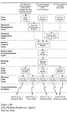
boundaries are structured as a hierarchical set of layers (shown in Figure 1.2A). DEC net software is arranged, according to function, as modules within these layers (see Figure 1.2B). DNA layers, from highest to lowest, are:
User Layer-The user layer encompasses user-written programs and user-level services that access the network, network services that directly support user and application tasks, and overall system management. The most common services accessed by users at this level include resource sharing, file transfers, remote file access, database management, and network management. All are described in greater detail in subsequent chapters.
Network Management Layer-The Network Management layer defines the functions used by operators and network managers to plan, control, and maintain DEC net networks. This layer interfaces with all the DNA layers below it to gather data on network performance and change network operational parameters. Func-tions include downline loading of remote nodes and loopback network line testing. Chapters 10 and 11 discuss network manage-ment in greater detail.
8 • Introducing and Defining DECnet and DNA User Layer Network Management Layer Network Application Layer Session Control Layer End-to-End Communication Layer Routing Layer Data Link Layer Physical Link Layer Communications Facilities The Network Control Program, which allows manager/operator to monitor/control network activity
CD A user program communicating with a remote program Network Management Routines
® A user program accessing remote files
Line A (e.g., a telephone line)
Line B (e.g., a local cable)
Line C (e.g., a Lines D & E
Figure 1.2B
DNA Modules Resident in a Typical DECnetNode
[image:21.365.41.321.52.528.2]9
Session Control Layer-The Session Control layer defines the system-dependent aspects of process-to-process communications. The functions of this layer include name-to-address translation, process addressing, and access control. See Chapter 4 on common mechanisms in DEcnet functions for a further explanation of the role of the Session Control layer.
End-to-End Communication Layer-The End-to-End Communica-tion layer software handles the system-independent aspects of communications. These include connection management, data flow control, end-to-end error control, and segmentation/ reassembly of user messages. See the discussion on common mechanisms in DEC net functions in Chapter 4 for a discussion of these concepts.
Routing Layer-The Routing layer software defines the mechanism for transporting or routing user data from the sending node to the receiving node. Modules in this layer also provide network congestion control and packet lifetime control. See Chapter 2 for an explanation of these concepts.
10· Introducing and Defining DECnet and DNA
Physical Link Layer-The Physical Link layer defines the manner iIi
which device drivers and communications hardware (modems and lines, for example) should be implemented to move data over a transmission line. The functions of modules in this layer include monitoring channel signals, clocking on the channel, handling interrupts from the hardware, and informing the Data Link layer when a transmission has been completed.
A module can use the services provided by modules in a lower layer and can provide services to modules in a higher layer. A module cannot access services offered by a module at a higher layer. The Network Management layer modules are the only ones that can interface directly with modules in each of the lower layers for access and control purposes.
In building-block fashion, DNA causes each layer of software to build on the services offered by the modules in a lower layer. DEC net has been designed in accordance with these rules so that high-level network functions, like program-to-program communication, occur in a predictable and regulated fashion on each DEcnet node.
Protocols
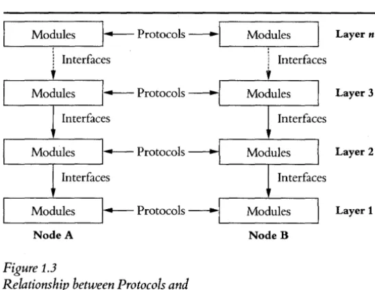
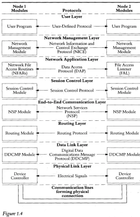
Modules with equivalent functions in the same layer, but residing in different nodes, communicate using protocols. A protocol is both a set of messages and the rules for exchanging the messages. DNA defines the message formats. and rules very specifically. Protocols provide a common code of behavior that two computer systems in a network can use to understand the role each is playing in corumunications and information exchanges. Figure 1.3 illus-trates the relationship between protocols and interfaces. Figure 1.4 illustrates protocol communication between two nodes.
11
Mo~ules I~
Protocols---I
1 Interfaces
,
~Protocols
'---__
M_o_d_u_l_es_---'~
Protocols [image:24.366.37.311.93.304.2]Node A
Figure 1.3
Relationship between Protocols and Intetfoces
Modules Layer n
1 Interfaces
,
Layer 3
Layer 2
Layer 1
NodeB
process is similar to interpreting the contents of a record on disk). Some DNA layers support more than one function and therefore include multiple protocols. An example is the Data Link layer, which supports the DDCMP, x.2S, and Ethernet protocols. The protocols that DNA defines are not exclusive; customers can substitute their own, if they choose, as long as these protocols are implemented consistently by equivalent modules throughout the network.
12· Introducing and Defining DECnet and DNA
Node 1 Node 2
Modules Protocols Modules
-User Layer
User Program
t--
User-Defined Protocol---1
User Program-Network Management Layer
Network Network Information and Network
Management Module Control Exchange Protocol (NICE) Management Module
-Network Application Layer
Network File Data Access File Access
Access Routines Protocol (D AP) Listener
(NFARs) (FAL)
-Session Control Layer
Session Control Session Control Protocol Session Control
Module Module
NSP Module - Protocol - - - . - NSP Module (NSP)
r
End-to_E~~t~::~::V~~::ion
Layer1===============
~ ~ ~ ~ ~ ~ ~ ~ ~ ~ ~'===============
Routing Layer
I
Routing Module-1IIrt---
Routing Protocol---11~
Routing ModuleData Link Layer
I ~DCMP .Module
t-
... Communications Message . Digital Data~
DDCMP Module I Protocol (DDCMP)-Physical Link Layer
[image:25.367.41.321.55.487.2]Device
1
Electrical Signals Controllerr
-I
Communication lines forming physical connectionFigure 1.4
Protocol Communications between Two Nodes
1
DeviceI
l
Controller13
. Intportance ofa Network Architecture
DNA is an open-ended architecture designed to absorb new and increasingly efficient communications technologies. It is highly adaptable to different -communications situations and supports a broad range of user applications and functions. Digital's adherence to a network architecture in the design of its communications products results in several important advantages for network customers.
Communications technology is changing continually. Future phases of DNA may model additional layers, additional modules within layers, or alternative modules for certain layers. With the wide range of available DNA facilities, organizations will be able to implement networks that are closely tailored to meet specific application needs without incurring the expense of custom-designed
networks. Currently, DNA'S Data Link layer supports three protocoIS-DDCMP, x.2S, and Ethernet. Network managers can implement the protocol best suited to meet their organization's application needs. For example, one organization's network of systems located within a limited geographical area may have a very high traffic volume among nodes. In this case, the Ethernet protocol over an Ethernet cable would be a good solution. For a network with medium traffic volume among geographically dispersed systems, the x.2S protocol might be a more cost-effective solution.
14· Introducing and Defining DECnet and DNA
Managing the different systems in a network would also be a very complicated task in the absence of a network architecture. Net-work management, error recording, and maintenance are easier when there are standard procedures for error detection, recording, isolation, recovery, and repair. An architecture provides this standardization so that network management can take place consistently across different systems. Standardization enables a network manager to manage an unattended remote system from a local node, even if the remote node is running a different operating system than that of the local node.
Yet another benefit of a network architecture is that it enables system-'independent functions to be designed specifically enough to be implemented in hardware for improved performance. For example, the DEUNA communications device implements the Ethernet data link protocol; the DMRll , DMPll, and DMvll implement the DDCMP data link protocol; and the KMSll-BD implements the x.25 frame-level protocol.
. DEC net Capabilities
DEC net enables users and applications to perform a number of high-level network functions. These include:
Task-to-task communication-Cooperating programs running under different operating systems and written in different languages can exchange data. For example, PDP-ll medical analysis systems can transfer data to a central VAX system without an operator's commands. See Chapter 5 for further details on task-to-task communication.
15
transfer of files between two nodes, the manipulation of files (opening a file, deleting data from or appending data to a file) on remote nodes, and the submission of command files for execution to a remote node in order to gain access to that node's resources
Consult Chapter 6 for additional information on remote file and record access.
Terminal-to-terminal communication-On some DEcnet
implementa-tions, a user at one terminal can use a DEcnet utility to send messages to users at other terminals in the network. Refer to Chapter 7 for further explanation.
Network terminal communication-From their terminals, users can
log on to a remote node and execute commands as if they were typing on a local terminal at that node. DEC net Phase III supports this capability if the remote node is running the same operating system as the user's local node. DEC net Phase IV supports this capability even if the operating system on the remote node is different from that on the local node.
The Phase IV capability is known as network virtual terminal. This
capability is particularly useful for program development. From their terminals, programmers can draw on the resources of any system in the network. Depending on the application they are developing, they can log on to the system best suited to their task. For example, for rapid compilation, they can submit source-code files to a high-performance VAX/VMS system. See Chapter 7 for more details on network terminal communication.
Problem isolation and Network management-Network managers can
16· Introducing and Defining DECnet and DNA
and to isolate network problems. By performing loopback tests, trace facilities, and dump analyzers (see Chapters 10 and 11 for further explanation of network management functions), network managers can monitor network nodes and keep abreast of network performance in order to identify and resolve potential difficulties before they become crises. Users can thus be assured of an error-free network.
Downline loa ding-With this DEenet capability, an entire software
system or task developed on a node with adequate peripheral and memory support can be sent to target systems for execution. For example, programmers in a manufacturing setting can develop new process monitoring and control parameters on a central system and then transfer the parameters to smaller target systems located on the factory floor.
Upline dumping-When a target system begins to fail, DEenet's
upline dumping capability automatically sends a system-image dump upline to an adjacent, larger system. For example, an RSX-11s DEe net node that has crashed can upline dump a copy of its system image to an adjacent Rsx-llM DEe net node for interpreta-tion. When the failing node is restored, it can be downline loaded to resume operation .
. Topology Alternatives
17
Greatly facilitating the configuration of wide area networks is a DEcnet feature known as routing. Routing eliminates the need for every node in a D£cnet network to be physically connected to every other node in the network. Communication hardware and line costs are greatly reduced. With the reduction in the number of physical lines, the risk of downtime due to channel failure also decreases.
Routing ensures that information from a source node is delivered to a specified destination node even if the information has to travel through several intervening nodes. In the event a line fails, DEcnet's adaptive routing feature finds an available alternative path.
DEC net Phase IV offers area routing, the method by whi~h DEC net can support very large networks (up to 63 areas with up to 1,023 nodes in each area). In an area-based network, two types of routing mechanisms operate: Levell routing is the mechanism responsible for communication within an area; Level 2 routing is responsible for communication between areas. Levell and Level 2
routing enable a node in one area to exchange data and share resources with any node in any other area of the area-based network. Chapter 2 includes a comprehensive discussion of routing in networks with and without area routing.
18· Introducing and Defining DECnet and DNA
In addition to enabling high-speed communications, Ethernet networks support a variety of communication servers (see Chapter 3 for details) that greatly reduce the cost of implementing a baseband local area network and significantly increase network performance. Communication servers are special purpose or dedi-cated nodes that perform communications functions for the other nodes in the network, thereby freeing the latter of communica-tions overhead.
DEcnet Phase IV also incorporates the X. 25 protocol for communica-tion over packet-switched data networks (PSDNS). A DEC net wide area network can, therefore, include systems linked through a PSDN. x.2S is a protocol recommended by the International Telephone and Telegraph Consultative Committee for data communications over common-carrier lines. By linking geographically dispersed systems through a PSDN, the cost of data communications can be reduced significantly. The tariffs for a packet-switched data net-work are based on the volume of data sent, rather than the distance or connect time between communicating systems. Cost savings with PSDN links can be substantial, especially when there is medium traffic volume among systems.
Through ~me physical link to a PSDN, logical links among many systems can be created. See Chapter 2 for an explanation oflogical links. Users need not worry about how the information is routed through the PSDN; the carrier that supplies the PSDN is responsible for ensuring that data is routed to the correct destination.
19
The Digital Data Communications Message Protocol (DDCMP) is the third protocol that DEcnet Phase IV incorporates at the Data Link level of DNA. Depending on what is best for their applications, network managers thus have the option of configuring networks with links that support DDCMP, x.2S, or the Ethernet protocol. Chapter 2 discusses these protocols in further detail.
In applications wherein peer relationship among nodes is not critical, organizations can save dramatically on expenses for lines and communication hardware by implementing a multipoint config-uration. In such a configuration, several nodes are dropped from a single line with a central node controlling access to that line. (See chapter 3 for additional information on multipoint lines.)
• DECnet Phases
Digital has been developing networking products based on DNA since 1975. This development effort has occurred in a series of phases. So far, there have been four DEC net phases. The products in each new phase are fully compatible with those produced in the previous phase. The sections below list the capabilities of Phase III and Phase IV DEC net nodes. (Appendix B in the Overview of Dig ita I Networking Products contains a brief history of DEcnet and discus-sions of earlier DEC net phases.)
Phase III
Functions that DEcnet Phase III systems can perform include task-to-task communication, remote file access, terminal-to-terminal communication, network terminal communication (between sys-tems running the same operating system-homogeneous syssys-tems), network management, downline loading, upline dumping, and loopback testing.
20· Introducing and Defining DECnet and DNA
The following DEC net products provide Phase III capabilities: DEcnet-20, DEcnet-l0, DEcnet/E, and DEcnet-RT.
Phase IV
Phase IV includes additional capabilities that establish Digital as a leading supplier of products for multivendor network environ-ments. In addition to being backward-compatible with Phase III, Phase IV features include:
Data link independence, to increase data link options for customers in implemehting networks. DEC net Phase IV-supported data link protocols are x.25, DDcMP,and Ethernet.
Dedicated communications server products that offload communica-tions overhead from general purpose nodes (see Chapter 3).
Increased network routing support allowing over 64,000 nodes to be configured in a network.
Enhanced network management capabilities (see Chapters 10 and 11).
Gateway support for communications with nodes using x.25 protocol over a packet-switched data network (see Chapter 8). Gateway support for communications with IBM systems in an SNA network (see Chapter 8).
Chapter 2' DECnet Concepts
Network activity involves the flow of information between nodes
across lines and circuits. Data originating at a node is routed through
the network until it reaches a specified destination node.
Nodes, lines, circuits, and routing are some major DEC net con-cepts. Knowledge of them is helpful in understanding how data flows through the network. A knowledge of routing, in particu-lar, is essential in appreciating the flexibility DEC net permits users and network managers in performing their tasks .
. Nodes
A node is a network entity-an identifiable unit capable of processing, sending, and receiving network information. A node consists of an autonomous software entity, such as an operating system, with processors and other associated hardware that implement DNA specifications. Every node in a DEC net network has a unique numeric address. This address designates the location of a node in the network, just as a street address designates the location of a building in a town.
In area-based networks, a node's address includes an area number and a node number. The area number specifies the area in which the node is located, and the node number identifies the node within the specified area. A node address in an area-based network is a 16-bit number. The first 6 bits are reserved for the area number, and the next 10 bits for the node number. This division of the 16-bit node address limits the maximum number of areas in an area-based network to 63 (26
- 1 = 63), and the maximum number of
nodes in an area to 1,023 (210
- 1 = 1,023).
22· DECnet Concept
packet en route to its destination where the packet is going. Node addresses ensure that a data packet can always be identified in terms of the node that is sending it and the node that is receiving it, regardless of the path the packet travels. (See below, under Routing, for a discussion of the routing mechanism that determines data packet paths.)
Most users find it difficult to remember numeric addresses, particularly when there are many nodes in a network. Software in the Session Control layer of DEcnet eliminates this difficulty. The system manager for each node in the network specifies names for all the nodes with which that node expects to communicate. These names are defined and stored in a database on that node and are meaningful only to the Session Control software running on that node.
Against the names in a node's database, Session Control software stores the unique numeric addresses associated with the names. A single node can be known by several names, since system managers for the different nodes in a network can assign a different node name for the same remote node. Consider a node in San Francisco. This node communicates with nodes in Boston, New York, Los Angeles, and New Mexico. Users at these other nodes access the San Francisco-based node by different names. Although a remote node can have several names, it has only one address. This address is consistent throughout the network, regardless of the name by which the node is accessed.
23
different names to refer to the node in San Francisco, the tables in each of these four nodes will have the same address against the name by which they refer to the San Francisco node.
When a user requests connection to a node and refers to it by name, the Session Control module consults the node-name map-ping table to determine the address of the destination node. It passes on this information to the End-to-End Communication Layer, which creates logical links between systems (see Chapter 4). For incoming connect requests from the End-to-End Communi-cation Layer, the Session Control module uses the node-name n1apping table to identify the node from which the request originated.
Session Control software enables users to refer to nodes by names that are meaningful to them (and which they can therefore remember easily). By means of the node-name mapping table, Session Control software finds the correct address of a node so that data arrives at its proper destination.
When system managers initially generate or configure their node into a network, they usually assign the name and address by which the node is to be known in the network. For small networks, these assignments can be hand-typed into each system. For large networks, an up-to-date master list of node addresses and names can be maintained on a particular node so that other nodes in the network can simply copy the information from the master file. (Existing nodes in the network exchange their node naInes and addresses with each newly configured node.)
24 • DECnet Concept
. Lines and Circuits
A line is a physical data path from a DEe net node to another DEenet node or from a gateway to an IBM SNA network or packet-switched data network (PSDN). A line is connected to a node by a hardware controller that drives or controls the line. Lines that use the public telephone network are often connected to a modem. Lines can be either dedicated (hard-wired) or dialup. Lines can be attached to a local area network cable or configured in point-to-point or multipoint configurations (see Chapter 3 for details on the latter two configurations).
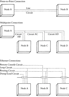
Lines form the physical connections between adjacent nodes. There is a higher level of internodal connection called circuits. Circuits are logical connections that carry information between two nodes and operate over the physical medium oflines. Each point-to-point line has one circuit associated with it, and each tributary on a multi poin t line has a circuit (see Figure 2.1). A single physical connection to an x.2S packet-switched data network (PSDN) can support many virtual circuits.
An Ethernet baseband network consists of one physical line with multiple circuits. Each circuit corresponds to a particular Ethernet protocol type. An Ethernet protocol type identifies the type of operation performed over a circuit. Figure 2.1 shows four Ethernet protocol types:
DNA routing protocol enables the operation of the DEenet routing mechanism and is required for all DEe net communications.
DNA remote console protocol provides simple internodal terminal communications used for diagnostic and maintenance procedures.
25
Point-to-Point Connection
Multipoint Connections
I'
Node A
-Ci~c~it:
- -
Ci~c~itA-C - - : - -
Cir~~itAD- - :
1 1
1 1
J - - - / - i AB :
1 1 1
/
NodeB NodeC NodeD
1/ / / I'
Ethernet Connections
Remote Console Circuit _____________ I
Lo op lrcmt __________ C· . 1_ - - - -:- - -1- - - I
Routin~ Circuit --- _ --
_1:_ ---
-:--1-: ---I :
Dump/Load Circuit _ _ 1 1 1 1 1 1 1 [image:38.362.33.307.100.481.2]~ 1 1 1 1 1 1 1
Figure 2.1 Circuits
Node A NodeB NodeC
26 • DECnet Concept
Loopback protocol enables the performance of loop tests and is required for any type of testing procedure (see Chapter 11).
There are other protocol types not shown in Figure 2.1. Refer to the bibliography in the Overview of Digit a I Networking Products for a list of Ethernet documentation that further explains protocol types.
All communication activity in the network is considered in terms of circuits. DEC net 's routing mechanism establishes a succession of circuits between a number of intervening nodes to get data from one node to another. These circuit pathways enable nodes to send data to other nodes that are not physically adjacent to them.
Transmission Modes
Information is transmitted over DEcnet lines in half-duplex or full-duplex mode. In half-full-duplex mode, the line can transmit data in either direction, but only in one direction at any given time. Data cannot be sent and received over the line simultaneously. In full-duplex mode, the line can transmit data in both directions simultaneously, thereby making it possible for a node to send and receive data at the same time. The concepts of half duplex and full duplex relate to the physical line only.
27
Once the data leaves the Routing layer, the user services and the routing mechanism assume that it has been transmitted over the specified circuit. However, if the data cannot be transmitted over the designated physical line because it is a half-duplex line already carrying data, or, in the case of an Ethernet transmission, because the channel is not free, software in the Routing layer will buffer the data until it can be transmitted. The user is not aware of when the data is actually buffered or when it is sent out directly on a free line .
. Data Link Protocols
Currently, there are three protocols residing in the DNA Data Link layer:
Digital Data Communications Message Protocol (DDCMP)-a
byte-oriented protocol
Ethernet protocol-Carrier Sense Multiple Access with Collision
Detect (CSMAI CD) with physical channel encoding and operating over a coaxial cable
X.25 Levels 2 and 3-operating over Level 1 of the CCITT x.2S recommendation, which defines a standard interface between data terminal equipment (DTE), such as a DEcnet node, and the data circuit terminating equipment (DCE) of a packet-switched data network.
This chapter will describe the DDCMP and Ethernet protocols. For additional details on the x.2S protocol, see Chapter 8.
28 • DECnet Concept
on the data link protocol that best suits their organization's application requirements. Regardless of the data link protocol they implement, network managers can be assured of error-free transmission of data, since a primary function of the Data Link layer is to ensure the integrity of transmitted data.
DDCMP Functional Description
There are three general types of data link protocols: byte-oriented, character-oriented, and bit-oriented. DDCMP is a byte-oriented proto-col. Such a protocol provides a count of the number of bytes that are sent in the data portion of each message. A character-oriented protocol uses special ASCII characters to indicate the beginning of a message and the end of a block of text, and a bit-oriented protocol uses flags to frame data sent in undefined lengths. Neither the character-oriented nor the bit-oriented protocol contains provi-sions for checking whether all the transmitted data has arrived at its destination. The advantage of a byte count in a byte-oriented protocol is that it facilitates checking on the part of the receiving node to see whether all transmitted data has been received.
DDCMP was designed in 1974 specifically for the Digital Network Architecture. DDCMP is functionally similar to HDLc-High-level Data Link Control-which was adopted in 1975 by the Interna-tional Standards Organization. (HDLC is a bit-oriented protocol, however.) Another type of data link protocol that is commonly implemented is BISYNC (binary synchronous), which is character-oriented.
29
receiving, without misinterpretation, data containing bit patterns that resemble protocol control characters). Character-oriented protocols cannot handle transparent data as efficiently as byte- or bit-oriented protocols. Other major features of DDCMP include error recording to warn of impending channel failure on degraded lines and a simplified mode for bootstrapping and testing func-tions.
DDCMP transmits data grouped into physical blocks known as data messages and provides a mechanism for exchanging error-free messages. This mechanism works in the following manner: DDCMP assigns a number to each data message, beginning with the number one (after each initialization) and incremented by one for each subsequent data message. In addition, DDCMP places a 16-bit cyclic redundancy check (cRc-16) error-detection polynomial at the end of each data message transmitted.
The receiving DDCMP module checks for errors and, if there are none, returns an acknowledgement that it has received the message. Acknowledgement is efficient since the receiving DDCMP module does not have to acknowledge each message sent. Acknowledgement of data message n implies acknowledgement of all data messages up to and including data message n. If the receiving DDCMP module detects an error, it uses time-outs and control messages to resynchronize and trigger retransmission;
30 • DECnet Concept
• Send up to 255 messages without waiting for individual acknow-ledgement of each successive message. This capability is known as
pipelining.
• Operate independently of channel bit width (serial or parallel) and transmission characteristics (asynchronous or synchronous). • Operate with a wide variety of communications hardware and
modems.
• Detect errors by means of CRc-16 message trailers. • Retransmit to correct errors.
• Achieve optimum performance with techniques such as pipelin-ing,
piggybacking
(sending an acknowledgement within a returned data message), and implying a postive acknowledgement of previous messages by negative acknowledgement of current mes-sage (see below, under DDCMP Control Messages).• Operate in half-duplex and full-duplex modes.
• Support point-to-point and multipoint communications.
· Synchronize transmission and reception on byte and message level. • Frame (construct envelopes) data messages.
• Provide a maintenance mode for diagnostic testing and bootstrap-ping functions.
• Provide data transparency.
• Notify the other end of the link when restarting or initializing. • Maintain error counters.
31
DDCMP Messages
There are three types of DDCMP messages: data, control, and maintenance. Data messages consist of user data. Control mes-sages return acknowledgements and other control information to ensure data integrity and error-free transmission. Maintenance messages consist of information for downline loading, upline dumping, link testing, or controlling a remotely located, adjacent system .
. Data Messages
DDCMP formats all messages received from the Routing layer to be sent across the physical link into a data message format (Figure
2.2). The data message format ensures proper handling and error checking of both the header information and the data being sent. (In the message format figures in this chapter, the numbers below each message field indicate the length of the field in bits.)
Data Message Format
I
SOHI
COUNTI
FLAGSI
RESPI
NUMI
ADDRI
BLKCK11 DATAI
BLKCK218 14 2 8 8 8 16 8n 16
SOH the numbered data message identifier COUNT the byte count field
FLAGS the link flags
RESP the response number
NUM the transmit number
ADDR the station address field
BLKCKl the block check on the numbered message header DATA the n-byte data field, where O<n = COUNT<214
BLKCK2 the block check on the data field
Figure 2.2
32· DECnet Concept
. Control Messages
DDCMP has five control messages that carry link control informa-tion, transmission status, and initialization notification between DDCMP modules. All the control messages operate to ensure an error-free link between sending and receiving DDCMP modules:
Acknowledge Message (ACK) acknowledges the receipt of correctly
numbered data messages that have passed the CRc-16 check. The ACK message is used when no numbered data messages are to be sent in the reverse direction. The ACK message conveys the same information as the RESP field (see Figure 2.3) in numbered data messages.
Negative Acknowledgement Message (NAK) passes error
informa-tion from the DDCMP data receiving module to the DDCMP data sending module. The NAKTYPE field (see Figure 2.3) indicates the cause of the error. The NAK message servers two purposes: it acknowledges receipt of all previously transmitted messages with a number less than the current message number received and it notifies the sender of error conditions relating to the current message.
Reply to Message Number(REP) is a message from the data sender to
the data receiver requesting a received-message status. The data sender issues a REP message when it has sent a data message, has not yet received acknowledgement of that message, and the time allocated of an acknowledgement has expired.
Start Message (STRT) establishes initial contact and
synchroniza-tion on a DDCMP link. A DDCMP module sends this message during link startup or reinitialization.
33
Figure 2.3 shows the formats of the DDCMP control messages.
Acknowledge Message (ACK) Format
I
ENQI
ACKTYPE , ACKSUBI
FLAGSI
RESP , FILLI
AD DRI
BLKCK318 8 6 2 8 8 6 16
Negative Acknowledge Message (NAK) Format
I
ENQ , NAKTYPEI
REASON' FLAGSI
RESPI
FILLI
ADDRI
BLKCK31 Reply to Message Number (REP) FormatI
ENQI
REPTYPEI
REPSUBI
FLAGSI
FILLI
NUMI
ADDRI
BLKCK31 Start Message (STRT) FormatI
ENQI
STRTTYPEI
STRTSUB , FLAGSI
FILL' FILL' ADDR , BLKCK31Start Acknowledge Message (STACK) Format
I
ENQ , STCKTYPEI
STCKSUB , FLAGS' FILL' FILL' ADDR , BLKCK31 ENQ ACKTYPE NAKTYPE REPTYPE STRTTYPE STCKTYPE ACKSUB REASON REPSUB STRTSUB STCKSUB FLAGS RESP FILL ADDR BLKCK3 Figure 2.3the control message identifier
the ACK message type with a value of1 the NAK message type with a value of2 the REP message type with a value of 3 the STRT message type with a value of 6 the STACK message type with a value of 7 the ACK subtype with a value of 0 the N AK error reason
the REP subtype with a value of 0 the STRT subtype with a value of 0 the STACK subtype with a value of 0 the link flags
the response number used to acknowledge received messages that checked out to be correct a fill byte with a value of 0
the tributary address field the control message block check
34· DECnet Concept
. Maintenance Messages
Figure 2.4 illustrates the fonnat of the maintenance message, which is used in DDCMP maintenance mode. The maintenance message is a DDCMP envelope for data controlling downline loading, upline dumping, link testing, and controlling an unat-tended computer system. The DNA protocol used in performing maintenance functions is the Maintenance Operation Protocol (MOP). MOP messages (see Chapter 10 for a description) are sent within the DnCMP maintenace message.
DDCMP Operation
The DDCMP module has three functional components: framing, link management, and message exchange.
Framing-The framing component locates the beginning and end of a message received from a transmitting nDCMP module. Fram-ing involves locatFram-ing and lockFram-ing onto, or synchronizFram-ing with, a
Maintenance Message Format
IDLEI COUNTI FLAGS I FILL I FILL I ADDRIBLKCK11DATAIBLCKCK21
8 14 2 8 8 8 16 8n 16
DLE COUNT FLAGS FILL ADDR BLCKCKl
DATA BLKCK2
Figure 2.4
the maintenance message identifier the byte count field
the link flags
a fill byte wi th a value of 0 the tributary address field
the header block check on fields D LE throughADDR
the n-byte data field, whereO<n = COUNT<214 the block check on the DATA field
35
certain bit, byte, or message and then receiving subsequent bits, bytes, or messages at th~ same rate as that at which they come in.
At the Physical Link level, modems and communications inter-faces synchronize bits. The DDCMP framing component synchro-nizes bytes by locating a certain 8-bit window in the bit stream. On asynchronous links, DDCMP uses start/ stop transmission tech-niques to synchronize bytes. On synchronous links, DDCMP searches for a SYN character. Byte synchronization is inherent in 8-bit multiple parallel links. DDCMP synchronizes messages by searching for one of the three special starting bytes (SOH, for data messages, ENQ for control messages, and DLE for maintenance messages) after achieving byte synchronization. To maintain message synchronization, DDCMP counts out fixed-length headers and, when required, counts out variable-length data based on the count field of the header.
Link Management-This component controls transmISSIOn and reception on links connected to two or more transmitting systems and/ or receiving systems in a given direction. Link management controls the direction of data flow on half-duplex links and, with the use oflink flags, controls the selection of tributary stations on multipoint links. In addition, link management uses selective addressing to control the receipt of data on multipoint links.
Message Exchange-This component transfers data correctly and in sequence over a link. Message exchange operates at the message level (after framing has been accomplished) to exchange both data and control messages.
Typical Message Exchange
acknowl-36· DECnet Concept
edgement. Such an acknowledgement is either an Acknowledge Message (ACK) or a piggybacked acknowledgement in the response (RESP) field of a data message.
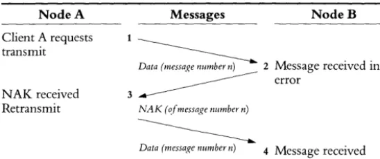
If a DDCMP module receives a message out of sequence or with an error detected by the CRC, DDCMP does not pass the data on to the Routing layer. Typically, DDCMP does not acknowledge this message. Eventually, a time-out occurs, and one of two things could happen: the data sending DDCMP module retransmits the message or the data receiving DDCMP module sends a NAK to the data sending module.
The transmission ofDDcMP data messages includes the following steps:
1. The transmitter increments the message number and puts the number, n, in the data message. This message is transmitted
within the required framing envelope. A timer is started. 2. The receiver frames and receives the message, checks the received CRC value against a computer CRC value, and compares the message number with the number it expects to receive. If the message checks out correctly, the receiver returns a positive acknowledgement (ACK) with that number, passes the message to the Routing layer, and increments the next expected number to n
+
1. If the message fails to check out, the receiver ignores the message or sends a NAK.3. The transmitter then follows one of three procedures:
37
message as well as of any previous lower-numbered outstanding messages. If all outstanding messages have been acknowledged, the timer is stopped. If one or more message remains outstanding, the timer is restarted.
If the transmitter receives nothing, the timer expires. The trans-mitter sends a REP control message to initiate error recovery. If the transmitter receives a negative acknowledgement, it retrans-mits the message and all higher-numbered messages.
The transmitter can send several data messages before requiring that the first one be acknowledged. Acknowledgement of the highest-numbered message implies acknowledgement of all lower-numbered messages. A negative acknowledgement implies postive acknowledgement of any previously transmitted, lower-numbered messages.
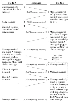
Figure 2.5 shows a message exchange involving positive acknowl-edgement and pipelining. Figure 2.6 shows error recovery from a
NAK.
Maintenance Mode
Maintenance mode uses the DDCMP framing and link management components but not the message exchange component. Sequenc-ing or acknowledgement, if required, must be handled within the data fields of the maintenance messages and is part of a higher-level protocol.
Ethernet Functional Description
Node A
Client A requests transmit of first data message
ACK received
Client A requests transmit of second data message
Message received and client A requests transmit. Acknowl-edgment of client message B is piggy-backed in RESP field of data message
Client A requests transmit
Client A requests transmit
[image:51.371.40.319.39.453.2]Message received
Figure 2.5
Messages
1~
DA TA (message number n) 2
3 ACK (oj message number n)
DATA (messaJ?e number n + 1) 5
6 DATA (message number m)
DA TA (message number n + 2) 7
~
DATA (message number n+3) 8
~
DATA (messagenumbern+4) 9
10 DATA (message number m +1)
Typical Message Exchange, with Posi-tive Acknowledgement, Piggybacking, and Pipe lining
NodeB
Message received and given to client B; client B now expects next data message to be n+l
Message received and client B requests transmit of its mes-sage. Acknowledg-ment of client A message is piggy-backed in RESP field of data message
These 3 data messages are pipclined
Message received
Message received
Node A
Client A requests transmit
[image:52.371.36.310.38.153.2]N AK received Retransmit
Figure 2.6
Messages NodeB
1
~M
Data (messaJ:e number n) 2 essage receIve ' d ' In3~
errorNAK (of messaJ:e number n)
~
Data (messaJ:e number n) 4 Message receivedDDCMP Message Exchange, showing Error Recovery
coaxial cable to perform high-level network functions (file transfer and remote resource access, for example) at the high speed supported by the Ethernet cable.
The Ethernet local area network specification is the result of an extensive collaborative effort by Digital Equipment Corporation, Intel Corporation, and Xerox Corporation. The specification includes a Physical layer and a Data Link layer.
The primary characteristics of the Physical layer are: a data rate of 10 million bits per second, a maximum station (node) separation of 2.8 kilometers, a maximum of 1,024 nodes or stations on a single Etherent LAN, a shielded coaxial-cable medium using Manchester-encoded digital baseband signaling, and support of a bus structure in the shape of a branching tree.
The characteristics of the Data Link layer include multiaccess network control, in which access to the channel is fairly distrib-uted to all nodes, and regulation of channel access through the Carrier Sense Multiple Access with Collision Detect (CSMAICD)
40 • DECnet Concept
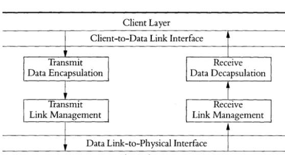
The functions of the Ethernet Data Link include data encapsulation/ decapsulation and link management:
Data Encapsulation/Decapsulation comprises framing, addressing, and error detection. Framing defines the format of message packets (the different fields of information within packets) that are broadcast over the local area network. In addition, framing constructs packets from data supplied by the nodes through the higher layers, disassembles network messages, and supplies data to the higher layer protocols of the node. Addressing handles source and destination addresses, and error detection detects physical channel transmission errors.
Link Management comprises channel allocation and channel access. Channel allocation is responsible for amount of channel use, which is determined by the definition of packet size. Channel access is controlled by the CSMA/ CD technique, part of which is carried out in each of the two layers. The Data Link layer responds to the channel or carrier sensing of the Physical layer by deferring transmission in case of traffic, transmitting in the absence of traffic, and backing off and resending in the case of a collision.
Figure 2.7 shows the two functional components of the Data Link layer, the Data Encapsulation sublayer, and the Link Management sublayer.
41
Client Layer
Client-to-Data Link Interface
Data Link-to-Physical Interface
[image:54.370.31.310.93.244.2]Physical Layer
Figure 2.7
Ethernet Data Link Layer Functions
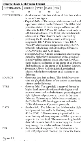
Ethernet Messages
The Ethernet Data Link layer has one type of message, the frame. The data encapsulation function of the Data Link layer comprises the construction and processing of frames. The frame format (see Figure 2.8) reflects the data encapsulation functions of framing, addressing, and error detection in the following manner:
Framing: no explicit framing information is contained in the
format since the necessary framing cues are present in the interface to the Physical layer.
Addressing: there are two address fields to identify the source and
Ethernet Data Link Frame Format
I
DESTINATIONI
SOURCEI
TYPEI
DATAI
FCSI
48 48 16 8n 32
DESTINATION
=
the destination data link address. A data link address is one of three types:• Physical Address: The unique address associated with
a particular station on the Ethernet. The 48 bit field permits a station to have a unique address over all Ethernets. In DNA Phase IV, each network node has a 16 bit node address. The 48 bit Ethernet data link address of a DNA Phase IV node is derived by prefixing the 16 bit address with a 32 bit prefix assigned to DNA Phase IV nodes. Thus, DNA Phase IV addresses are unique over a single DNA network, which may include multiple Ethernets, DDCMP links, and X.25 links.
• Multicast Address: A multi-destination address
asso-ciated by higher level convention with a group of logically related stations on an Ethernet. DNA as-signs multicast addresses to the group of all Ethernet End nodes and to the group of all Ethernet Routers.
• Broadcast Address: A distinguished, predefined
address which denotes the set of all stations on an Ethernet.
SOURCE the source data link address. This field always con-tains the physical address of the station transmitting a frame on the Ethernet.
TYPE the type field. The type field is reserved for use by higher level protocols to identify the higher level protocol associated with the frame, permitting mul-tiple higher-level protocols to coexist in the same Ethernet. Ethernet type field values are assigned to the DNA Phase IV Routing protocol and to the DNA Maintenance Operation protocols.
DATA the data field. The Ethernet data field contains higher level protocol data and is 8n bits long, where 46:5 n :51500. Full transparency is provided, in the
sense that any arbitrary sequence of8 bit bytes may appear in the data field. The minimum length of the data field ensures that all frames occupy the channel long enough for reliable collision detection.
[image:55.371.43.325.36.522.2]FCS the frame check sequence. This field contains the CRC-32 polynomial check on the rest of the frame.
Figure 2.8