SIMULATION ANALYSIS OF STATIC VAR COMPENSATOR
BASED ON THE MATLAB/SIMLINK
1 YANZHOU SUN, 2 LINLIN WEI
12School of Electrical Engineering & Automation, Henan Polytechnic University, Jiaozuo 454000 ,China
E-mail: [email protected], [email protected]
ABSTRACT
As a new kind of measure to control voltage, Static Var Compensator can rapidly, accurately and continuously adjust voltage of installation area. So it can be better sustain voltage level of installation area, improve transient stability and reduce the oscillation damping in power system. In order to study the characteristics of Static Var Compensator, this paper constructed a kind of Static Var Compensator system that includes Thyristor Switched Capacitor and Thyristor Controlled Reactor sections though Simulink toolbox of MATLAB. Then the model is used for simulation experiment. By setting the relevant parameter, this paper studied the characteristics of Static Var Compensation in power grid. The simulation results show that Static Var Compensation has a good effect in maintaining bus voltage when the power grid is in a dynamic and steady moment, and it also have a ability of the stability control. It can completely work as an important devices of reactive power compensation in power network.
Keywords: Static Var Compensation,Simulation,Thyristor Switched Capacitor, Thyristor Controlled
Reactor
1. INTRODUCTION
With the rapid development of power electronics technology and computer control technology, a variety of new type of automatic, fast reactive power compensation device have appeared [1]. Early in time, mechanical switching capacitor device is used in power grid, it was switched on group though circuit breaker or contactor. When the circuit breaker is used in the power grid to put into capacitor or filter, a great change and development have taken place. On the one hand, it may produce the stretching discharge phenomena and so on, this phenomenon will reduce action times of circuit breakers, therefore it should not to be switched frequently; On the other hand, due to the action time of mechanical circuit breaker contact is dispersion. So it is lack of synchronicity, and will inevitably produce transition process. This result may cause system shock, especially frequent switching the circuit breaker will make the system unstable [2].
But Static Var Compensator is the shunt compensation equipment of thyristor switched
type, it is on the basis of parallel capacitor and inductor of machinery investment and cut-style. Static Var Compensator is development with large-capacity thyristor instead of circuit breaker, that is a widely used in distribution system. Due to Static Var Compensator based on the method of thyristor-switched, the number of operations is almost unlimited, and switching time can be precisely controlled. The thyristor is adopted as switch to connect capacitors, reactors and other equipment to connect to the power grid, which actualizes the equipments’ speediness, no arc, no impact switching, and has superior performance. Operational difficulties and the impact of inrush current is greatly reduced when the switching time. The dynamic response time of about 0.01 to 0.02s. The same time, the Thyristor Switched Capacitor can fast-track and response to the mutation of shock loading, at any time the power factor is maintained at the optimum value. Thus realize the dynamic reactive power compensation, and to reduce the voltage fluctuations and to improve power quality [3][4].
Currently, there are many ways to applied for reactive compensation in power system as a
reactive source. The use of Static Var Compensator is one of the important initiatives. But it needs
order to better analysis of the characteristics which including voltage control capability and the response time of the Static Var Compensator used in the grid. So this paper using MATLAB / SIMUINK to carry out the simulation analysis[5].
2. MODELING AND SIMULATION
2.1 Construct the simulation model of Static
Var Compensator
In order to analyze the characteristics of the Static Var Compensator, Using SimPowerSystems Toolbox. This paper Constructed a 300-Mvar
[image:2.612.103.511.232.447.2]Static Var Compensator system that regulates voltage on a 6000-MVA, 735-kV system (frequency 50Hz) [4]. The Static Var Compensator consists of a 735kV/16-kV, 333-MVA coupling transformer, one 109-Mvar Thyristor-controlled Reactor bank and three 94-Mvar Thyristor-switched Capacitor banks (TSC1, TSC2, TSC3) connected on the secondary side of the transformer (frequency 50Hz) [6][7]. The simulation model of Static Var Compensator system is shown in figure 1.
Figure 1: Simulation model of Static Var Compensator
2.2.2 Simulation parameters
(1)Setting up parameters [8][9]: Simulation starting time: 0 seconds; Simulation ending time: 1 seconds;
Differential equation solver : a variable step size algorithm, ode23s ( stiff / Mod Rosen brock ).
Maximum step size: automatic mode; Smallest step size: automatic mode; Initial step size: automatic mode;
Relative tolerance: 1.0 10× -3; Absolute tolerance: automatic mode.
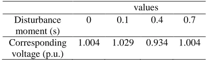
(2)Setting disturbance parameter of Static Var Compensator system:
This disturbance parameters of Static Var Compensator system in Tab.1.
And the control mode of Static Var Compensator is the "voltage regulator", the reference voltage is set as .
Table 1: Disturbance parameters of Static Var Compensator system
values Disturbance
moment (s)
0 0.1 0.4 0.7
Corresponding voltage (p.u.)
1.004 1.029 0.934 1.004
3. SIMULATION AND RESULT ANALYSIS
Simulation analysis of the Static Var Compensator in the normal working. Run the simulation and observe waveforms on the Static Var Compensator scope block, the simulation waveforms for the Static Var Compensator is shown in Fig.2.
[image:2.612.312.525.510.572.2]resulting in a 1.0 p.u. voltage at Static Var Compensator terminals when the static Var Compensator is out of service. As the Static Var Compensator is in a suspension state, the port current is initially floating (zero current). In this operating point, the Thyristor Switched Capacitor 1 (TSC1) is conducting (Qc= −94Mvar), and the Thyristor Controlled Reactor bank is at full
conduction (alpha=96 degrees). And the voltage droop of the regulator is 0.01 p.u./100VA (0.03p.u./300MVA). Therefore when the Static Var Compensator operating point changes from fully capacitive (+300 Mvar) to fully inductive (-100 Mvar), the Static Var Compensator voltage varies between 1-0.03=0.97 p.u. and 1+0.01=1.01 p.u.. -2 -1 0 1 2 (a) V a/ p. u. -5 0 5 (b) la/ p. u.
0 0.1 0.2 0.3 0.4 0.5 0.6 0.7 0.8 0.9 1 -200 0 200 400 t/s Q / M v ar (c) 0.9 0.95 1 1.05 1.1 (d) V m eas V r ef / p. u. 50 100 150 200 (e) al pha T C R / deg
0 0.1 0.2 0.3 0.4 0.5 0.6 0.7 0.8 0.9 1 -1 0 1 2 3 4 (f) num ber of T S C s t/s Vmeas Vref
(a) Primary side voltage of transformer;(b) Primary side current of transformer; (c) Primary side reactive of transformer;(d) Average voltage and reference voltage;
(e) Triggering angle of Thyristor-controlled Reactor;(f)Numbers of Thyristor-controlled Reactor conduction Figure2: Simulation waveform of Static Var Compensator
At t=0.4s, the source voltage is suddenly lowered to 0.934 pu. The Static Var Compensator reacts by generating 256 Mvar of reactive power, thus increasing the voltage to 0.974 pu. At this point, the three Thyristor-switched Capacitors are in service and the Thyristor-controlled Reactor absorbs approximately 40% of its nominal reactive power (alpha =120 degrees). Observe on the last trace of the scope how the Thyristor-switched Capacitors are sequentially switched on and off. Each time a Thyristor-switched Capacitor is switched on the Thyristor-controlled Reactor alpha angle changes suddenly from 180 degrees (no conduction) to 90 degrees (full conduction), as shown in Figure 3(e) and Figure 3(f). Because the Thyristor-switched Capacitors is put into working, this stage of the voltage and current are also not synchronized, the current is almost ahead of the voltage by 90 degrees.
It can be seen from Figure3 that the switching sequence of the Thyristor-switched Capacitors. Every time a Thyristor-switched Capacitors is put into working, the Thyristor-controlled Reactor alpha angle suddenly changed from 100 degrees (conduction) to 180 degrees (non-conduction). However, when the Thyristor-switched Capacitor are shut, the Thyristor-controlled Reactor alpha angle suddenly changed from 180 degrees (non-conduction) to 100 degrees ((non-conduction).
Finally, at t=0.7s the source voltage is increased to 1.0 p.u. and the Static Var Compensator reactive power is reduced to zero. Simulation analysis of the Static Var Compensator in faulting working. Each time a Thyristor-switched Capacitor (TSC) is switched off a voltage that remains trapped across the TSC capacitors. If you look at the 'TSC1 Misfiring' scope, inside the "Signals and Scope" subsystem, you can observe the TSC1 voltage (first trace) and the TSC1
current (second trace) for branch AB. The voltage
the pulses sent to this thyristor are shown on the 4th trace. Notice that the positive thyristor is fired at maximum negative TSC voltage, when the valve voltage is minimum. If by mistake the firing pulse is not sent at the right time, very large overcurrents can be observed in the TSC valves.
In order to analyze this case, it should be adjust the parameters of control system. Look inside the Static Var Compensator Controller
block how a misfiring can be simulated on Thyristor-switched Capacitor1. A Timer block and a OR block are used to add pulses to the normal pulses coming from the Firing Unit. Open the Timer block menu and remove the 100 multiplication factor. The timer is now programmed to send a misfiring pulse lasting one sample time at time t=0.121s.
-5 0 5 10x 10
4
(a)
V
ab-s
ec
/k
V
V
ab-C
-T
S
C
1/
k
V
-10 -5 0 5x 10
4
(b)
V
th-T
S
C
1/
k
V
-1 0 1 2x 10
4
(c)
lab-T
S
C
1/
k
A
0.09 0.1 0.11 0.12 0.13 0.14 0.15 -1
0 1 2
(d)
P
ul
s
e-th+
A
B
t/s
[image:4.612.104.503.209.420.2]Vab-Sec Vab-C-TSC
Figure 3: Voltage and current waveform of Thyristor-switched Capacitor Misfiring
Restart simulation. Observe the voltage and current changes of Thyristor-switched Capacitor1 is shown in Fig.3. From top to bottom of these waveforms is ab phase voltage of transformer secondary side winding on a capacitor in a transformer secondary winding side of the ab phase line voltage, voltage of Thyristor-switched Capacitor1’s capacitor, thyristor voltage of Thyristor-switched Capacitor1, current of of Thyristor-switched Capacitor1’s capacitor and thyristor’s trigger pulse of Thyristor-switched Capacitor1.
Observe that the misfiring pulse is sent when the valve voltage is maximum positive immediately after the TSC has blocked. Thisthyristor misfiring produces a large thyristor overcurrent (18 kA or 6.5 times the nominal peak current). Also, immediately after the thyristor has blocked, the thyristor voltage reaches 85 kV (3.8 times the nominal peak voltage). In order to prevent such overcurrents and overvoltages, thyristor valves are normally protected by metal oxide arresters.
4. SUMMARY
ACKNOWLEDGEMENT
This research was partially supported by the National Natural Science Foundation of China U1204506 (Research on dielectric barrier discharge with micro configuration).
REFRENCES:
[1] Gu Yonggang, Xiao Guochun, Wang Zhaoan. “Progress of thyristor switched capacitor’s technology”, High Voltage Apparatus, Vol. 39, No. 2, 2003, pp. 49-52.
[2] Li Tao. “Application of 10kV thyristor switched
capacitors in the substation”, Electric Age, No.
7, 2008, pp. 96-98.
[3] Zhao Xinwei, et al. “Practical techniques of
reactive power compensation in low-voltage system”, Publishing House of Electronics
Industry, Beijing , 2011.
[4] Kamari, N.A.M., Musirin, I., Hamid, Z.A., Rahim, M.N.A.. “Optimal design of SVC-PI
controller for damping improvement using new computational intelligence approach”, Journal
of Theoretical and Applied Information
Technology, Vol 42, No 2, 2012, pp. 271-280.
[5] Chen Guiming, Zhang Mingzhao. “Application
of MATLAB Modeling and Simulation”, Science Press, Beijing , 2001.
[6] Zhang Li, Li Qingmin, Wang Wei, Siew Wah Hoon. “Electromagnetic interference analysis
in HV substation due to a static var
compensator device”, IEEE Transactions on Power Delivery, Vol. 27, No.1, 2012,
pp.147-155.
[7] Huang Shao-Ping, Li Yong-Jian, Jin Guo-Bin,
Li Ling. “Simulation study for steady-state and
dynamic performance of the static var compensator”, 2009 International Conference
on Energy and Environment Technology, ICEET 2009, Vol. 2, 2009, pp. 287-290, 2009
International Conference on Energy and
Environment Technology, ICEET 2009.
[8] Wang Jing, Weng Guoqing, Zhang Youbing. “Simulation and application of MATLAB/SIMULINK in power system”, Xi'an University of Electronic Science and Technology Publishing House, Xian , 2008. [9] Li Hua. “Simulation of power systems using