ISSN: 1992-8645 www.jatit.org E-ISSN: 1817-3195
RESEARCH ON UNDERGROUND TUNNEL EMERGENCY
ROUTE GENERATING ALGORITHM
1MI HONGYAN, 2XIAOLING
1
Assoc. Prof., Faculty of Land Resource Engineering, Kunming University of Science and Technology 2Lecture, Faculty of Foreign Languages and Cultures, Kunming University of Science and Technology E-mail: [email protected] , [email protected]
ABSTRACT
This paper researches the emergency route generating algorithm based on the mine data. This algorithm considers the factors such as the slope and the like and realizes the rejection of adverse factors such as the shaft by setting corresponding threshold value, so as to ensure that the finally generated route has more obvious effectiveness.
Keywords: Digital Mine(DM), The Real-Time Solution Of Emergency Route(TRTSOER) , Dijkstra
Algorithm(DA)
1. INTRODUCTION
There are a lot of applications for digital mine, and wherein the real-time solution of emergency route is one of the significant applications [1-6]. Based on the mine data management, when emergency occurs, the positioning of the dangerous point and the real-time solution of the emergency route towards the exit or the hedge point will assist the management effectively to realize the decision-making.
Based on the spatial database, a kind of emergency route real-time generating algorithm for the underground tunnel has been researched. Several practical factors are introduced as the control factor in this algorithm, such as the slope factor which can filter the shaft out automatically, it is tested, and the final effect is remarkable.
In this thesis there are seven sections. Section 1 presents the introduction of the thesis. In section 2, we propose the basic theory of graph theory. Section 3 presents the underground tunnel modeling technology. In section 4, we will deal with basic data structure. In section 5, we will discuss the positioning of sudden point and data. Section 6 presents solution of shortest route by dijkstra algorithm. In the last section, we will draw a conclusion of the whole paper.
2. THE BASIC THEORY OF GRAPH
THEORY
The solution of emergency route always involves the problem of traversing the underground tunnel. In the research of this thesis, the tunnel is
abstracted and is finally simplified as the connection relation between point and line. Such topological relation belongs to the scope of graph theory. The solution of the route based on this data structure involves the problem of graph traversal actually. For the graph traversal, there are breadth-first traversal and depth-breadth-first traversal. It will introduce these two forms of traversal below.
2.1Breadth-Firsttraversal Algorithm
Breadth-first traversal is traversing the graph gradually according to level. At first, a point is selected as the starting point of traversal, and every point which has the connection relation with this point is accessed. It will propel downwards to continue to access the points which have the direct connection relation with the sublayer after accessing the points with the direct connection relation, and it will cycle until the end. You should note that, the accessed points should be marked with “accessed” during the process of traversal, so as to avoid the infinite loop. The result of the breadth-first traversal of the undirected graph G in Figure 1 is Vl → V2 → V3 → V4 → V5 → V6 → V7 → V8.
2.2 Depth-First Traversal Algorithm
depth-first traversal algorithm. The result of the depth-first traversal of the undirected graph G in Figure 1 is Vl→V2→V4→V8→V5→V3→ V6 → V7.
Figure 1: Undirected Graph G
3. THE UNDERGROUND TUNNEL
MODELING TECHNOLOGY
The tunnel network is composed by tunnels. The tunnel is abstracted and can be described by center line. The modeling can be realized by way of combining the center line with the cross section. Corresponding to GIS theory, the center line is abstracted as a segmental arc, and the nodes forming the center line are considered as the nodes forming the segmental arc. When modeling towards the underground tunnel, the coordinate of the nodes forming the center line of the tunnel is given data and is supplemented with the width of the tunnel at the same time.
The main procedure of the tunnel constructing algorithm in cross section along the center line of the tunnel is that:
1) All nodes are traversed along the direction of the center line of the tunnel, so as to get the vector in the direction perpendicular to the direction of the center line and the coordinate of the points at the position of the half width of the tunnel;
2) The points of all side edge points corresponding to the tops of the side edges of the tunnel are calculated according to the presupposed height of the tunnel;
3) The top points are encrypted according to the controllable top arc of the tunnel;
4) All fixed points are connected orderly, so as to build the three-dimensional grid model.
Figure 2: Solution Schematic Diagram of Tunnel Cross Section
Figure 2 is the solution schematic diagram of a cross section, wherein, the point A is a node at the center line of the tunnel, and the point 1 and the point 2 are the nodes which are gotten by solving according to the research of the tunnel width and the direction of side edge perpendicular to the center line of the tunnel. The point 3 and the point 4 are the top points of side edge which are gotten by solving according to the width and height of the tunnel. The top point 5 is the specific top point which is gotten by solving with the top arc. Actually, the feature points of the underground tunnel have been solved by solving the top points 1, 2, 3, 4 and 5. From the angle of visible effect, the cross section of the tunnel should be encrypted further to get the model with better visual effect, so the top points 6, 7, 8 and 9 have been gotten by encryption computation.
[image:2.612.93.298.93.297.2]Figure 3 is the modeling effect for a section of underground tunnel, and Figure 4 is the render effect of this tunnel with local illumination.
Figure 3: Grid Model for a Section of Tunnel
Figure 4: Render Effect of the Tunnel with Local Illumination
[image:2.612.311.528.477.714.2]4. BASIC DATA STRUCTURE
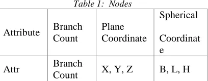
Table 1: Nodes
Attribute Branch Count
Plane Coordinate
Spherical
Coordinat e
Attr Branch
Count X, Y, Z B, L, H The node structure is the basic data structure, in addition to the storage of the information of three-V1
1
V4
V5
V3
V6 V7
[image:2.612.317.521.630.710.2]ISSN: 1992-8645 www.jatit.org E-ISSN: 1817-3195
[image:3.612.107.284.260.331.2]dimensional plane coordinate (X, Y, Z), and it also includes the longitude and latitude (B, L, H), the attribute (Attr) and the Branch Count (BranchCount). In practice, the specifically adopted coordinate system may be different because of the difference of application environment. It uses the plane coordinate sometimes and uses the longitude-latitude coordinate at other times. The attribute field is mainly used for reserving the compatibility towards the point features (for example, whether this point is a fan or a special object and so on). The branch count is not only used for distinguishing the key nodes from the nodes with generic features but also used in the step of data pretreatment.
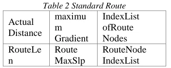
Table 2 Standard Route
Actual Distance
maximu m Gradient
IndexList ofRoute Nodes RouteLe
n
Route MaxSlp
RouteNode IndexList
The standard route structure includes the actual distance (RouteLen) of the route, the maximum value of the side slope of the route (RouteMaxSlp) and the point number index list of the nodes of this route (RouteNodeIndexList). Using the index instead of the actual node information can reduce the waste of computer memory resource on the one hand and can avoid the problem of edge crack caused by the operation of calculation concerning the key node data. As a result, if the volume of nodes is too large, and it does not store after optimization, the time delay caused by path-finding algorithm will be hard to realize the practical value.
There are 22401 nodes of the mine tunnel which is the research object of this thesis, but the key nodes are 3368 only. In this way, the data volume to be processed directly by the path-finding algorithm is 1/7 of the total volume approximately, which reduces the load of CPU greatly.
Table 3: Structure of Mine Tunnel Node
Container
Standard Route Table
Exit Coordinate Table
m_NodeTbl m_RouteTbl m_ExitTbl
The final tunnel model includes the node container which contains all nodes forming the tunnel and the standard route table which includes the sequence from all terminal points/pivot points to terminal points/pivot points. Because the standard route does not branch and is a single route, only the starting pint and the end point of the standard route are considered in the path-finding algorithm, which rejects a lot of node data further,
so as to accelerate the path-finding algorithm. The exit coordinate table includes all effective entrances and exits of the mine and may also include the emergency hedge points and the like. The final path-finding algorithm will solve the routes to every point in the exit coordinate table according to the position of the sudden point, for reference and comparison.
5. THE POSITIONING OF SUDDEN POINT
AND DATA REJECTION
5.1. The Positioning of Sudden Point
Let point P be the sudden point, traverse the edge data and select the edges in succession as the current edge for the following judgment with the point P. The relationship between the point Pand the edge AB is judged as follows (as shown in
Figure 5.4): getting point
A
as the origin andcalculating the vector
AP
=
(
x
−
x y
a,
−
y h h
a,
−
a)
and the vector
AB
=
(
x
b−
x y
a,
b−
y h
a,
b−
h
a)
, ifthe dot product
AP AB
⋅
<
0
, the pointP
isbeyond the range of the edge
AB
; getting pointB
as the origin and calculating the vector(
b,
b,
b)
BP
=
x
−
x y
−
y h h
−
and the vector
(
a b,
a b,
a b)
BA
=
x
−
x y
−
y h
−
h
. Similarly, if the
dot product BP BA⋅ <0, the point
P
is beyond therange of the edge
AB
; if the pointP
passes the dot product test of two terminal points (point A andpoint B), which means AP AB⋅ ≥0 and
0 BP BA⋅ ≥
, it proves that this point is located inside the range of current edge. Subsequently, for the distance test, the distance threshold value is set
as
iMaxDistRng
=
3.0
m
, so as to get(
)
(
)
cos
θ
= BP BA ⋅ BP BA⋅ . If the spatialdistance between the point
P
to the edge2
1 cos
PL
=
BP
⋅
−
θ
<
iMaxDistRng
,It will determine the topological position of the point P in the tunnel.
A(xa,ya,ha)
B(xb,yb,hb) P(x,y,h)
L
Figure 5: Positioning of Sudden Point
[image:4.612.98.276.73.166.2]5.2. The Rejection Of Data Set Under Constraint Condition
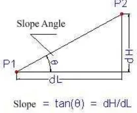
Figure 6 : Schematic Diagram of Gradient Calculation
It sets the slope factor
θ
(Figure 6) to control the route to be generated finally. If the maximum slope of a standard route is more than given slope factor, when the adjacency table is set up, this standard route will be rejected from the table and will not take part in the solution of final route. In the research of this thesis, the default slope factor is 40 degrees, which means that the slope of finally generated emergency route will not be more than 40 degrees. Under such constraint, the shaft and the steep inclined shaft are rejected by implicit expression successfully.At the same time, corresponding wind speed attenuation model can be set up under the circumstance with sufficient data, and it can also consider various conditions such as the rail carrier vehicle and so on to control the data set taking part in the solution of finial route, so as to control the quality of the finally generated route. Therefore, the research of this thesis has reserved corresponding port.
During the generation of emergency route of mine, it requires introducing the slope, the tunnel closed state information and the like as the constraint conditions, and only the route generated under such constraint conditions is available.
6. SOLUTION OF SHORTEST ROUTE BY
DIJKSTRA ALGORITHM
Dijkstra algorithm is a typical solution algorithm for shortest route and is used for calculating the shortest route from one node to all other nodes in
the adjacency graph. It is mainly characterized in that it expands outwards layer by layer by the width traversal algorithm with the starting point as the center until the end. Usually, there are two forms of general formulation of Dijkstra including one form of permanent and temporary marks and the other form of OPEN and CLOSE tables, and here we adopt the form of OPEN and CLOSE tables.
Main process:
Creating two chain tables: OPEN table and Close table. All generated nodes which have not been accessed are stored in the OPEN table, and the accessed nodes are recorded in the CLOSE table.
1). The point which is closest to the starting point in the graph but has not been checked is accessed, and this point is positioned in the OPEN table for checking.
2). The point which is closest to the starting point in the OPEN table is found out, all child nodes of this point are found out at the same time, and then this point is positioned in the CLOSE table.
3). All child nodes of this point are traversed. The distance value between these child nodes and the starting point are obtained, and the child nodes are positioned in the CLOSE table.
4). Repeat steps 2 and 3, until the OPEN table becomes empty or the target point is found.
For the mine emergency route generating algorithm, it requires introducing the state information such as the slope, the tunnel closure and the like as the constraint conditions, and only the route generated under such constraint conditions is available. The route generating algorithm finally realized by this project takes these factors into full consideration.
7. CONCLUSION
[image:4.612.123.258.202.314.2]ISSN: 1992-8645 www.jatit.org E-ISSN: 1817-3195
comprehensiveness of the data included in the mine data base.
REFERENCES
[1] Si Lianfa, Wang Wenjing. Realization of Optimal Algorithm for Fast Dijkstra Latest Path [J]. Bulletin of Surveying and Mapping. 2005, 8:15-18.
[2] DIJKSTRA E W. A Note on Two Problems in Connection With Graphs [J]. Number. Math. 1959(01):269-271
[3] Global Optimal Path Searching of AGV [J]. Journal of Sichuan University (Natural Science Edition). 2008, 45(5):1129-1136.
[4] HAN Gang, JIANG Jie, CHEN Jun, CAO Yuanda. An Arc Based Dijkstra Algorithm for Road Turning Penalty in Vehicle Navigation System [J]. Acta Geodaetica et Cartographica Sinica. 2002, 31(4): 366-368.
[5] Li Li, TANG NingJiu, LIN Tao. A* Algorithm Based on Map Segmentation and Vector Information Described Map [J]. Journal of Sichuan University (Natural Science Edition). 2010, 47(4):729-734.
[6] YUAN Jiangbo, MU Panliang, SHI Le. Efficient Path-Finding Algorithm of Virtual Vehicle in Large-Scale Scene [J]. Computer Engineering and Design. 2008, 29(10):2622-2625.
[7] Gengxiaoyun,A Preliminary Study on the Application of Multimedia Technology in College English Teaching,The Social Science Edition of Journal of Kunming University of Science and Technology, 2006, 12